Fab Academy Project: 12V DC Pump
Introduction
The ninth week’s task was to develop a project relevant to our engineering field that comprehends all the learnt knowledge and skills from the previous weeks. The project me and my colleagues decided to execute is the (DC 12V) pump. 12V water pump also named 12 volt dc water pump refers to an electric water pump motor that powered by a 12 volt direct current power supply. the water inlet of the water pump can be inserted into a pipe or used directly in the water. These types of the pumps are only suitable for experiments, not recommended for continuous use. The advantages of using this type of pump: More economical due to the use of the alternative sources of power such as solar power. Also, portable and smaller in sizes. Simpler operation and speed control methods. Less operational and maintenance costs.
The project can be separated into three parts. Firstly, the design of structure and supports. Secondly, the electronics including the programing and connections. Finally, assembling the parts and electronics to yield the finalized.
I mainly worked on the electronics, the electronics connections and some brief coding and programing of the instrument.
Design
360 Fusion was used in order to design the case of the pump and it was cutting used CO2 laser
More details about CO2 laser fabrication can be found in our main website here.
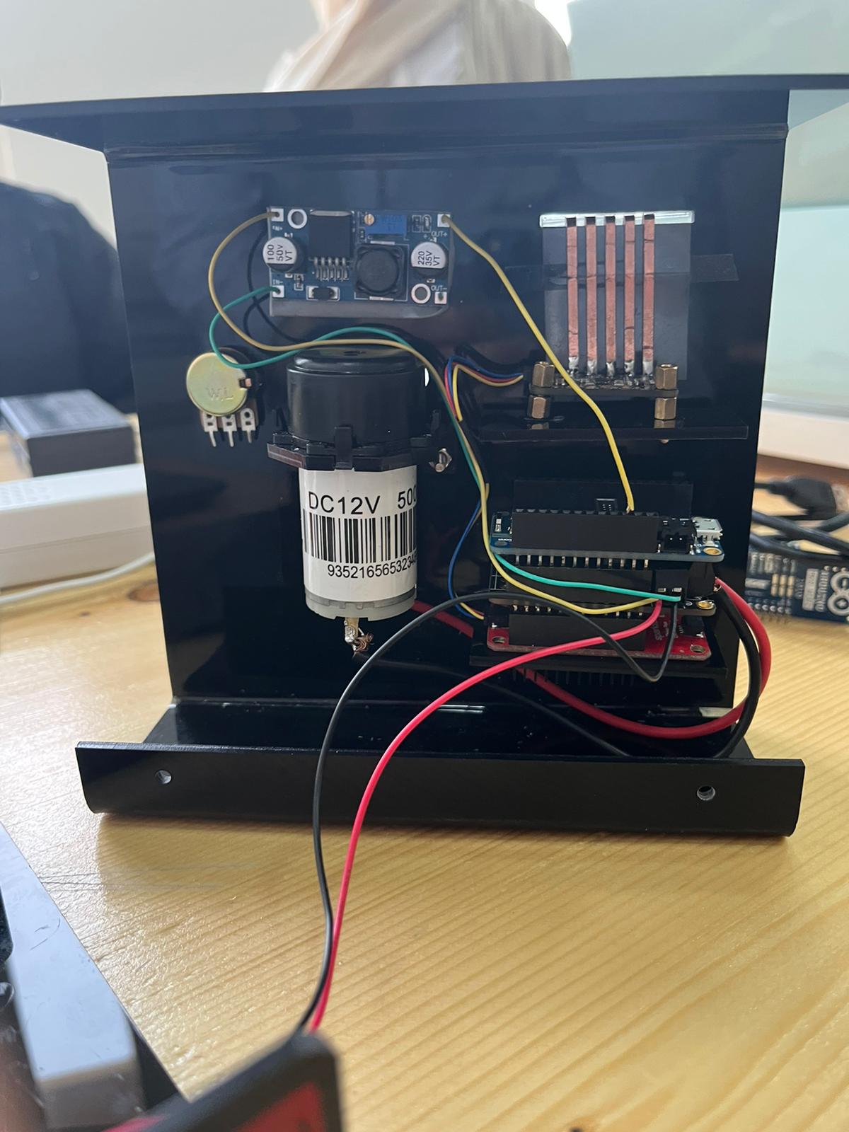
Electronics
The electronics used in DC pump are the power supply, the Arduino microcontroller, the driver, (DC motor), I2c capacitive touch sensor .
DC Motor and Driver
A DC motor or direct current motor is an electrical machine that transforms electrical energy into mechanical energy by creating a magnetic field that is powered by direct current. When a DC motor is powered, a magnetic field is created in its stator. The field attracts and repels magnets on the rotor; this causes the rotor to rotate. The motor rotates based on the specified speed for the motor. Actually, we don’t call it speed because it doesn’t correlate to a particular number of revolutions per minute (RPM). RPM depends on the motor and the voltage which is unknown. So, to a motor you can set the throttle attribute. The throttle range will be from -1 to 1 however, the motor will rotate in the reserve direction at the negative values. Therefore, the range that were used from 0 to 1. We observed that the motor starts rotating at 0.5 throttle. As it shown below when the setup was at 0.4 throttle the motor does not work probably.
the DC motor looks like:
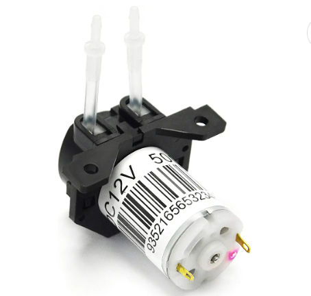
Adafruit Stepper + DC Motor FeatherWing was utilizied as a driver for th DC pump which will supply a power of 12 V for the pump itself by converting the power from power adapter into the dc pump.
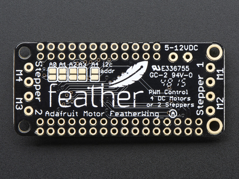
Motor FeatherWing Specs: - 4 full H-Bridges: the TB6612 chipset provides 1.2A per bridge with thermal shutdown protection, internal kickback protection diodes. Can run motors on 4.5VDC to 13.5VDC. - Up to 4 bi-directional DC motors with individual 12-bit speed selection (so, about 0.02% resolution) - Up to 2 stepper motors (unipolar or bipolar) with single coil, double coil, interleaved or micro-stepping. - Motors automatically disabled on power-up - Big 3.5mm terminal block connectors to easily hook up wires (18-26AWG) and power - Polarity protected 2-pin terminal block and jumper to connect external power, for separate logic/motor supplies - Completely stackable design: 5 address-select jumper pads means up to 32 stackable wings: that’s 64 steppers or 128 DC motors! What on earth could you do with that many steppers? I have no idea but if you come up with something send us a photo because that would be a pretty glorious project.
Power Supply
The power supply converts the electrical power attained from the source into the specified voltage for the application. It is the main source of power for the electronic parts. The connections of the wires were connected into Motor FeatherWing chip.
Microcontroller and Circuit_python
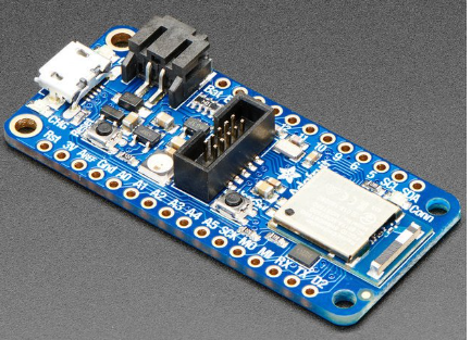
The Arduino microcontroller was utilized as the heart of the electronics of the DC pump by controlling the instrument, where it contains the code program that is used in order to control the DC pump. In addition, Circuit Python was used to write the code . Circuit-Python is a programming language designed to simplify experimenting and learning to code on low-cost microcontroller boards and learning to code on low-cost microcontroller . Circuit-Python is easy to use because all you need is that microcontroller board, a USB cable, and a computer with a USB connection. But that’s only for beginning in order to program code then it will be saved directly in the board even without PC connection. Mu-Editor was downloaded to write the code from this link
microcontroller that was used is Adafruit nRF52840 Feather and it looks like:
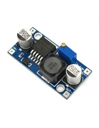
convertor
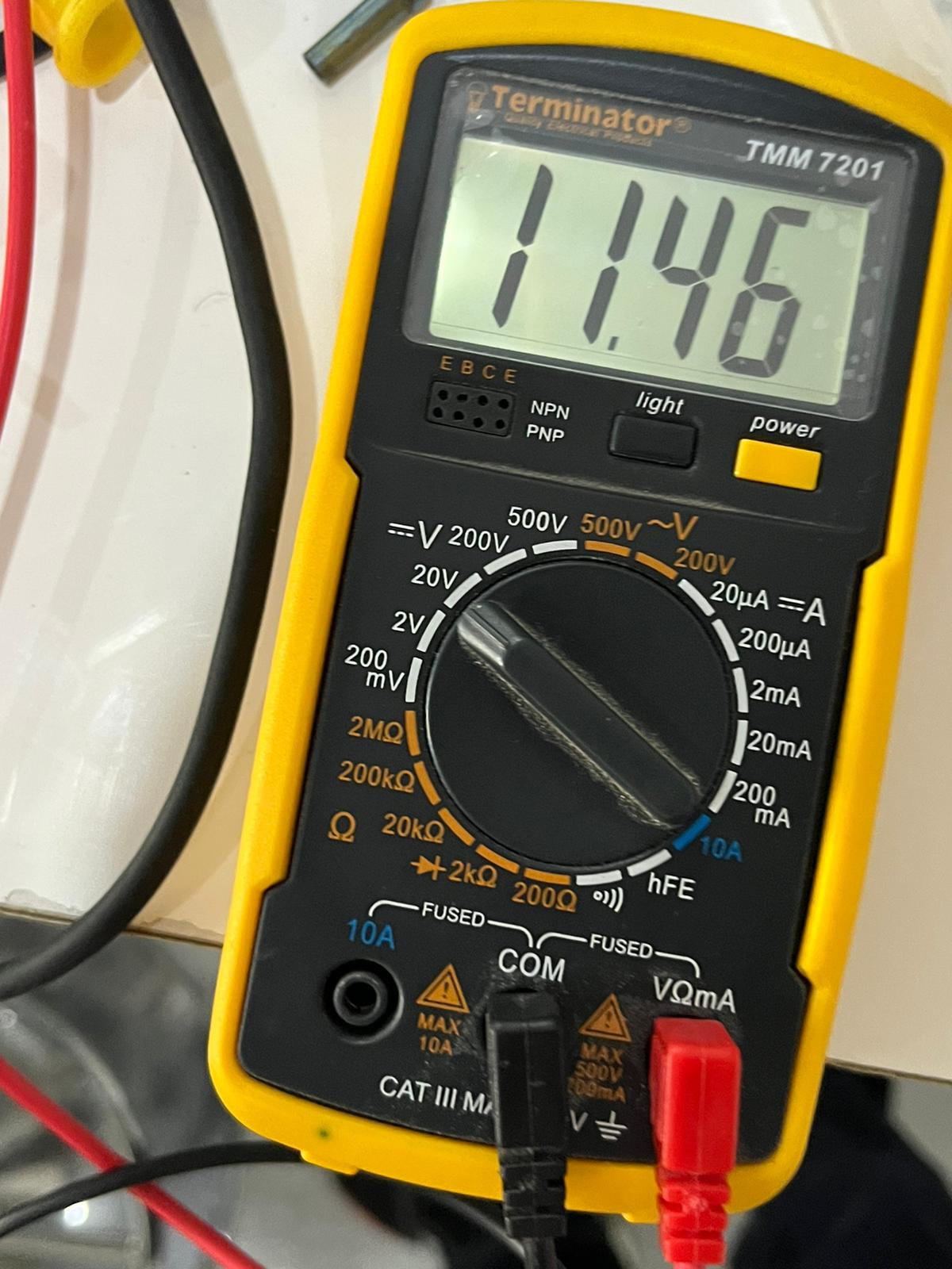
Since we will disconnect the PC from the micro and therefore a power supply source is required to give 5v for microcontroller, so we used the convertor chip called (LM2596 DC-DC Buck Converter Step Down Module). Which will take the power from the Motor FeatherWing chip and convert it into 5v then will connect into microcontroller board. first we measured the voltage using the multimeter device in order to make sure the power gives 5V and if not we have to adjust it until we will get 5 v.
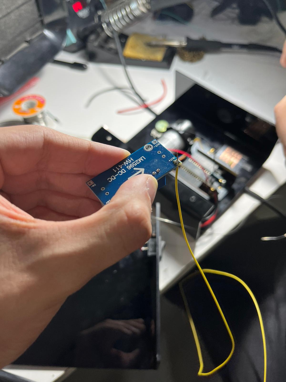
the multimeter:
this is the way of how we adjusted in order to get 5v:
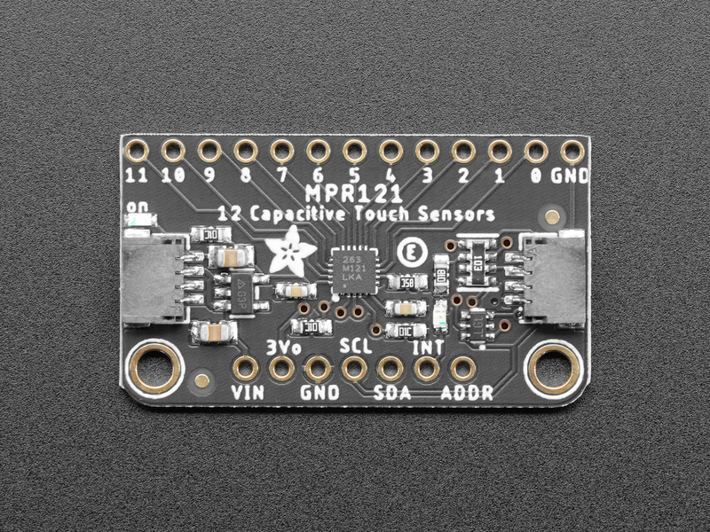
Adafruit MPR121 12-Key Capacitive Touch Sensor
The MPR121 has support for only I2C, which can be implemented with nearly any microcontroller. You can select one of 4 addresses with the ADDR pin, for a total of 48 capacitive touch pads on one I2C 2-wire bus. Using this chip is a lot easier than doing the capacitive sensing with analog inputs: it handles all the filtering for you and can be configured for more/less sensitivity. Know what we did is that we were used only 5 pins and each pin will indicate different flow rate ( i.e different throttle and time) that will be discussed with the code and calibration section
The all boards will be connected to each other in a parallel way, and for the touch capacitive sensor there will be a shield called SparkFun Qwiic Shield where it will connect the i2c chip with others as shown in following:

code and calibration
The code is simple, and It’s easy to use and link the MPR121 sensor CircuitPython and the Adafruit CircuitPython MPR121 module with the Adafruit Stepper + DC Motor FeatherWing. but we have to import some libraries that are used to control DC motor with the Adafruit Stepper + DC Motor FeatherWing. Such as, MotorKit
The code that was used is shown bellow:
# SPDX-FileCopyrightText: 2017 Limor Fried for Adafruit Industries
#
# SPDX-License-Identifier: MIT

"""CircuitPython I2C Device Address Scan"""
# If you run this and it seems to hang, try manually unlocking
# your I2C bus from the REPL with

# from adafruit_ble import BLERadio
# from adafruit_ble.advertising.standard import ProvideServicesAdvertisement
# from adafruit_ble.services.nordic import UARTService
import time
import board
import busio
# ble = BLERadio()
# uart = UARTService()
# advertisement = ProvideServicesAdvertisement(uart)

# ble.start_advertising(advertisement)
# while True:
#    Normally other work would be done here after connecting.
#   pass

# To use default I2C bus (most boards)
i2c = board.I2C()
import adafruit_mpr121
from adafruit_motorkit import MotorKit
# To create I2C bus on specific pins
#i2c = busio.I2C(board.SCL, board.SDA)  # QT Py RP2040 STEMMA connector

mpr121 = adafruit_mpr121.MPR121(i2c, 0x5A)
kit = MotorKit()
touched = mpr121.touched_pins
# while not i2c.try_lock():
#    pass

# try:
while True:
    # print(i2c.scan())
    if mpr121[0].value:
        print("Pin 0   10 Second")
        kit.motor1.throttle = 1
        time.sleep(10)
        kit.motor1.throttle = 0
    time.sleep(0.2)

    if mpr121[2].value:
        print("Pin 2   0.5 Second")
        kit.motor1.throttle = 1
        time.sleep(2
        kit.motor1.throttle = 0

    time.sleep(0.2)

    if mpr121[4].value:
        print("Pin 4    1.0 Second")
        kit.motor1.throttle = 0.7
        time.sleep(10)
        kit.motor1.throttle = 0
    time.sleep(0.2)

    if mpr121[6].value:
        print("Pin 6    10 Second")
        kit.motor1.throttle = 0.7
        time.sleep(2)
        kit.motor1.throttle = 0
    time.sleep(0.2)

    if mpr121[8].value:
    time.sleep(0.2)

        print("Pin 8  10.0 Second")
        kit.motor1.throttle = 0.5
        time.sleep(10)
        kit.motor1.throttle = 0
    time.sleep(0.2)
# finally:  # unlock the i2c bus when ctrl-c'ing out of the loop
#    i2c.unlock()
from the code it can shown that for each pin there are specified throttle and time where the pump will rotate and take the water at these specifications We measured the output of the fluid using syringe and then we divided the volume of the fluid by the time in order to get the flow rate then we know at these specifications what is the flow rate. So we went back for the code and adjusted it based on the flowrate for example I know that when I have throttle equal to 1 and time is 10s we will get 1 ml/s so I defined these specification at pin 0 so when will touch the sensor at pin zero will know that will get 1 ml/s and so on.
these are some videos of testing the pump:
- 10 seconds and throttle 1 setting
- 10 seconds and throttle 0.5 setting
- 10 seconds and throttle 0.4 setting