7. Input & Output device
This week I worked on the input and the output devises. Where it is use to control or present a specifc motion or action. The Input is the action that you want the sensor or the device to do, while the output is the made action be the sensor. There are a plenty of example for input and output system that can be found, seen and used in a daily peses for example, when a sensor programed to open a lock when the correct pasword is writen, then ince the correct paswod is writen then the lock will automatically will open. Toapply the input and output system, the following project were made to learn more and get more detail about the system:-
RPM Indicator
After manufacturing and testing the regenerative braking, a new idea rise to provide a sensor that count a Pulley RPM. The pulley is plased on the final project (Regenerative Braking System) which connect the car AC clutch to the alternator. Two tests were conducted to complet this project, where they are presented bellow:-
Limit Switch (Test 1)
The first idea to count the pulley rotation is to use a Limit switch. The motion of a machine component or the presence of an item can activate a limit switch. A limit switch can be used as a safety interlock, to operate equipment as part of a control system, or as a counter to count things that pass a point.
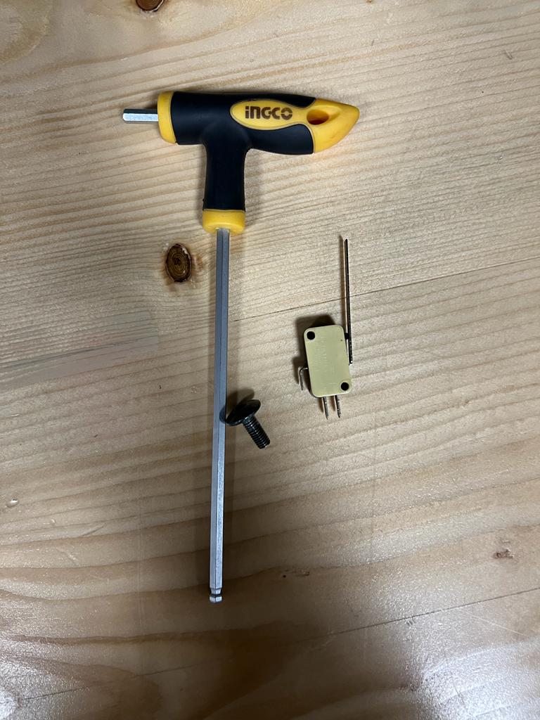
To use this switch, a bolt were attached to the engine pulley, so it will press the Limit Switch each time the engine pulley got one full round. Following, a photo for the limit swich, alinkey, and the bolt that used make the first test:-
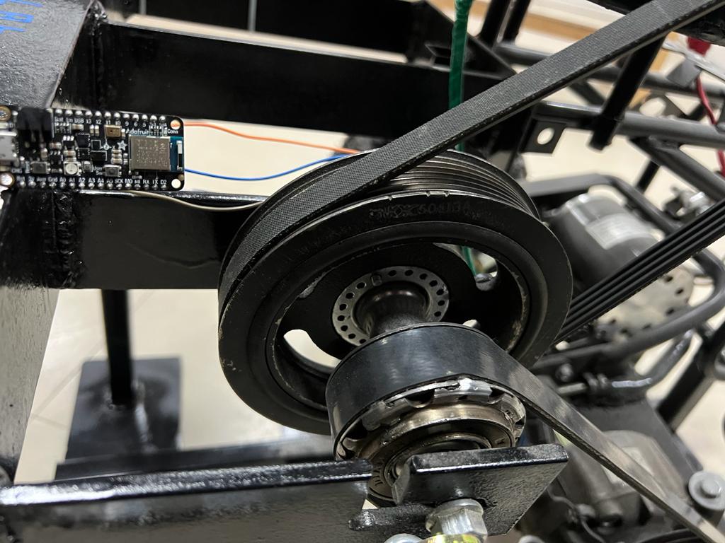
The pulley that the test will made on it:-
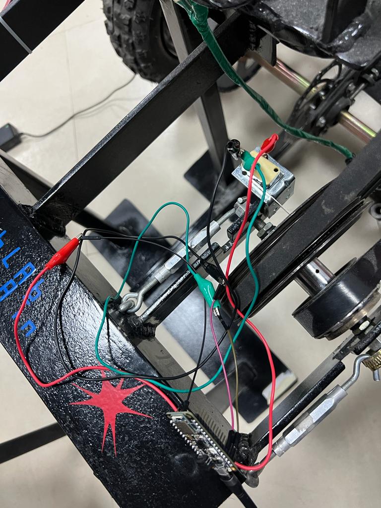
After fixing the components to the prototype, the limit switch were connected to the microconroller that will programed to count the RPM:-
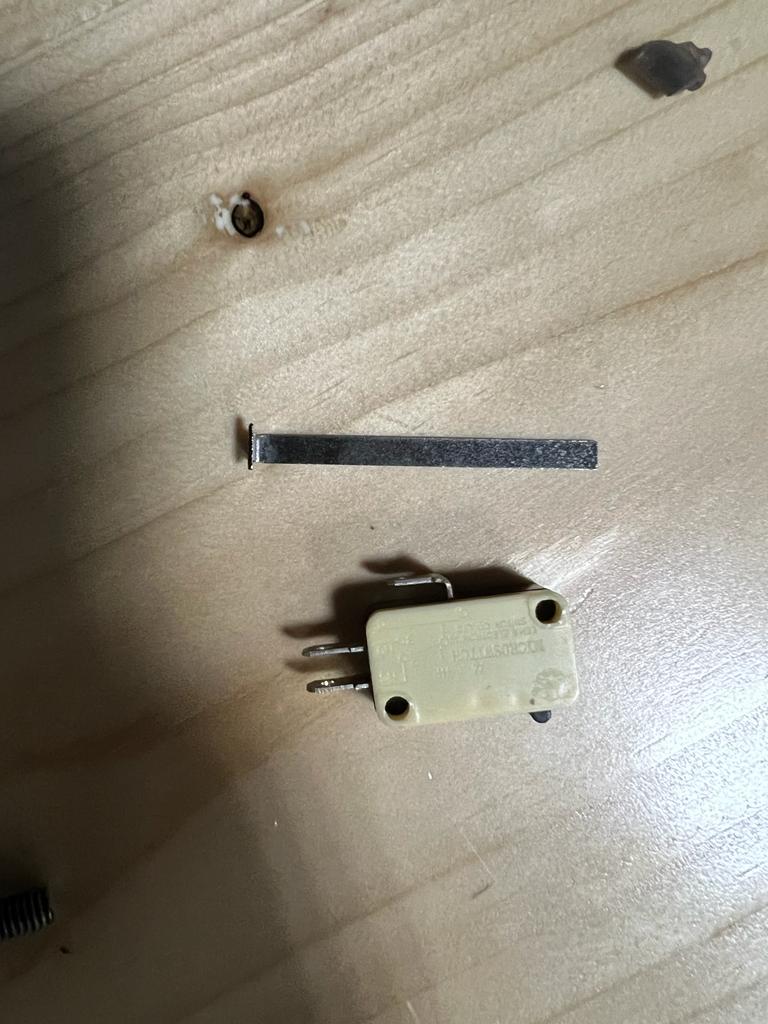
By turning on the motor and reaching a high speed, the limit switch brok and it is found that we have to find somthing else to finf the RPM:-
Magnatetic Field sensor (Test 2)
To conduct the second test, a magnatic sensor were used that can count the RPM once a magnet pass close to it. To do this test, a magnet were attached to the engine pulley while the sensor fixed into the pulley stand. After fixing the sensor, the distance between the sensor and the magnit is very important; therfore, the magnet were fix with two layres of double tape to make sure that its close enough to be detected by the sensor.
The aim of the sensor is to find the RPM of the engine pulley, by counting each time the pulley take one full rotate. Whene we conduct the test, it is found that the sensor will count up to 254 rotation then it start again from zero; therfore, the count of the RPM will be made by finding the number of rotation in 6 seconds then it will be multiblied to 10 to get the number of rotation in one minutes. Furthermore, it is found that the regenerative braking system reachs to its highest speed after 2 sucond from start running it; therfore, calculation will start after the first rotation by two second. The following code is the used code to implement all the needs from the sensor:-
#include <SoftwareSerial.h>

const byte interruptPin = 5;
volatile byte countt = 0;
unsigned long startTime;
unsigned long actualstartTime;
bool started = false;
bool actualstarted = false;


void setup() {
  Serial.begin(9600);
  pinMode(interruptPin, INPUT);
  attachInterrupt(digitalPinToInterrupt(interruptPin), blink, RISING);
}

void loop() {
  Serial.println(countt);
  Serial.println(millis());
  if (countt==1 && started == false ){
    startTime = millis();
    Serial.println("two second start");
    started = true;
  }
  if (millis() - startTime > 2000 && started == true && actualstarted == false ){
    actualstartTime = millis();
    Serial.println(countt);
    Serial.println("real  time started");
    actualstarted = true;
    countt = 0;
  }
  if (millis() - actualstartTime > 6000 && actualstarted == true ){
    Serial.println("6 seconds passed");
    actualstarted = true;
  }
}

void blink() {
  countt = countt + 1;
}
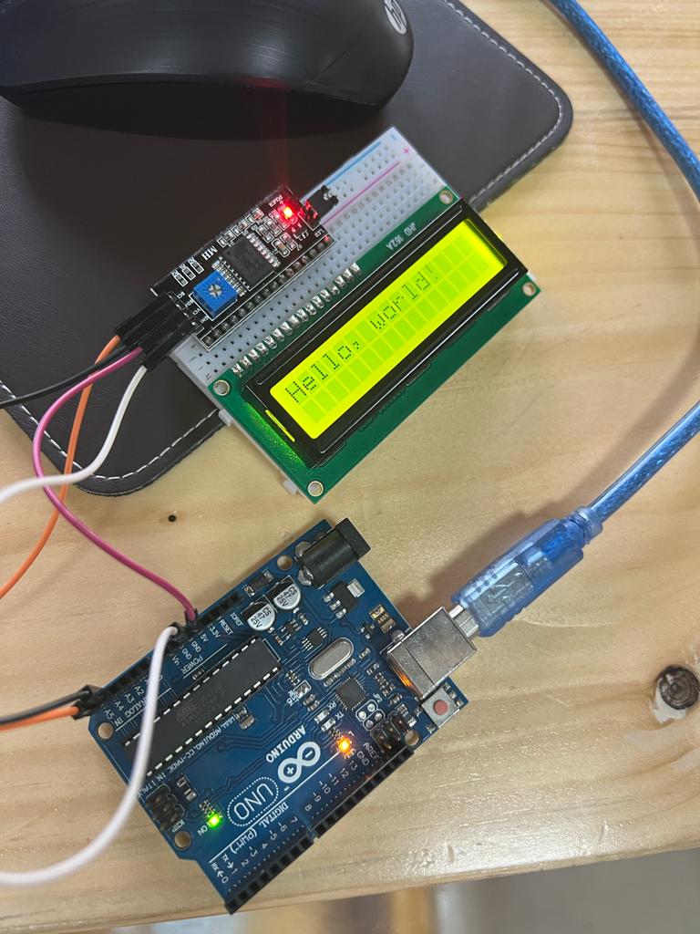
After getting an accepted result from the sensore, it is time to start programing a LCD screen to present the engine pulley RPM. Therfore, some researches were conducted to find out how to code the LCD screen. The following codes were used to test the LCD and writing (Hello, world) on the LCD screen.
#include <Wire.h>
#include <LiquidCrystal_I2C.h>

// Set the LCD address to 0x27 for a 16 chars and 2 line display
LiquidCrystal_I2C lcd(0x27, 16, 2);

void setup()
{
    // initialize the LCD
    lcd.begin();

    // Turn on the blacklight and print a message.
    lcd.backlight();

}

void loop()
{
  lcd.clear();
    lcd.print("Hello, world!");
 delay (1000);
 lcd.clear();
 lcd.print("hh!");
 delay (1000);
}
In the beginning, the LCD screen was not presenting anything, while we were sure about the code and it is correct. After checking the wires and the LCD screen we found that the LCD background light is very high, and once we dicrease the light the word start to abear.
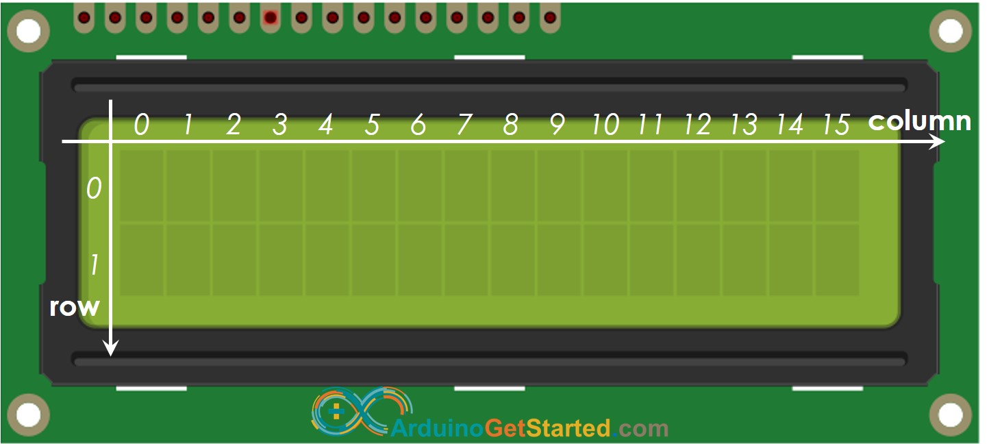
After testing the screen and the code, the code were transferd to the origenal code that were used to control the sensore. The sentance (Hello, worl) were changed with the RPM to present the calculated RPM. One of the issue faced during this step is to let the screen display a words on the first lind and the RPM on the second line. Therefore, some researches were conducted to find the way for presenting the sentance and the RPM as wanted. It is found that the LCD screen it devided to two rows and 16 column, and by finding the following photo it was easy to select the axact place to present the sentenses and the RPM:-
The following code is the final code used for the LCD screen were all the needed sentenses and the RPM kept on the corect place:-
#include <SoftwareSerial.h>
#include <Wire.h>
#include <LiquidCrystal_I2C.h>

// Set the LCD address to 0x27 for a 16 chars and 2 line display
LiquidCrystal_I2C lcd(0x27, 16, 2);

const byte interruptPin = 2;
volatile byte countt = 0;
unsigned long startTime;
unsigned long actualstartTime;
bool started = false;
bool actualstarted = false;
int rpm = 0;


void setup() {
  Serial.begin(9600);
  pinMode(interruptPin, INPUT);
  attachInterrupt(digitalPinToInterrupt(interruptPin), blink, RISING);
  // initialize the LCD
  lcd.begin();

  // Turn on the blacklight and print a message.
  lcd.backlight();
}

void loop() {
  Serial.println(countt);
  Serial.println(millis());
  if (countt==1 && started == false ){
    startTime = millis();
    Serial.println("two second start");
    started = true;
  }
  if (millis() - startTime > 2000 && started == true && actualstarted == false ){
    actualstartTime = millis();
    Serial.println(countt);
    Serial.println("real  time started");
    actualstarted = true;
    countt = 0;
    startTime = 0;
  }
  if (millis() - actualstartTime > 6000 && actualstarted == true ){
    Serial.println("6 seconds passed");
    //actualstarted = true;
    rpm = countt * 10;
    countt = 0;
    actualstartTime = millis();

   lcd.clear();
   lcd.setCursor(0,0);
   lcd.print("Engine Pulley RPM");

   lcd.setCursor(6,1);
   lcd.print(rpm);
  }

  Serial.println("-------------------------");
  Serial.print("rpm");
  Serial.println(rpm);
}

void blink() {
  countt = countt + 1;
}
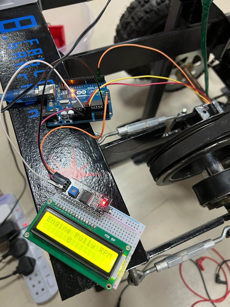
The following photo present the LCD screen after uploading the code to the microcontroller:-
After the getting the correct codes and seting, the prototye teseted again to double check the provided RPM by the sensor. The provided RPM was not regualer as when we tested it previosly, were the screen was present a fluctuated RPM as showin in the following photos:-
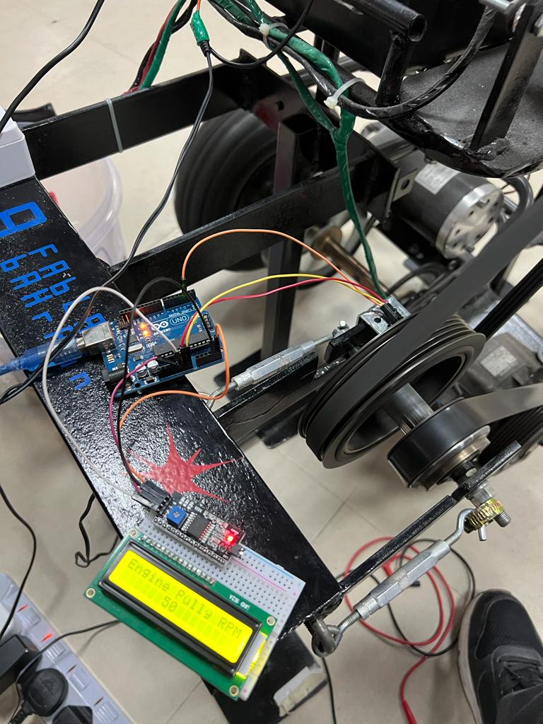
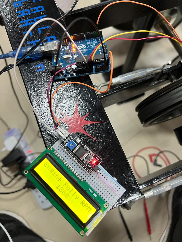
It on one actual time RPM shows that the RPM is 50RPM then it shows 1860 and the number keep changing with hugh diffrences; therfore, a double check were made to find out the proplem. It is found that the sound of the engine go high and low, the pulley speed goes up and down as will. Then it is found that the reason of these changes are caused by the car AC clutch, were the battery become very low and the clutch can not be attached very well to the pulley. To solve this problem, the battery kept on charge so it can work pproperlly on the final test.