5. 3D printing and scanning
. In the beginning of this weed, the tutors started to explain how and why we are using the 3D printers, were one of the biggest advantages of the 3D printers is the reduction on the material waste compering to the cutting machines. Moreover, several materials can be used on the 3D printers such as, PLA, ABS, Nylon, and PVA each 3D printing material has different, heat, strength, flexibility, and usage. After learning about the 3D printers a group assignment and individual assignment were given to create a 3D print specimens. Finally, after the learning and testing the 3D design, the tutors explained the 3D scanning.
Group Project - 3D printing
To start the group project, group A were divided into three groups were each group must test one of the three different 3D printers. The given task were to print a 3D design on the Ender 3D Printer, were all the 3D printers contain the same material for testing PLA. To view the final group project please visit this link.
Individual Assignment - 3D printing
The individual assignment was to create our own design to be printed on the 3D printer.
Step 1 Designing: -
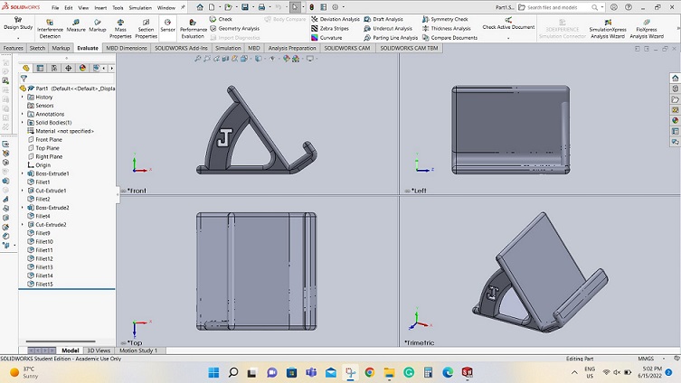
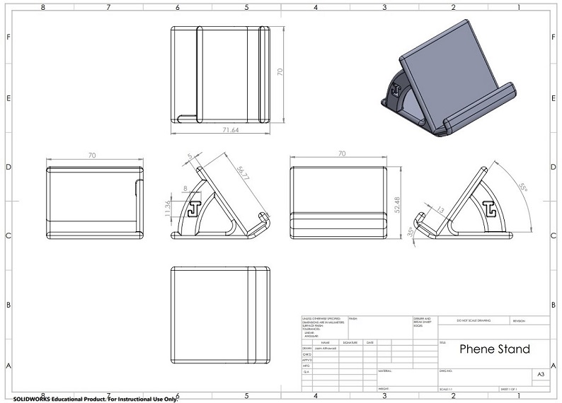
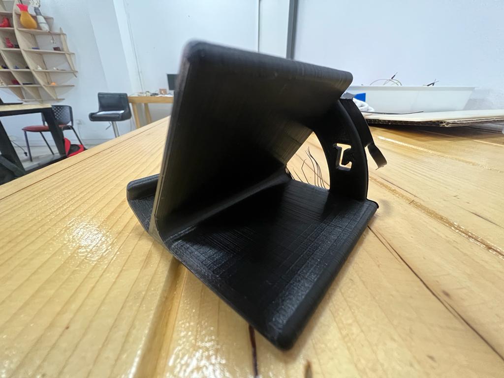
To create a 3D design, SOLIDWORK software were used. The first aim while designing was to create a useful design that can be made with minimum material waste. To reduce the waist material, the design were made to minimize the need of support during the printing. The design was made to print a phone stand, starting by taking the dimension of another phone stand to find out the suitable angle for the phone. After finding the suitable dimension, the design were sketched and extruded on the SOLIDWORKS software. As it can be seen in the following phot, the support of the stand to handle the phone weight were made on the side on the stand. The reason of providing the support on the side is to let the 3D printer start from the support side and there will be no need to create a supports so the 3D printer can print, since the 3D printer will need to provide supports of the angle of the curve is more than 45 Degree.
Please visit the following link to get the original design:
Step 2 Printing: -
Why not leaser cutter: as it can be seen in the previous design, the part shape cannot be made on a 2D leaser cutter because it has different angles and some places hard to be reached by a leaser cutter. Furthermore, if a 3D leaser cutter used to create this part, it will cause a plenty of material waist. As a result, a 3D printer selected to be used to create this design to reduce the material waist as it will be seen in the following steps.
To print the parts, the design must be saves as a STL file. Then, downloading the Ultimaker-Cura software to finalize the design for the 3D printer. By using the software, the components size, and place can be edited. Furthermore, the speed, nozzle temperature, printing plate temperature, etc can be edited and adjusted according to the used material to print the components. On our case, several designs were placed on the same printing plat to avoid the need of waiting each student to finish printing his part. Therefore, 6 designs were placed on the same time and that increase the printing time which took 1 day and 14 hours.
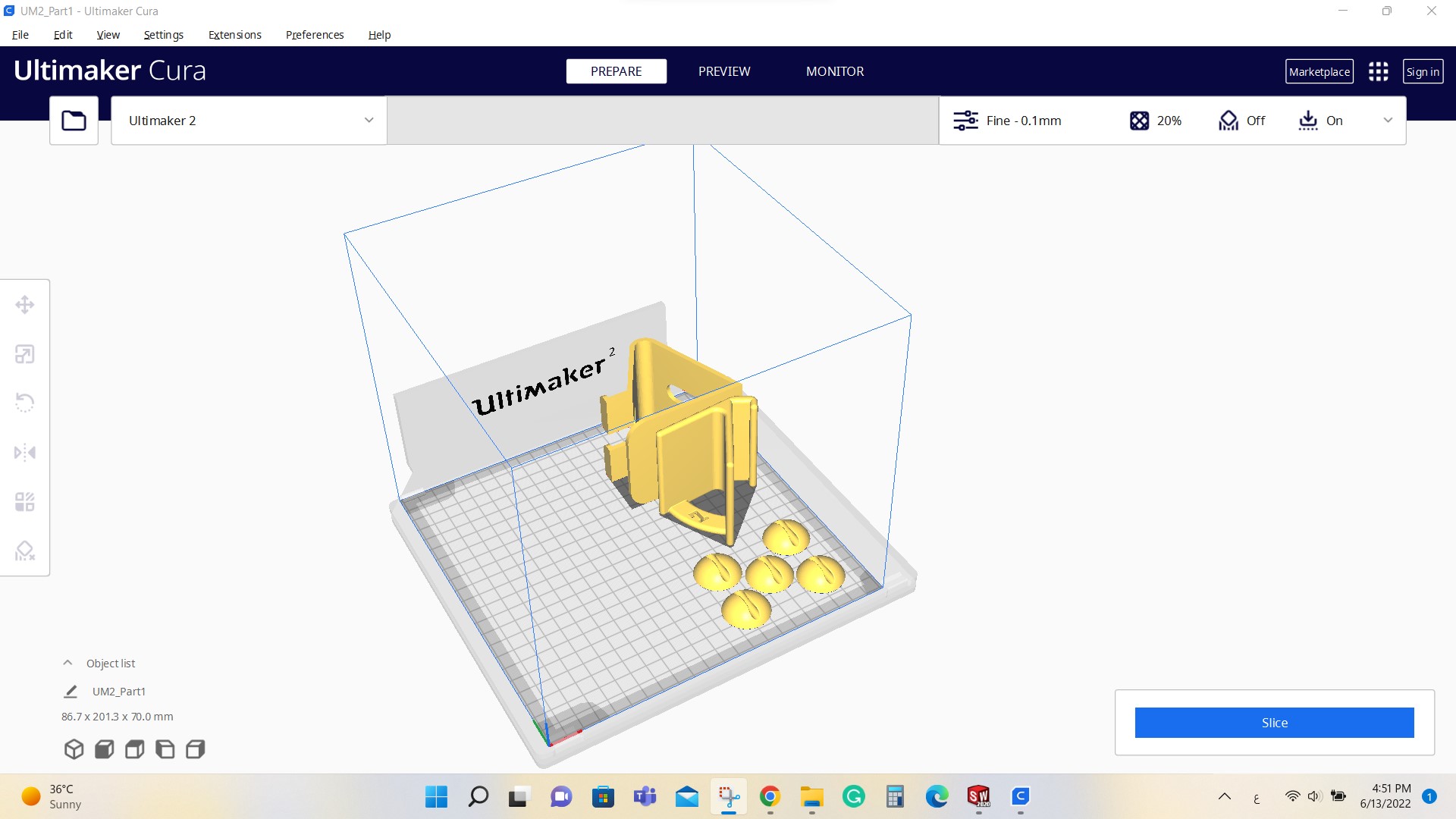 Placing the designs on one printing plate
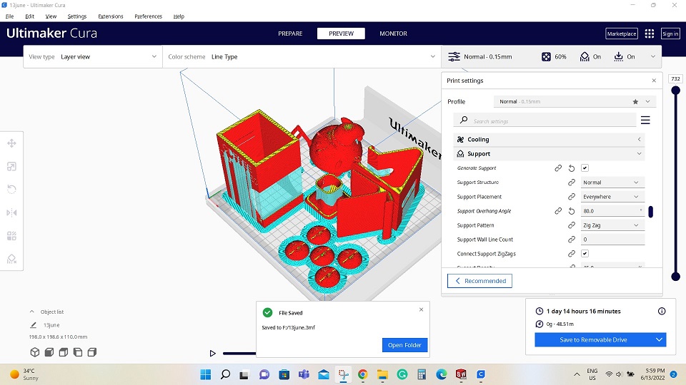 Editing the sitting and saving the file. As it can be seen in the previous photo, the light blue culler present the needed support so the 3D printer can all the parts, while the red colure present the printed part.
After saving the file from Ultimaker-Cura, the file copied to an external SSD card, that can be placed directly into the 3D Printer. Then, the saved file selected by using the 3D printer screen to start the printing.
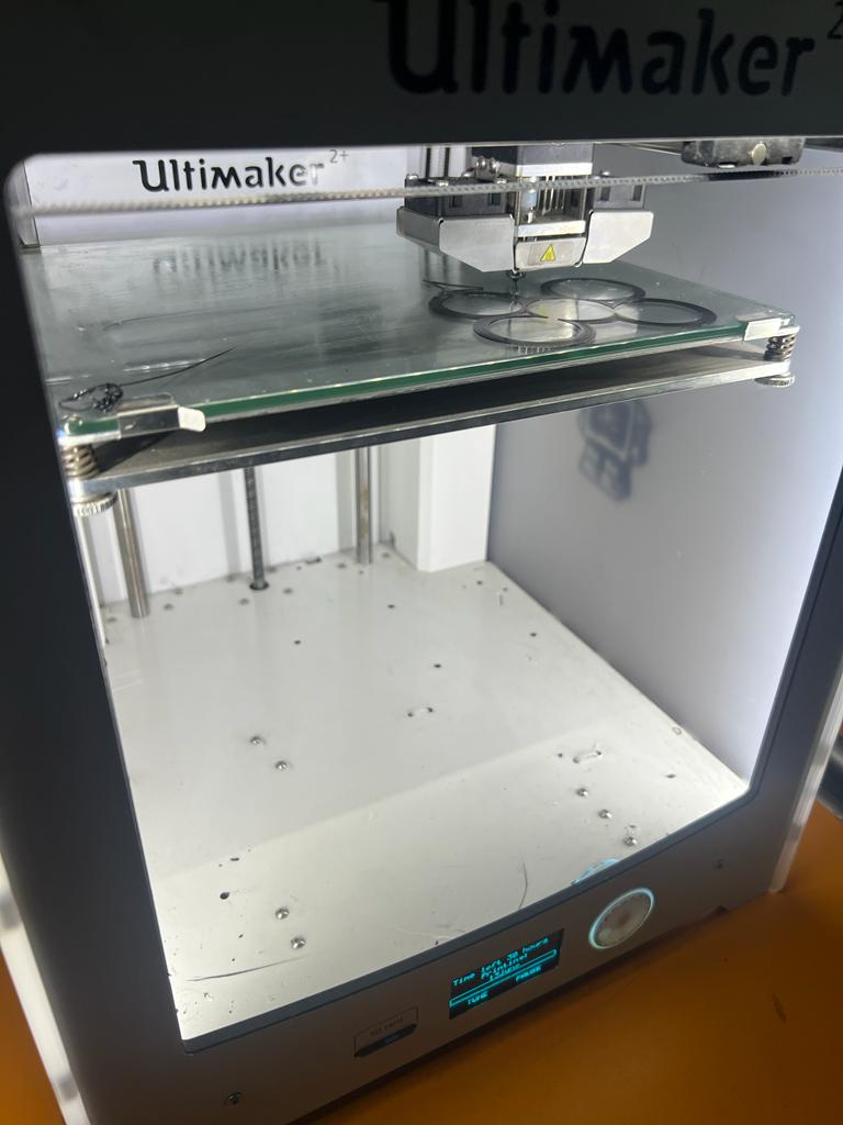
The bellow photo present the progress of the 3D printer after approximately 14 hours of working: -
Step 3 Machining: -
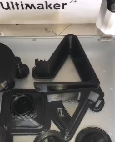
After the printer finish from printing the parts, the parts were include tome of the supports as it can be seen in the following photo: -
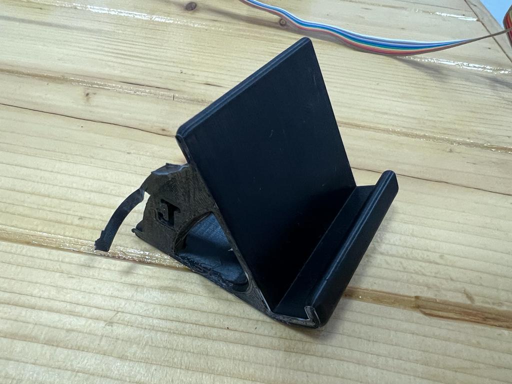
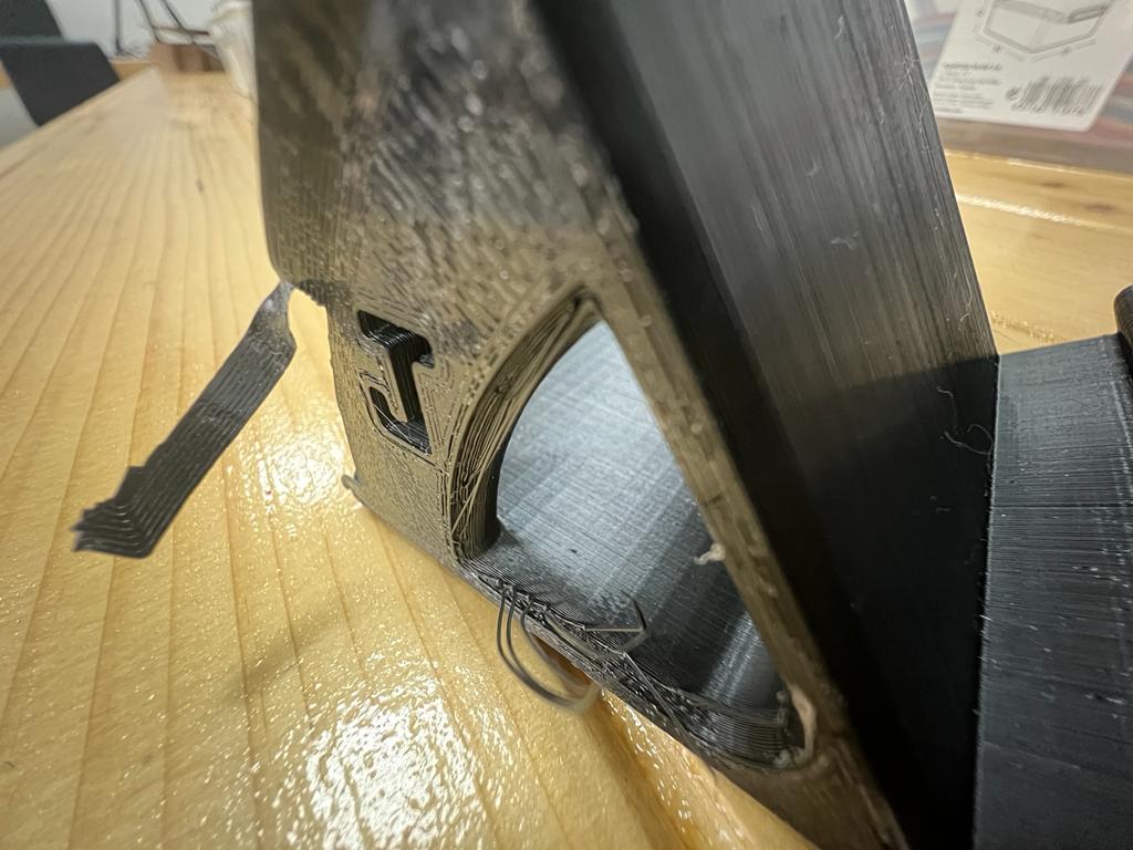
The supports are unwanted material that was provided to support the part during the printing to ensure that the part will not move. Therefore, a sand paper were used to remove the unwanted material to get smother and clear shape for the part as it can be seen in the following photos: -
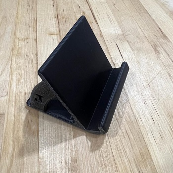
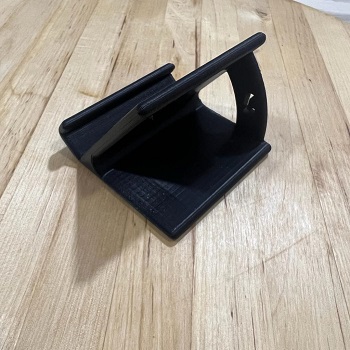
The final result of the printed part is accepted since the whole part printed properly with clean and clear service. But, the cleaned side by the sand paper is not clear and clean as the rest of the part body.
After testing the 3D printers on the group assignment and the individual assignment, some points were learned as following:- - It is important to evaluate you design to find out if it is better to use 3D printer or to use different machines. - The type and the quality of the 3D printer can make a lot of Deference in the part. As the quality of the machine increase, a better part with a great finishing will be found. - While designing the pars, it is important to think how this part will be printed, this will may decrease the need of adding support to the part to be printed which will result in less material waist while printing. - Before starting to print the part, it important to check the printer nozzle to make sure there is no stuck material that will effect the printing process. Moreover, it is important to clean the 3D printer tray before printing to make sure that it is clean and ready to print on it. - It is important to check the recommended speed and temperature of the nozzle and the hotbed to avoid any damage that can be occur to the printed pert. - After printing the part, it will still need to be machined to be cleaned from the additional part that was added to the part to fix it to the 3D printing hotbed to avoid any movement while printing the components. - Some part may takes hours or even days to be printed; therefore, it is important to make sure of the availability of the power supply. Some 3D printers can pressed working on the part if its unplug to the electricity and then plugged again, while large number of 3D printers will start from the beginning and the previous work will be lost.
Individual Assignment - Scanning
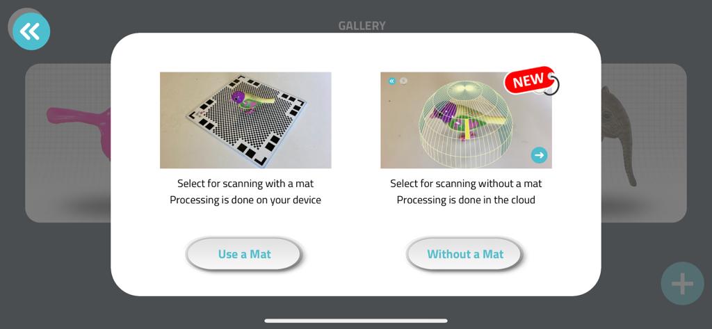
3D scanning is a new way of scanning which was found very interesting were it provide a 3D view for the component from all the sides. To scan the components, phone software were downloaded called Qlone. The software provide an easy way to scan the components, were two ways are provided that scanning with mat and without mat. It is recommended to use a mat while scanning the components to get more clear scanning.
Moreover, it is recommended to use a rotating stand like rotating chair or rotating cake stand. While experimenting the 3D scan, a rotating cake stand where used: -
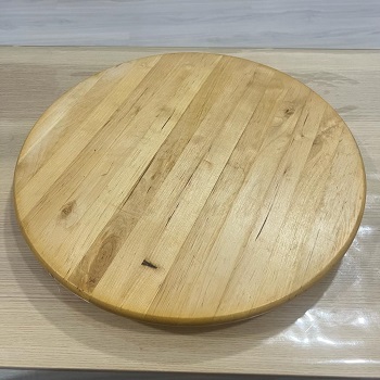
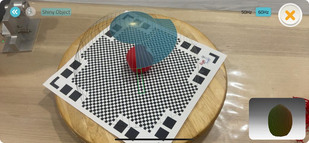
which used to place the mat and the component and provide a smooth rotating for the mat with the components. While scanning, a blue circle will be presented over the part, where the mat and the part must be rotate to complete the whole circle as presented in the following photo: -
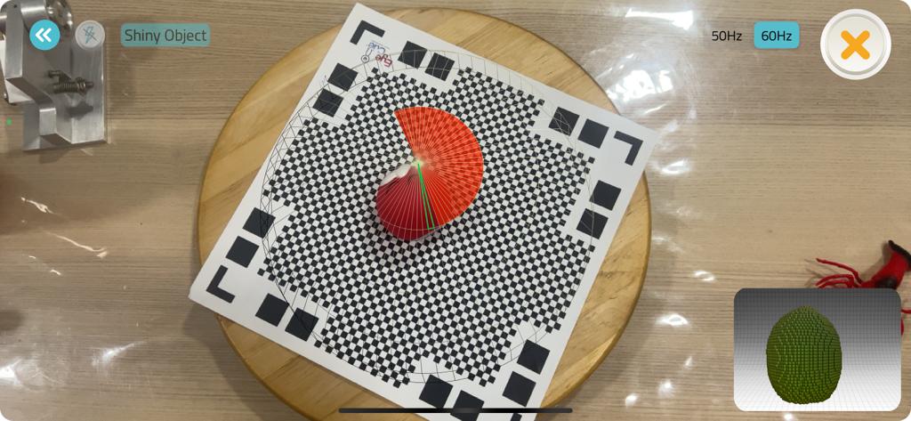
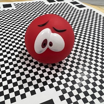
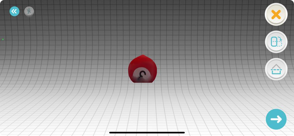
 Moreover, if the phone went fare a way from the part then a red circle will be presented, which mean that the program cannot scan properly and the phone must be more closer to the part as presented in the following photo: -
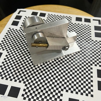
Several components were tested with the 3D scanning, bellow the component and its 3D scanning is provided: - - Steam Engine
Actual parts:
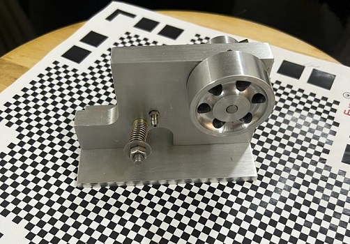
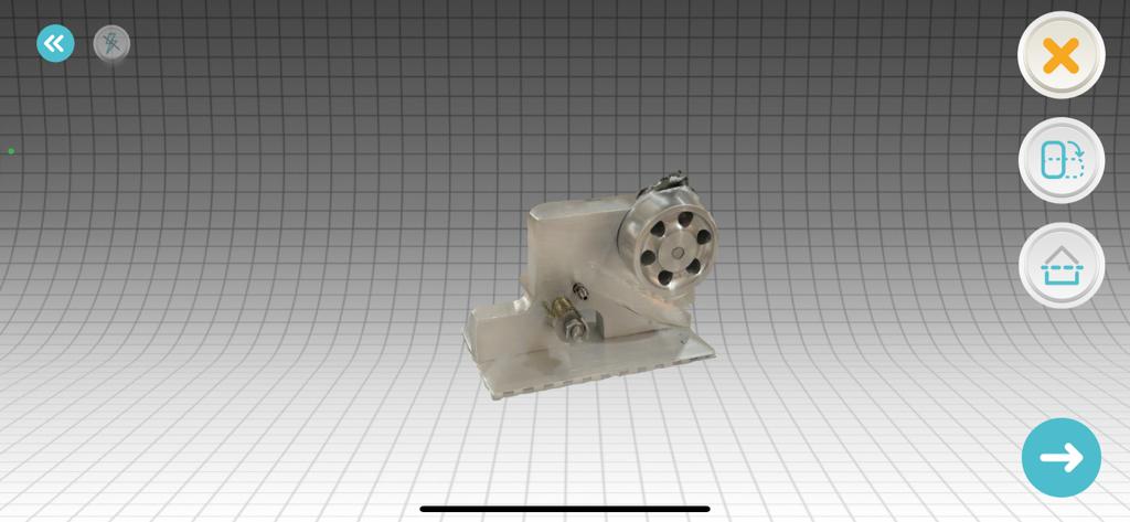
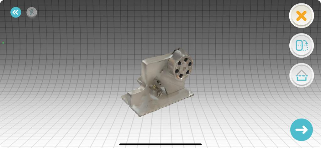
Scanned part:
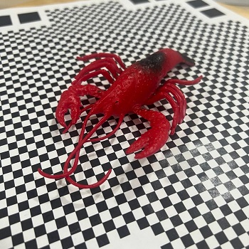
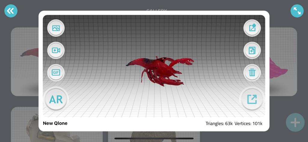
- Lobster
Actual part:
Scanned part:
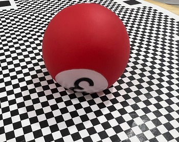
- Ball
Actual parts:
Scanned part:
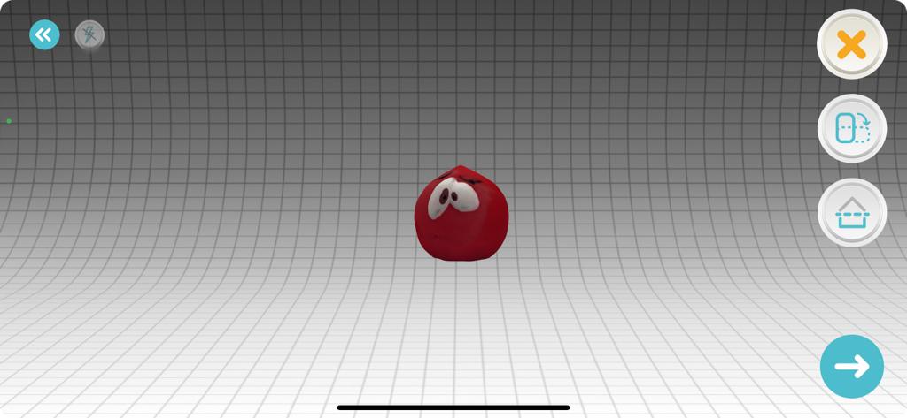
As it can be seen n the previous photos, the steam engine scan was good for some parts and it was unclear on some parts; therefore, the lobster and the ball where scanned after and it were scanned properly. That shows that as the part do not has a deep holes and has more clear service the scan will be more clear.