Final Project (Regenerative braking)
Before start to design the final project, a main low must be kept on mind to achieve the aim of the prototype. As per the first low of thermodynamic (conservation of energy) “Energy can neither be created nor destroyed”. By following this low, the prototype will be designed and manufactured to convert energy from one form to another. The regular braking system for vehicle used to reduce the vehicle speed, the reduction on the vehicle speed can be made by converting the kinetic energy in the drive shaft and wheel to heat energy to be spread in the atmosphere without any benefit of the spread energy. Thus, the main feature of the regenerative braking is to recover some of the energy by convert the kinetic energy to electric energy instead of converting it all to heat energy.
Final Project components
The prototype designed will not be scaled down and it will be provided design to be used for electric quad or any hybrid/electric vehicles. The design can be scaled up for large vehicle or scaled down for smaller vehicle.
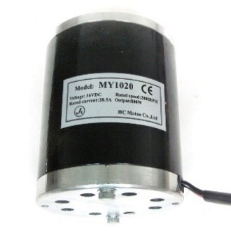
Electric motor
An electric motor wear selected to provide the needed power to run the system. Where an 800W electric motor will be used that run with lithium-Ion batteries. The selected motor runs at 2800RPM, where the outlet connection is a small sprocket with 11teeth.
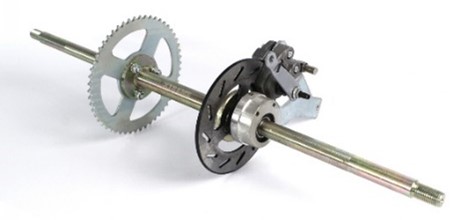
Drive shaft with large sprocket
A rear electric quad shaft where selected to be the drive shaft. The selected shaft is 560mm length, that provide more space to attach additional components on it if needed. To connect the drive shaft with the motor, a large sprocket with 64teech is provided with the shaft that will provide a high torque to drive vehicle.
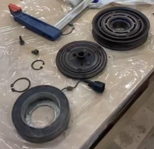
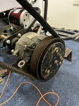
Car A/C compressor clutch
The A/C compressor clutch were selected since it can be connected and disconnected easily. There are three main parts in the A/C clutch which are coil, pully, and clutch. The coil is fixed on the compressor, and it is connected to the batteries. The pully is assembled over the coil, and it will provide a free spinning over the compressor body. Finally, the clutch which is connected to drive shaft and has small clearance between it and the pully. In the A/C compressor, the pully spins when the engine turn on, but the compressor will be disconnected by disconnecting the coil from the electricity. When the drive turns on the A/C, the electricity will be provided to the coil, and it will provide a magnetic field to attach the clutch to the pully to run the compressor. The diameter of the clutch pully is 134.4mm, that will give the ability to increase the speed.
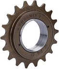
Bicycle rear sprocket
The rear sprocket of the bicycle was selected because of its mechanism. The main mechanism of rear sprocket is to rotate on one direction, while in the other direction it will not affect the shaft. This feature of the sprocket will allow power to transfer from the A/C clutch to the flywheel (engine poly). Moreover, if the flywheel has high power (spins in high RPM) and the drive shaft has less power (spins in low RPM) then if the driver turns on the system, then the flywheel power will not transfer to the drive shaft.
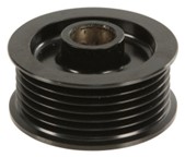
Alternator pully
Since the clutch of the car A/C is a pully, then an alternator pully where selected to be attached with the sprocket. This attachment will provide the mechanism of the bicycle sprocket and will allow to use a belt to connect the car A/C compressor clutch and the sprocket. The diameter of the alternator pully is 57.35mm, that will give the ability to increase the speed.
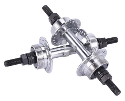
Connecting shaft
A bicycle rear axle where selected to be used for the prototype since the bicycle sprocket can be attached to it easily by the thread part. Furthermore, the axel will contain a shaft and bearing to connect the shaft on the prototype body and the bearing with its sprocket and pulleys can spin smoothly.
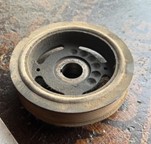
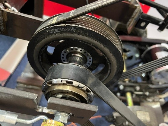
Engine Pully
On the same shaft with the bicycle sprocket, an engine pully where selected since it has high weight and large diameter. The high weight of the engine pully will allow it to store some of the provided power while applying the brakes. Moreover, since the engine pully will rotate at the same speed of the bicycle sprocket, then the large diameter will allow to increase the speed that will be provided to the next part. The diameter of the engine pully is 134.4mm, that will give the ability to increase the speed.
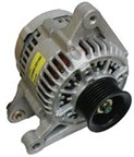
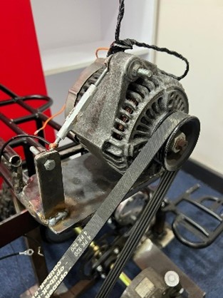
Car Alternator
A car alternator was selected to produce electricity by the provided power by the system. The alternator provides electricity by converting the mechanical energy to electrical energy, where the rotor will start spinning inside the stator to provide the electricity. To start the alternator, an external electricity needed since the alternator needs for excitation to provide electricity. To check the alternator, a light is connected by both terminal to the alternator with will be connected to the battery. The light will glow while the alternator is stop, but once the alternator starts to spin and provide electricity, the light will switch of automatically and the voltage will increase to charge the batteries. The pully of the car alternator has small diameter comparing to the engine pully, thus will increase the spinning speed where the alternator needs for high speed to provide an electricity. The diameter of the alternator pully is 57.35mm, that will give the ability to increase the speed. The increase of the speed is required since the alternator need to spin at about 2400RPM.
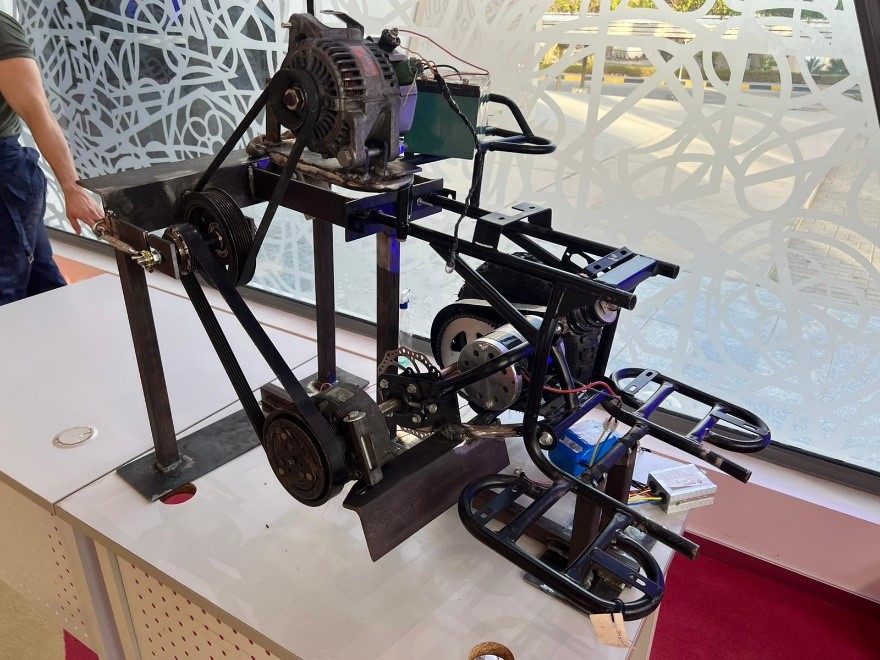
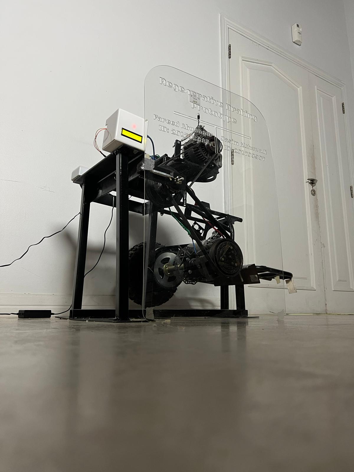
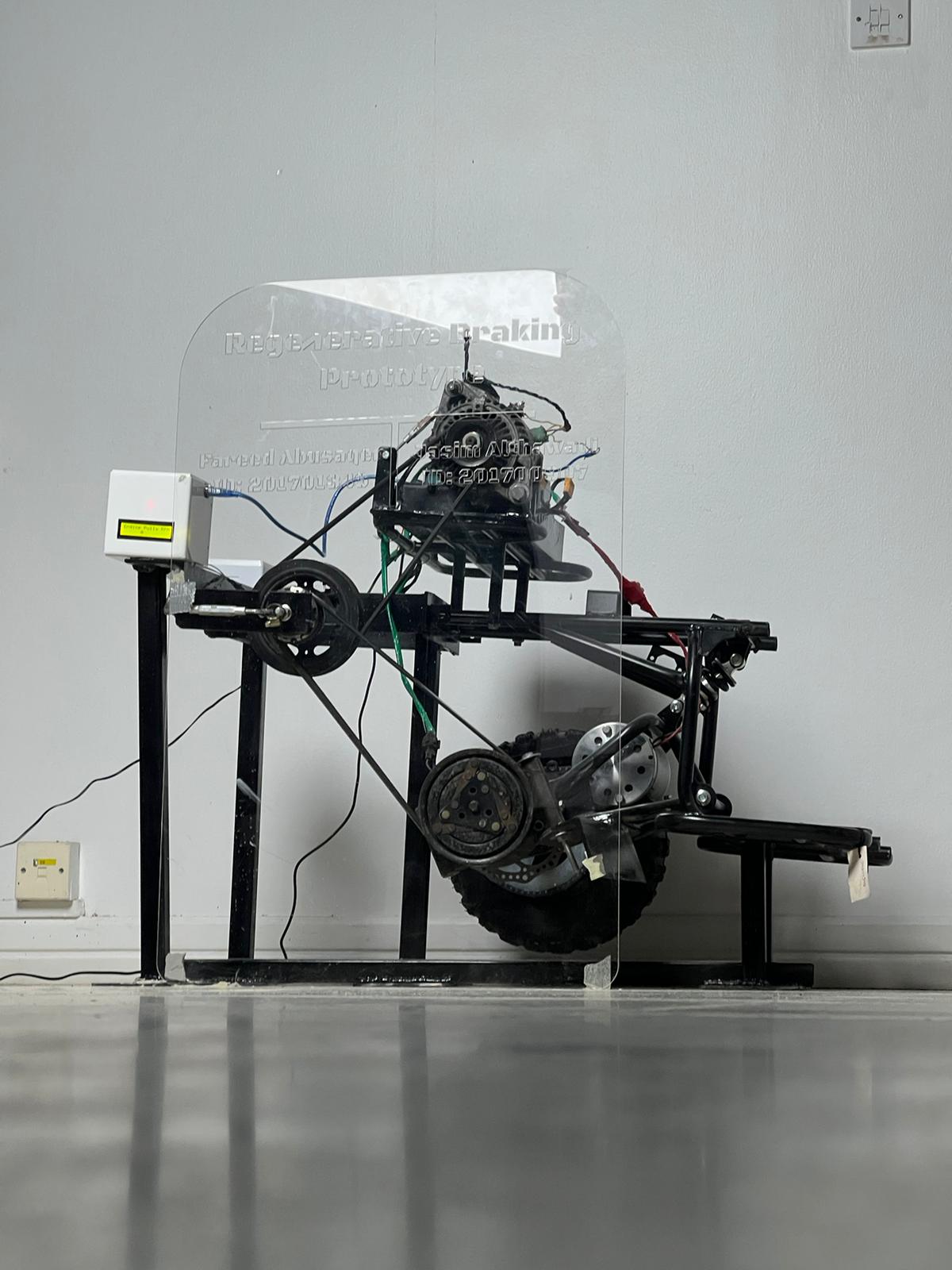
Final Project Design
By using the previous components, the connection between the components will be as presented in the bellow :-
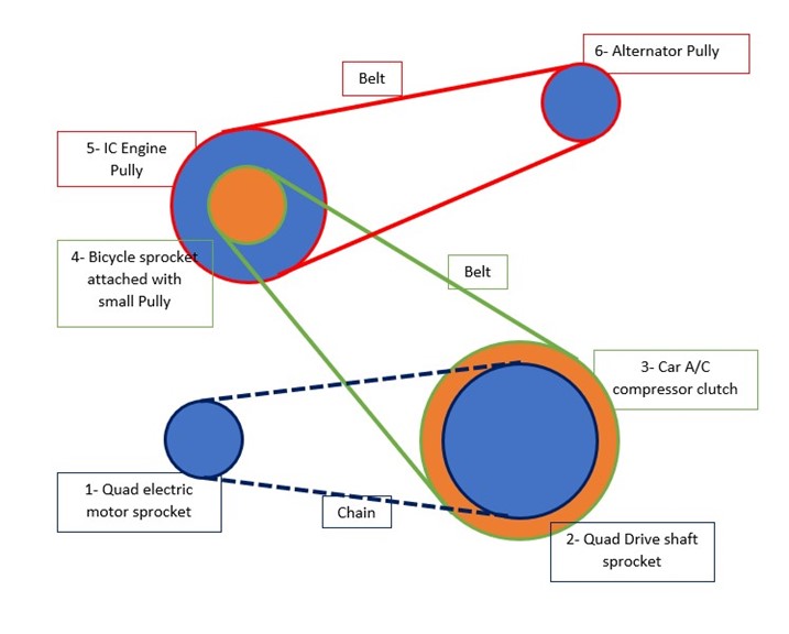
As it can be seen:-
1- The Electric motor is connected by a chain with the large sprocket on the drive shaft.
2- The car A/C clutch is attached directly on the drive shaft; hence, it has the same RPM speed of the drive shaft.
3- The car A/C clutch is connected with the bicycle sprocket (attached with small pully) by a belt.
4- The bicycle sprocket is attached directly to the IC Engine pully since both are on the same shaft.
5- Finally, the IC Engine pully is connected with the alternator pully by a belt.
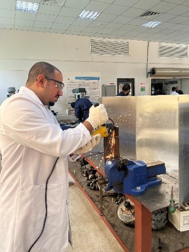
Manufacturing Process
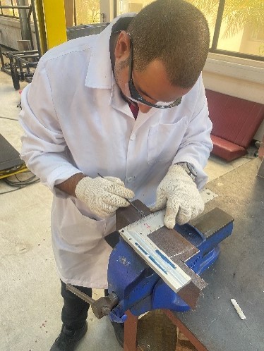
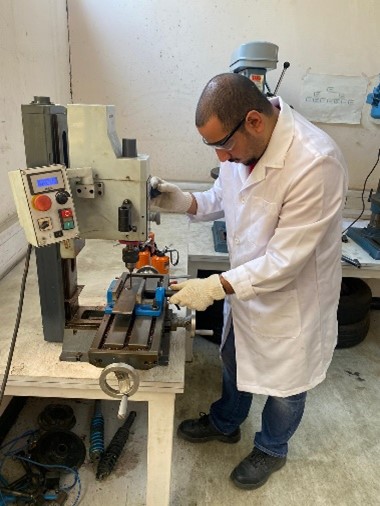
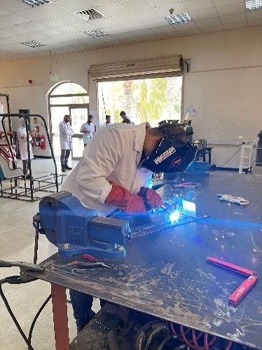
The design and components were provided for the project partner to find out the suitable way to manufacture the needed part to achieve the designed system. Then, the manufacturing process started by taking the permission to use Bahrain Polytechnic mechanical lab. The manufacturing process started by collecting the needed beams and sheets according to the needed dimensions. Before cutting, drilling, or doing any changes in the parts, the part was measured twice by both partners to avoid any losses on the parts. Then the parts were divided on the partners to be manufactured according to the dimensions.
System speed calculation
Theoretical calculations
To calculate the theoretical speed of the components, the speed of the electric motor will be used. Furthermore, the number of teeth for each sprocket and the diameter of each pully will be needed to find out the component that has speed reduction and the components that get higher speed. To calculate the components speed, the following equation will be followed: -
Input speed (N1)/Output speed (N2) = Output number of teeth (T2)/Input number of teeth (T1)
Or
Input speed (N1)/Output speed (N2) = Output diameter (D2)/Input diameter (D1)
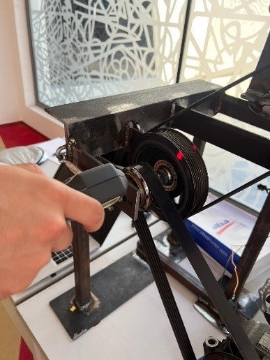
Experimental calculation
A tachometer will be used to get the experimental speed for the components. Then a comparison will be conducted to compare the theoretical speed with the experimental speed of the components.

Speed comparisons
First, the theoretical speed will be compared with the experimental speed while the alternator does not generate electricity, to find out the actual speed that the system can provide it to the alternator. Then the theoretical speed will be compared with the experimental speed while the alternator generates electricity.
Speed Deviation=(Theoretical speed-Experimental speed)/(Theoretical speed)×100
Regenerative Braking Efficiency
The efficiency of the prototype will be found by measuring the voltage and current by multimeter that provided by the alternator. The values will be used to calculate the power provided by the alternator, then it will be compared to the experimental motor power to find out the efficacy of the regenerative braking system. The reason of using the experimental electric motor power instead of the theoretical power is to find out the losses that occurred by the system.
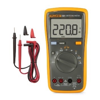
To calculate the power of the motor and the alternator, Ohms low will be used: -
Power (P)=Current (I)×Voltage (V)
After calculating the experimental power that the alternator can generate it, a deviation between the experimental electric motor power and the experimental alternator power will be made by using the following equation: -
Power Efficiency= (Alternator power)/(Motor Power)×100
Manufactured regenerative braking
System speed calculation
Theoretical calculations
Motor speed (N1) = 2800RPM
Motor sprocket number of teeth (T1) = 11 teeth
Drive shaft sprocket number of teeth (T2) = 64 teeth
Car A/C compressor pully (D1) = 134.4mm
Sprocket with small pully (D2) = 57.35mm
Engine pully (D3) = 134.4mm
Alternator pully (D4) = 57.35mm
Drive shaft sprocket speed (N2):-
(Motor speed (N1))/(Drive shaft sprocket speed (N2))=(Drive shaft sprocket teeth (T2))/(Motor sprocket teeth (T1))
2800/(N2)=64/11
N2=481.25RPM
∵ The drive shaft sprocket and the clutch pully are attached on the same shaft
∴ Clutch pully speed is equal to dive shaft sprocket speed (N3) = 481.25RPM
Bicycle sprocket with the small pully speed (N4): -
(Clutch pully speed (N3))/(Bicycle sprocket with pully speed (N4))=(Bicycle sprocket with pully diameter (D2))/(Clutch pully diameter (D1))
481.25/((N4))=57.35/134.4
N4=1127.812RPM
∵ The bicycle sprocket with pully and the engine pully are attached on the same shaft
∴ Engine pully speed is equal to bicycle sprocket with pully speed (N5) = 1127.812RPM
Bicycle sprocket with the small pully speed (N4):-
(Engine pully speed (N5))/(Alternator pully speed (N6))=(Alternator pully diameter (D4))/(Engine pully diameter (D3))
1127.812/((N6))=57.35/134.4
N6=2643.033RPM
As per the calculated speed, the final speed that the alternator will receive to produce the electricity is 2643RPM, this speed can cover the requirement of the alternator which is 2400RPM. Moreover, this speed will be compared with the experimental speed that will be found later.
Experimental calculation
Spinning speed without generating electricity
(RPM)
Drive shaft (N2 and N3) = 473
Connecting shaft (N4 and N5) = 1041
Alternator (N5) = 2454
Spinning speed with generating electricity
(RPM)
Drive shaft (N2 and N3) = 428
Connecting shaft (N4 and N5) = 916
Alternator (N5) = 2209
As it can be seen in the previous calculation, there are two speeds for each component, one for the speed of the components while the alternator is not generating electricity and second while the alternator generates electricity. It is clear, that the speed of the components while the alternator does not generate electricity are higher than the components speed while the alternator generates electricity. This obvious difference in spinning speed is caused by the increment on the alternator resistance to generate electricity. Furthermore, the alternator will need for excitement to produce electricity and it is found when the batteries voltage is low (5.6V) the alternator will not generate electricity, but when the batteries changed with 12V batteries, the alternator start to generate electricity. Moreover, the alternator resistance increases when the current is increase.
Speed comparisons
Following, the deviation between the theoretical and experimental speed will be calculated by the deviation equation:-
Deviation = (Theoretical speed-Experimental speed(without electricity))/(Theoretical speed)×100
Components deviation without generating electricity:
Drive shaft deviation:
Deviation Drive shaft=(481.25-473)/481.25×100=1.7%
Connecting shaft deviation:
Deviation Connecting shaft=(1127-1041)/1127×100=7.6%
Alternator deviation:
Deviation Connecting shaft=(2643.0.33-2454)/2643.033×100=7.2%
Components deviation without generating electricity:
Deviation=(Theoretical speed-Experimental speed (with electricity))/(Theoretical speed)×100
Drive shaft deviation:
Deviation Drive shaft=(481.25-428)/481.25×100=11.1%
Connecting shaft deviation:
Deviation Connecting shaft=(1127-916)/1127×100=18.7%
Alternator deviation:
Deviation Connecting shaft=(2643.0.33-2209)/2643.033×100=16.4%
Speed deviation Discussion
As it can be seen in the previous calculations the prototype efficiency in respect to the change in speed between the different components is accepted, since the deviation between the theoretical and experimental without generating electricity speed are less than 2% between the two sprockets and less than 8% in connecting shaft and the alternator. The deviation between the motor sprocket and the drive shaft sprocket can be caused by losses in the chain that connect both sprockets. Furthermore, the deviation between the theoretical and the experimental value for the connecting shaft and the alternator pully can be caused by different reasons such as, loss in the engagement between the car A/C clutch and the pully, friction in the connecting shaft and its bearings, slipping the belt over the pulleys, and it can be caused by human error by not tighten the belt well and while measuring the speed rotation for each component by using the tachometer. In addition, the deviation between the theoretical and the experimental speed while the alternator generates electricity is higher than 10%. This increment on the deviation between the theoretical and the experimental value is accepted since the resistance of the alternator will increase while it generates electricity; thus, the presented causes of the deviation will increase because of the added resistance.
Regenerative Braking Efficiency
To calculate the efficiency of the system, the electric motor power will be calculated to be used to compare it with the alternator provided power. The power provided by the alternator will be calculated as following:-
Motor Power (P)= Current (I) × Voltage (V)
Motor Power (P)=11.5×36
Motor Power (P)=414W
The power provided by the alternator will be calculated as following:-
Alternator Power (P)=Current (I)×Voltage (V)
Alternator Power (P)=10.6×13.95
Alternator Power (P)=147.87W
The provided power by the motor is equal to 410.4W, this experimental power will be compared with the experimental power of the alternator which is 147.34W.
Power Deviation= (Alternator power)/(Motor Power)×100
Power Deviation= 147.87/414×100
Power Deviation= 35.7%
As it can be seen, the deviation between the motor power and the alternator power is equal to 35.7%; therefore, the prototype can be accepted as it is the first design for the prototype since the actual regenerative braking that manufactured by the heugh manufacturer has 70% efficiency. This differences between the motor power and the alternator power can be caused by the batteries ability to charge, since the used batteries are 14amh which may not be efficient to receive high current. In addition, the percentage of the batteries capacity makes different on the current flow, were if the batteries are close to be fully charge, then the current flow will be reduced while if the batteries are empty then it will increase the current flow.
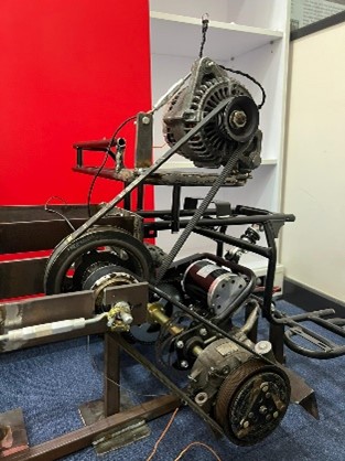
Acrylic Protection
The prototype were presented on Bahrain Polytechnic recruitment Expo, and it was found that we have to add protection to cover the belt side. Therefore, an Acrylic sheet ere cut by the laser cutter to protect people how come close to the prototype to get closer view.
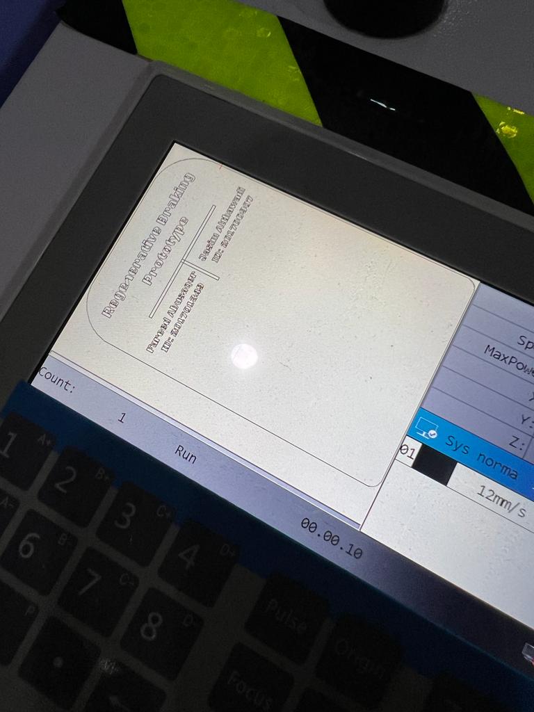
As a result, a design were made to cut the acrylic to provide the needed protection and to present the project group members names. The design was made by using Inkscape software by taking the maximum size that the laser cutter can cut to cover the maximum area on the built side. After siting the dimension, then the names were pleased on the top of the protection. Then the design sent the computer that connected to the laser cuter and edited there. After checking the design and on the laser cutter screen as presented below:-
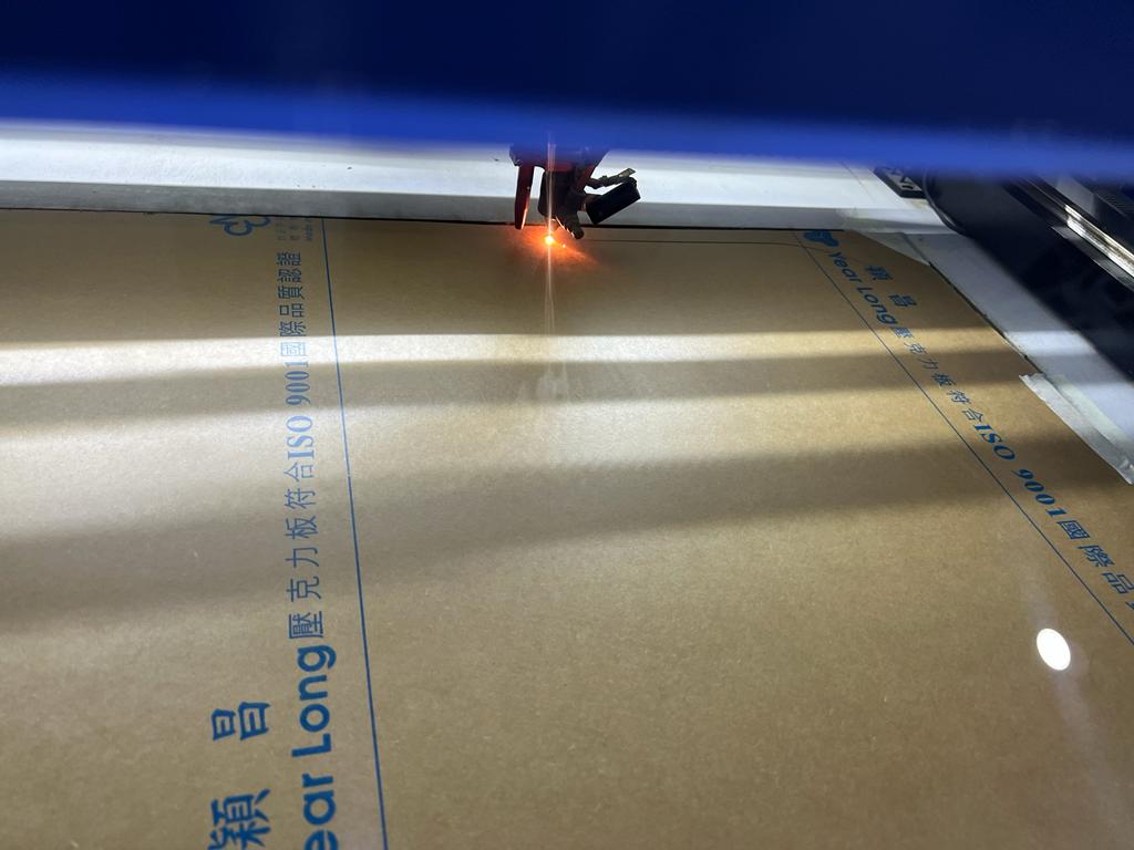
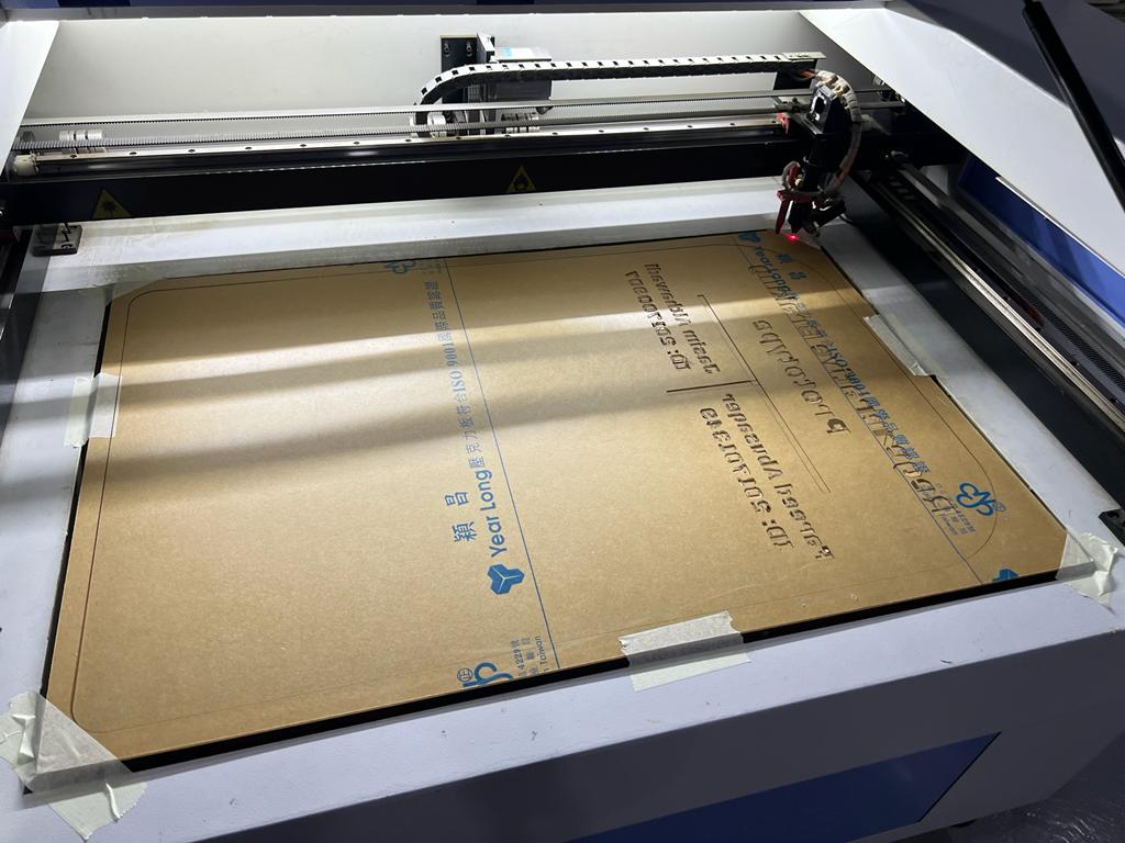
The laser cutter start to cut the acrylic sheet to provide the final protection components:-
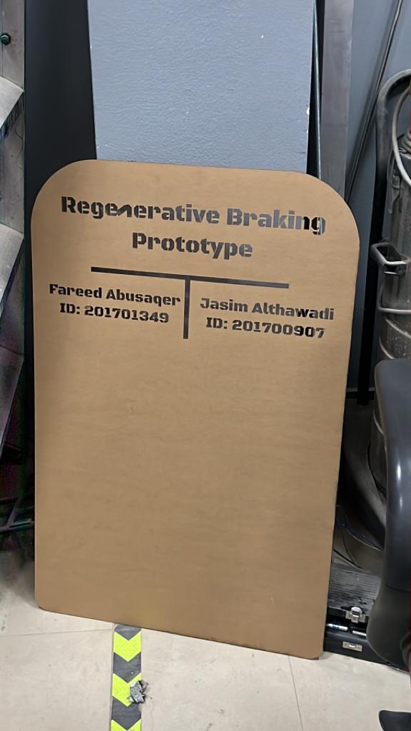
After the laser cutter done from cutting the protection, the part removed carefully from the laser cutter and paper sheet removed.
Finally the protection attached to the prototype by using a double tape
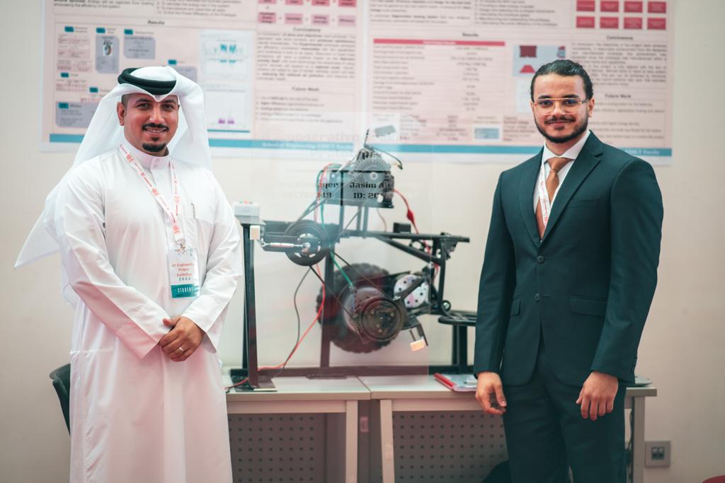 The previous photo present the group members while presenting the prototype on the Engineering exhibition at Bahrain Polytechnic.
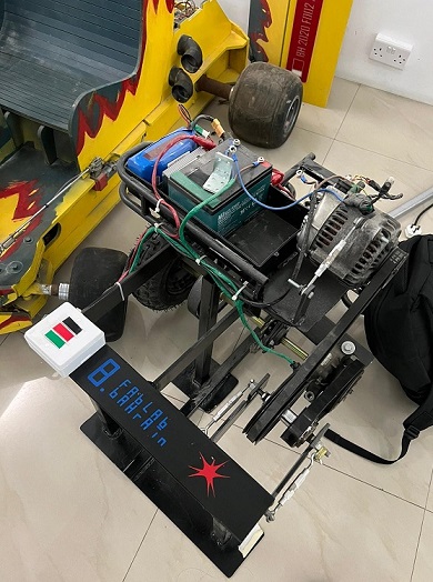
Vinyl Sticker
After adding the protection to the regenerative braking system, a new plan to present the logo of main supporters to complete the project on the prototype. Therefore, the logo of FabLab Bahrain and Bahrain Polytechnic used to create a sticker to be stacked on the prototype as it can be seen in the following photo:-
To get more details about the followed proces, please visit this link.
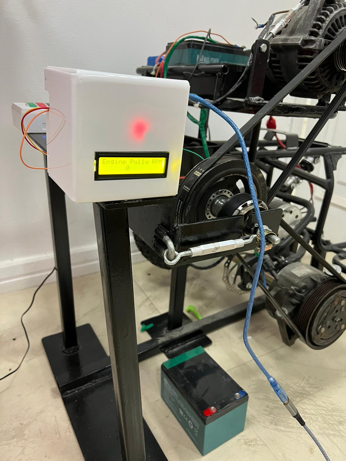
RPM Indicator
After manufacturing and testing the regenerative braking, a new idea rise to provide a sensor that count the Engine Pulley RPM. After compleeting the test that conducted on week 7, the best way to count the engine polley RPM is by using a magnatic sinsor. Therfore, a megnatice sinsor used to indicate the engine pulley RPM by counting each time the magnet pass in front of the sensor. All details abount the magnatec sensor and can be found in the following link and more details about other tests that conducted for the RPM indicator can be found in this link.
After making sure that the magnatic sensor is counting the engine pulley RPM correctelly, an acrylic bax have been made to hold the LCD screen. Then, the box that holding the LCD screen and the other combonents placed on the side of the prototype to present the RPM for the odiance as it can be seen in the following photos.
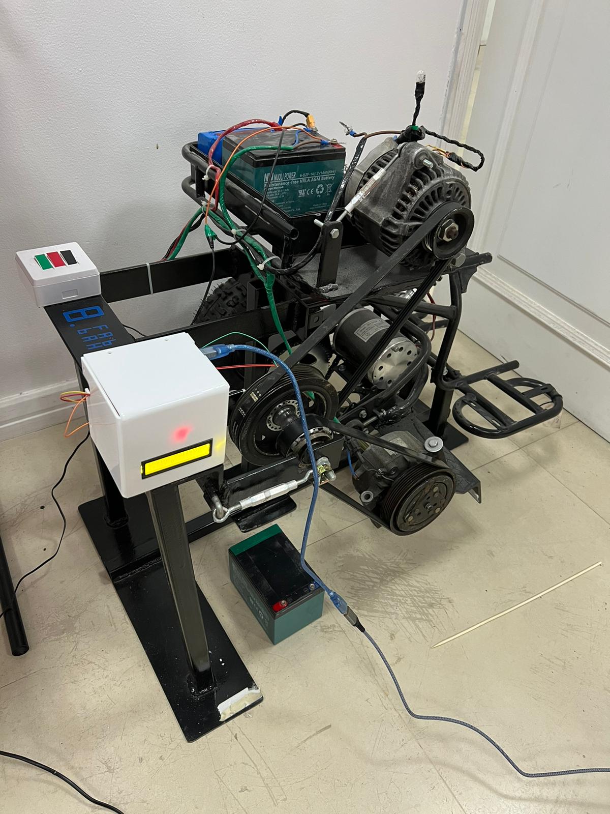
Finally, the sensore was tested again to make sure that every thing is working properlly and a hero shoots were taken for the final prototype:-
The following video prisent the prototype while its working and the RPM can be seen in the video:-

Or you can visit the following link