5. Emdebbed Programming
This week, I explored two different programming software to work on an electrical chip called Arduino nano for various applications.
Microcontroller
A microcontroller is embedded inside of a system to control a singular function in a device. It does this by interpreting data it receives from its I/O peripherals using its central processor. The temporary information that the microcontroller receives is stored in its data memory, where the processor accesses it and uses instructions stored in its program memory to decipher and apply the incoming data. It then uses its I/O peripherals to communicate and enact the appropriate action.Applications of Microcontrollers are widely used in various different devices such as −Light sensing and controlling devices like LED.Temperature sensing and controlling devices like microwave oven, chimneys.Fire detection and safety devices like Fire alarm.Measuring devices like Volt Meter.
Arduino
Arduino is an electrical open source tool with simple hardware and software to employ. Arduino boards can read inputs such as light from a sensor, robotics, and the movement of a button with a finger, as well as switch an LED light on and off. The chip used is called Arduino nano, and it connects to a computer through a mini-B USB cord.
Arduino Coding Programs
1. Arduino IDE
The Arduino IDE is the first program to use. It would be both free and easy to use. It includes helpful resources for beginners, such as examples. The Arduino IDE can be obtained here. The used windows are picked first.Then simply select the download option.

Group Assignment
We were divided into groups, each group has a different microcontroller to get to know the microcontroller by searching for:
1.What type of microcontroller is it :
2.Numer of pins:
3.Type of pins :
4.Power source requied and amount of voitage:
5.Type of sensors :
6.The languages that are used to program the microcontroller:
And there the link all the information about every microcontroller that was searched click here
Individual Assignment
This week the tasks are divided into parts from easy to hard.
After I downloaded the program (Arduino IDE), I got this microcontroller
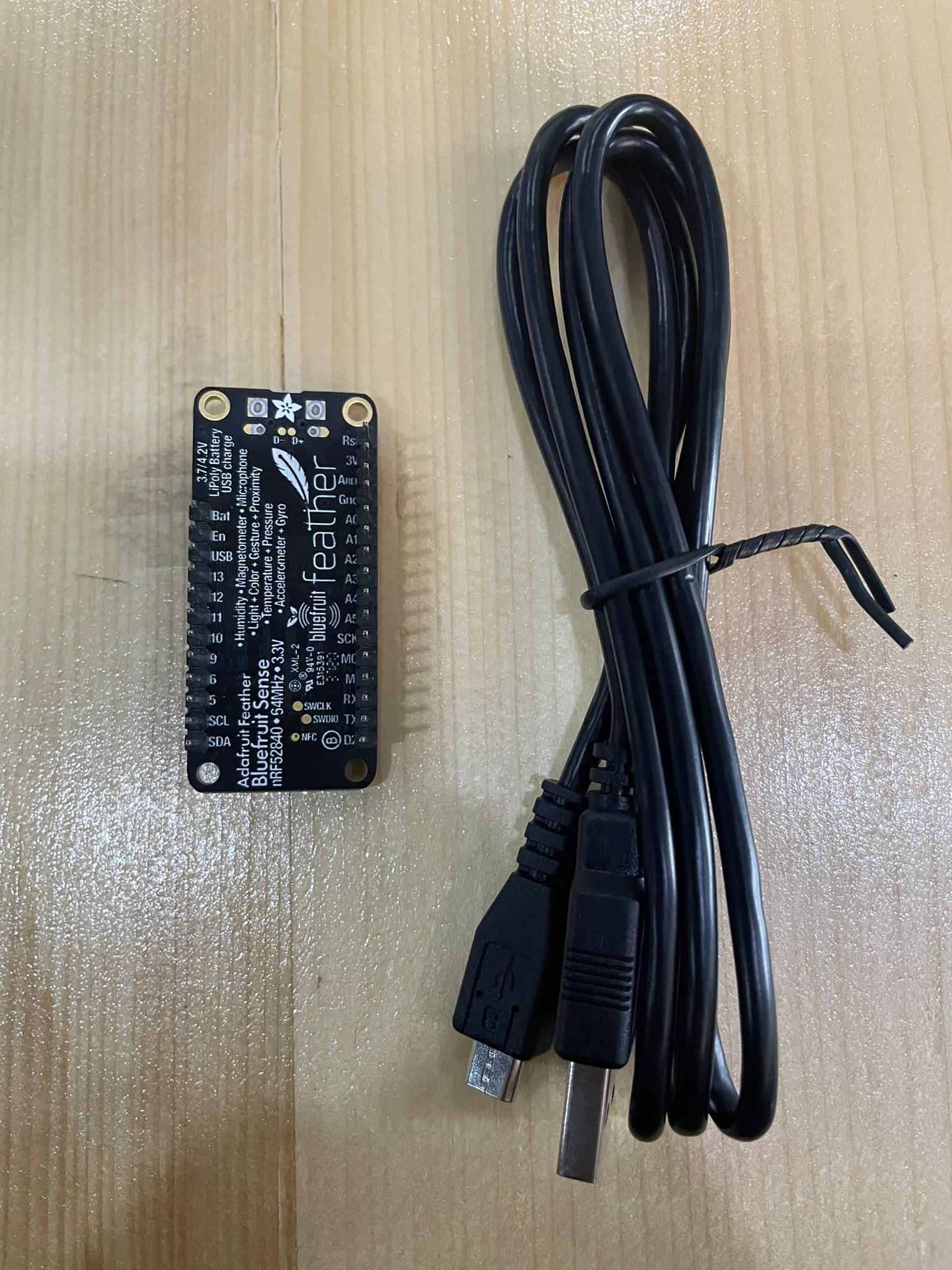
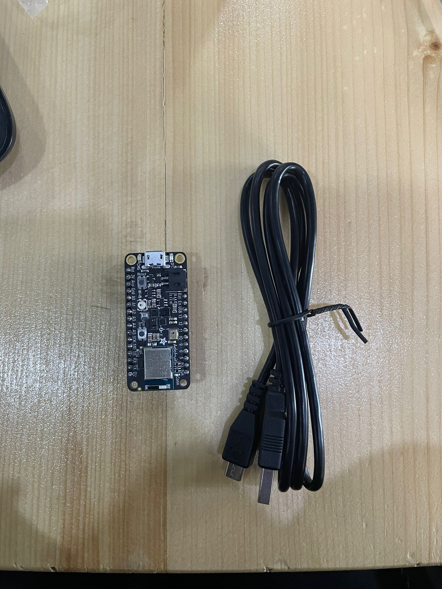 my microcontroller it Adafruit feather sense so I followed these steps in this link:steps link
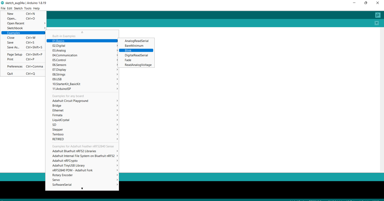
Blink Example
The task was The microcontroller was connected to the computer, and the following code was retrieved from file>examples>basics>blink. Both the low and high light times were modified to 1 second at first, but subsequently they were changed to different values. High indicates that the light will stay on for a set amount of time, while low indicates that it will turn off for another set amount of time.
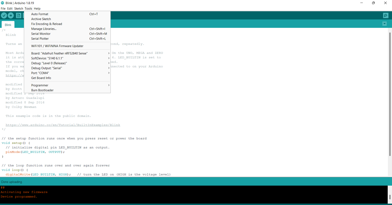
Upload and restart the microcontroller
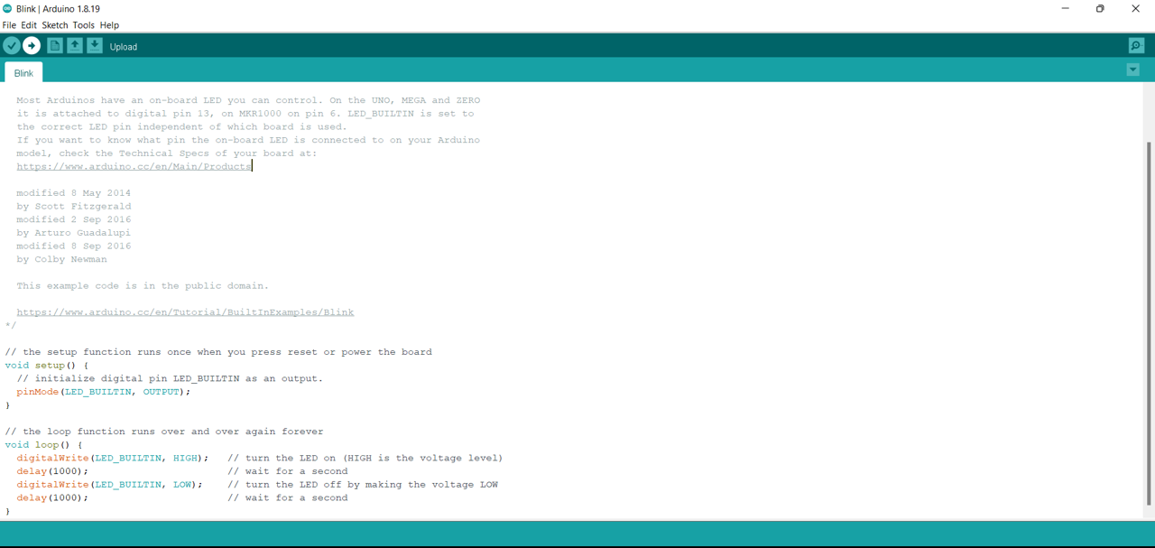
The code for blink example:
void setup() {
  // initialize digital pin LED_BUILTIN as an output.
  pinMode(LED_BUILTIN, OUTPUT);
}

// the loop function runs over and over again forever
void loop() {
  digitalWrite(LED_BUILTIN, HIGH);   // turn the LED on (HIGH is the voltage level)
  delay(1000);                       // wait for a second
  digitalWrite(LED_BUILTIN, LOW);    // turn the LED off by making the voltage LOW
  delay(1000);                       // wait for a second
Note: high mean on and low mean off.
Easy Level
blink led but have i blink delay periods be randomized values between 1 second and 5 seconds.
The code for easy level:
// C++ code
//
void setup()
{
  pinMode(LED_BUILTIN, OUTPUT);
}

void loop()
{
  digitalWrite(LED_BUILTIN, HIGH);
  delay(1000 * random(1, 5 + 1)); // Wait for 1000 * random(1, 5 + 1) millisecond(s)
  digitalWrite(LED_BUILTIN, LOW);
  delay(1000 * random(1, 5 + 1)); // Wait for 1000 * random(1, 5 + 1) millisecond(s)
}
Medium Level
pre code your microcontroller to send a Morse code 1 word message and challenge a friend, family member, your colleagues or your instructor to figure it out. dot = 0.5 second light on. dash=1 second light on. gap between dots and dashes=0.5 second light off. gap between letters=2 second light off.
The code for Medium level :
void setup() {
  // put your setup code here, to run once:
 pinMode(LED_BUILTIN, OUTPUT);

}

void loop() {
  // put your main code here, to run repeatedly:
digitalWrite(LED_BUILTIN, HIGH);
delay (500);
digitalWrite(LED_BUILTIN, LOW);
delay (2000);
digitalWrite(LED_BUILTIN, HIGH);
delay (1000);
digitalWrite(LED_BUILTIN, LOW);
delay (500);
digitalWrite(LED_BUILTIN, HIGH);
delay (500);
digitalWrite(LED_BUILTIN, LOW);
delay (2000);
digitalWrite(LED_BUILTIN, HIGH);
delay (1000);
digitalWrite(LED_BUILTIN, LOW);
delay (500);
digitalWrite(LED_BUILTIN, HIGH);
delay (500);
digitalWrite(LED_BUILTIN, LOW);
delay (500);
digitalWrite(LED_BUILTIN, HIGH);
delay (500);
}
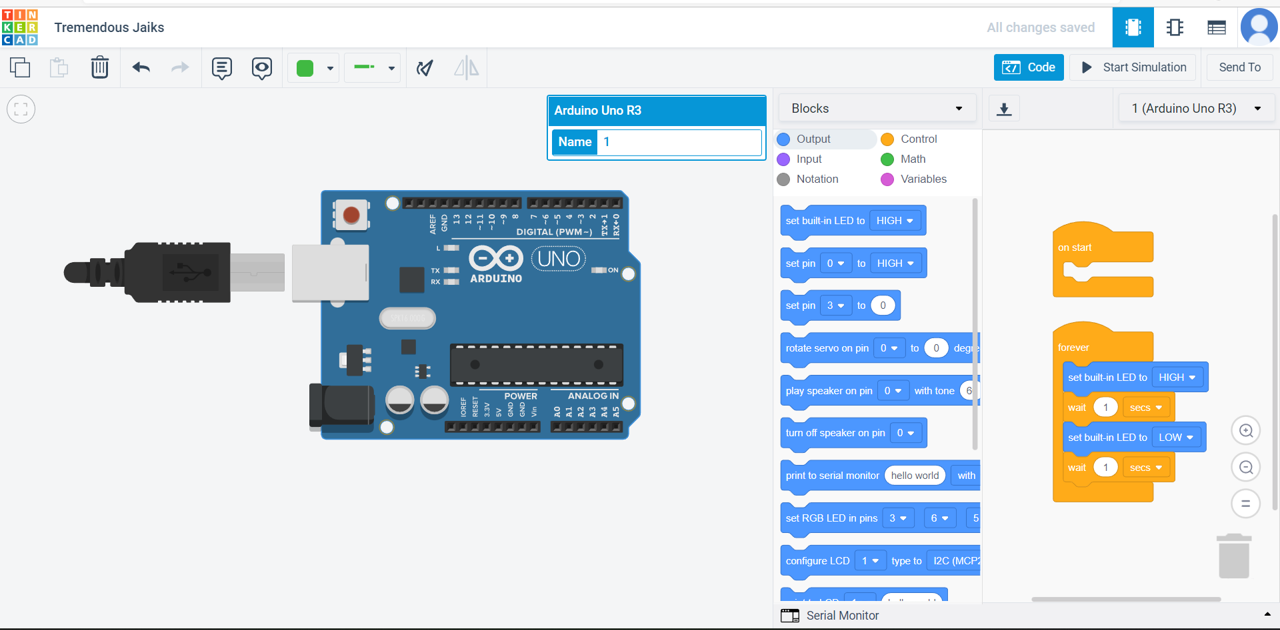
TinkerCAD
TinkerCAD is really quite helpful as a beginner-friendly circuit stimulation for microcontrollers in addition to 3D creations.
1.On the left side click circuits > create new circuit.
2.Drag Arduino Uno R3.
3.On right side > code .(When the ready-made code appears, you can begin stimulating right away.)
4.Morsecode is presented, and I’ll utilize it to create circuits in TinkerCAD.By using morse code
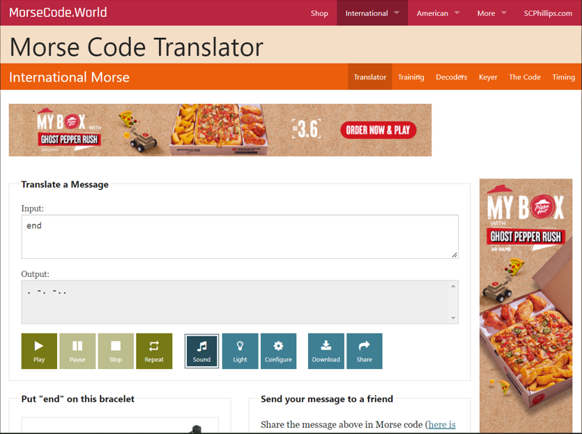
5.High=dash low=. dot = 0.5 sec dash = 1 sec gap between dot and dash = 0.5 sec (off) gap between letter = 2 sec off
6.My code in TinkerCAD The world:End , morsecode :. -. -..
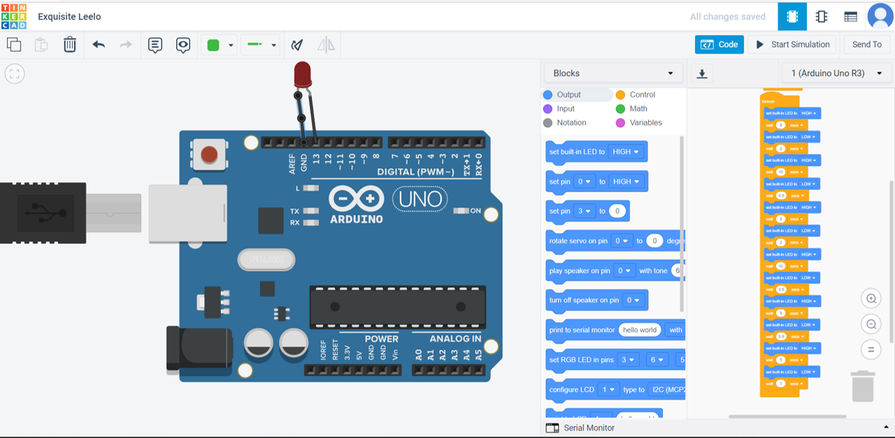
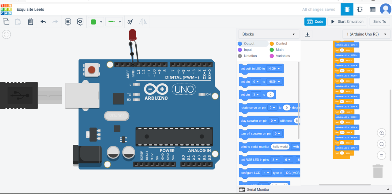
7.start simulation .
NOTE: the like from send to on the right side > invite people > copy the link.
My Opinion
A completely different week in Fab Lab. I enjoyed working and learned something new and different. I enjoyed working on Morse code the most.