7. Input & Output device
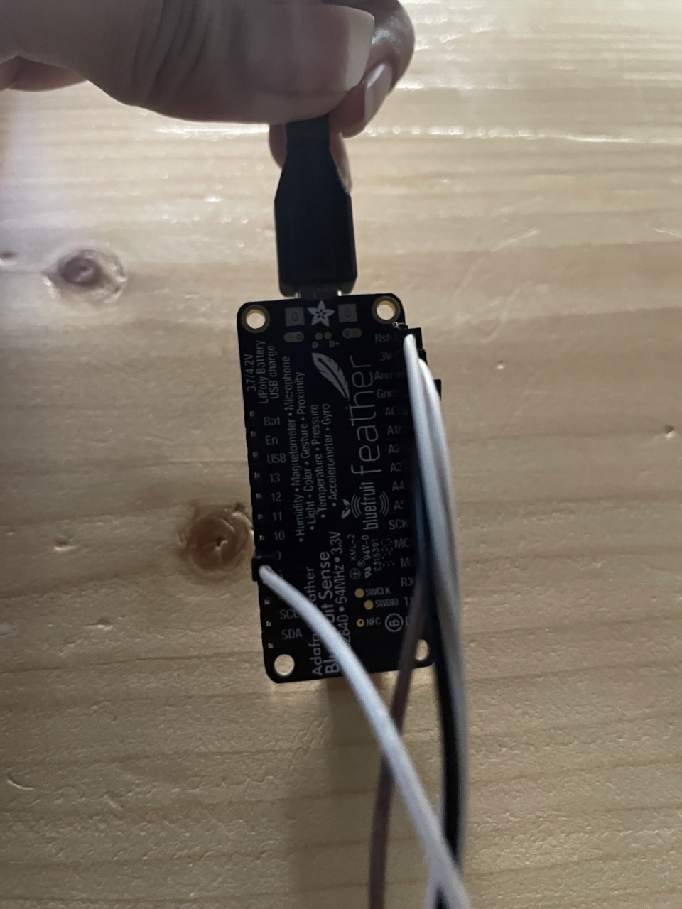
I worked this week working on input and output devices that were linked to an Arduino nano and programmed using the Arduino IDE software.
Input vs Output
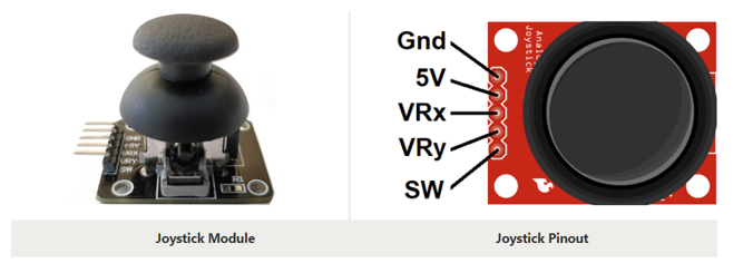
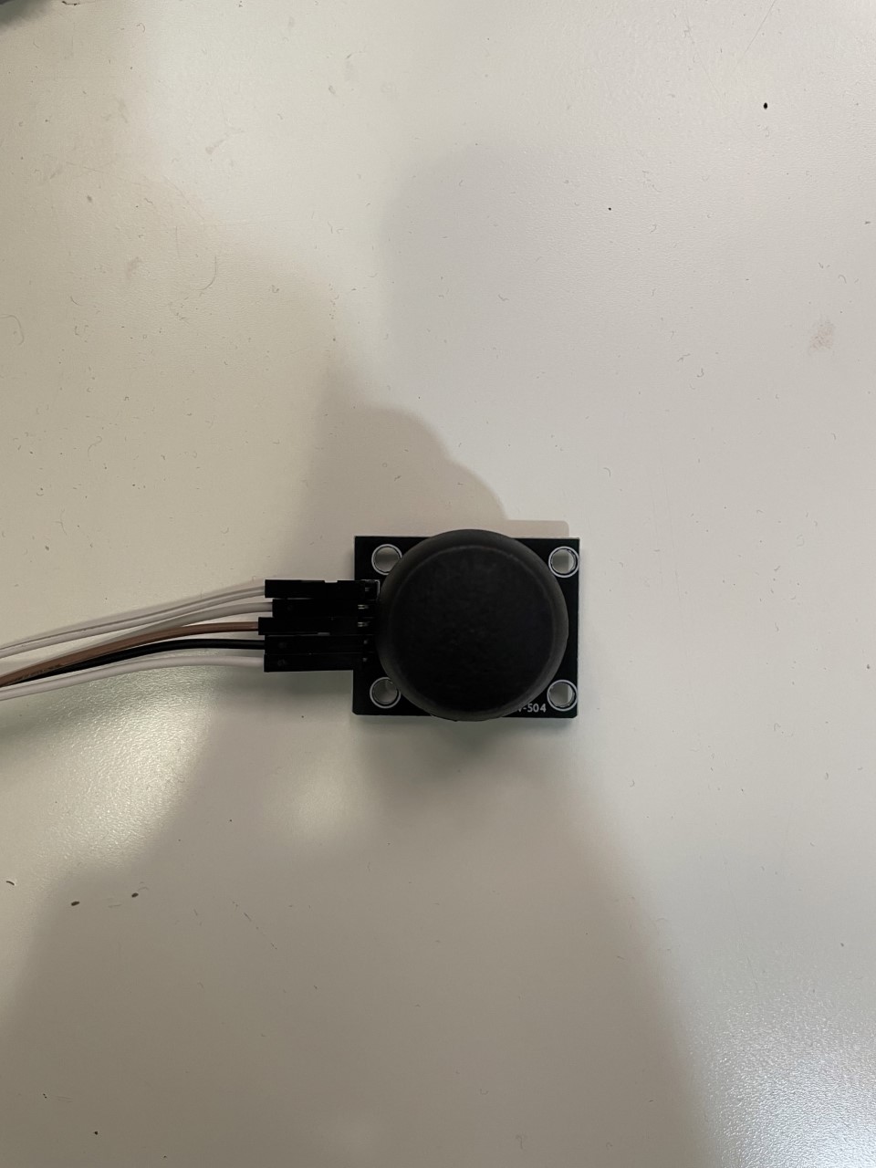
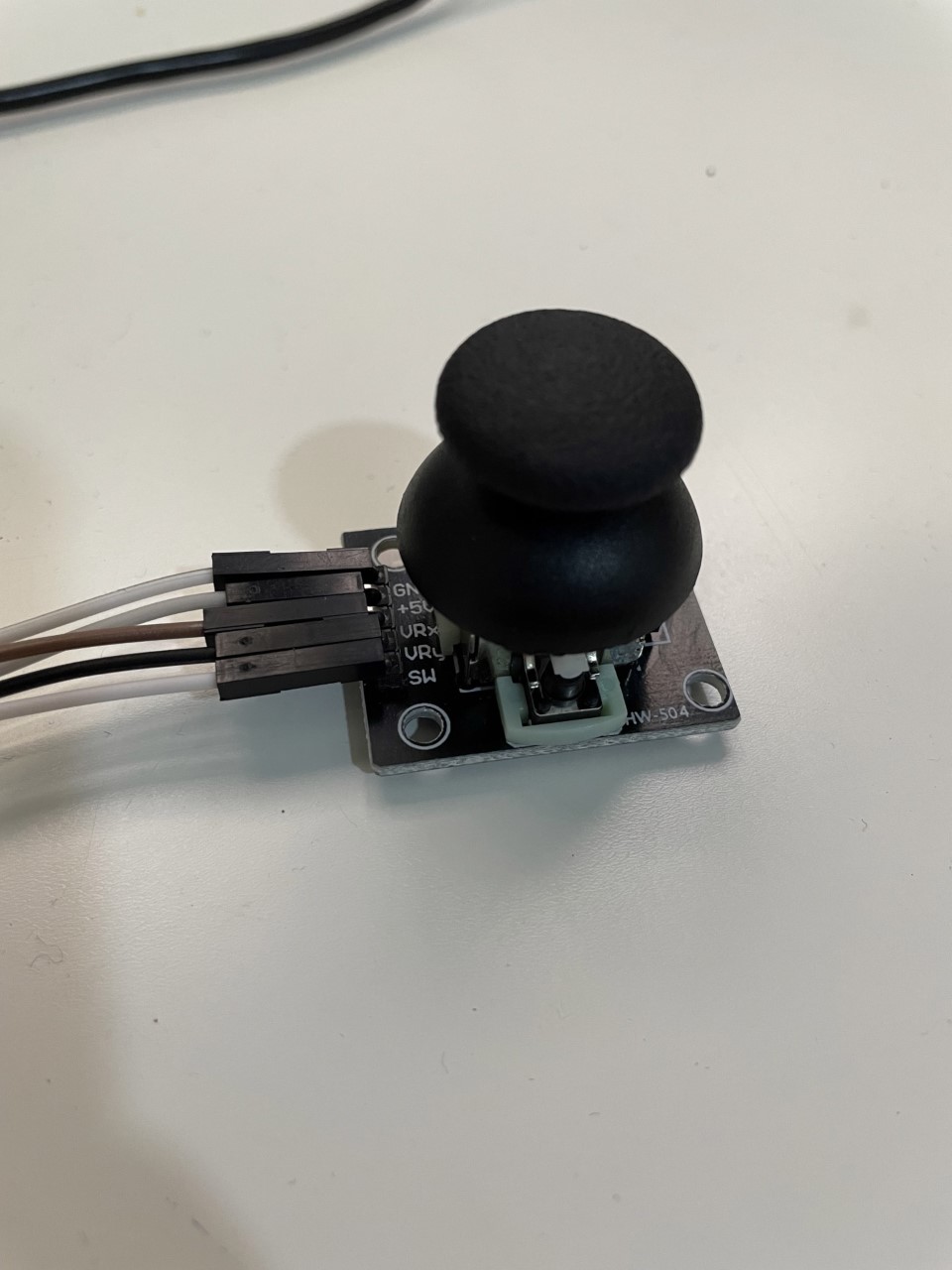
An output device is something you connect to a computer that has information sent to it, my out put is buzzer. An input device is something you connect to a computer that sends information into the computer,my input is joystick(hw-504) as show in the figures below.
Types of Electricity
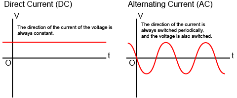
There are two types of electricity: direct current and alternating current. There are two methods of electric current. These are direct current (DC) and alternating current (AC). Direct current is a method in which electricity always flows in a certain direction, as compared to the flow of a river. It refers to the flow of electricity obtained from batteries, batteries, solar cells, etc. On the other hand, alternating current (AC) is a method in which the positive and negative sides are constantly switched periodically and the direction of the flow of electricity changes accordingly. This is the flow of electricity obtained from a generator or outlet. The electricity produced at power plants and sent to homes is also transmitted as alternating current. The diagram below shows the flow of DC and AC electricity.
In direct current, the voltage is always constant, and the electricity flows in a certain direction. In contrast, in alternating current, the voltage periodically changes from positive to negative and from negative to positive, and the direction of the current also periodically changes accordingly. In direct current, the voltage is always constant, and the electricity flows in a certain direction. In contrast, in alternating current, the voltage periodically changes from positive to negative and from negative to positive, and the direction of the current also periodically changes accordingly.
Input
-
Digital and analog inputs are the two categories into which inputs may be divided. There are 14 digital input ports and 8 analog input ports (numbered 0 to 7) on the Arduino nano microcontroller (from 2 to 13). The Arduino nano board measures voltages by default between 0 and 5 volts.
-
joystick(hw-504) The style joystick is a thumb operated device, that when put to creative use, offers a convenient way of getting operator input. Its fundamentally consists of two potentiometers and a push button switch. The two potentiometers indicate which direction the potentiometer is being pushed.The switch sends a low (or ground) when the joy stick knob is pressed.
1.Connect between microcontroller and input device by using jumper wires.
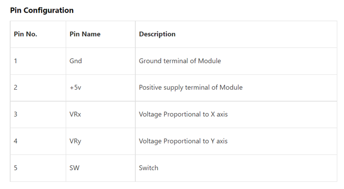
GND – Connect to ground line (GND).
+5V - Connect to 3V.
SW - Connect to 6.
VRy - Connect to A1.
VRx - Connect to A0.
Input Code
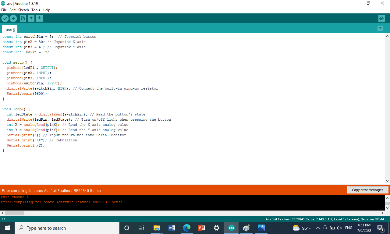
2.Enter the code .
const int switchPin = 9;  // Joystick button
const int pinX = A0; // Joystick X axis
const int pinY = A1; // Joystick Y axis
const int ledPin = 13;
 #include<SPI.h>
void setup() {
  pinMode(ledPin, OUTPUT);
  pinMode(pinX, INPUT);
  pinMode(pinY, INPUT);
  pinMode(switchPin, INPUT);
  digitalWrite(switchPin, HIGH); // Connect the built-in wind-up resistor
  Serial.begin(9600);
}

void loop() {
  int ledState = digitalRead(switchPin); // Read the button's state
  digitalWrite(ledPin, ledState); // Turn on/off light when pressing the button
  int X = analogRead(pinX); // Read the X axis analog value
  int Y = analogRead(pinY); // Read the Y axis analog value
  Serial.print(X); // Input the values into Serial Monitor
  Serial.print("\t"); // Tabulation
  Serial.println(Y);
}
#include<SPI.h>
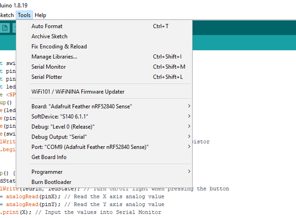
3.Upload and open the Serial Monitor from tool .
Input Video
Output
-
An output device is any piece of computer hardware equipment which converts information into human-readable form.
-
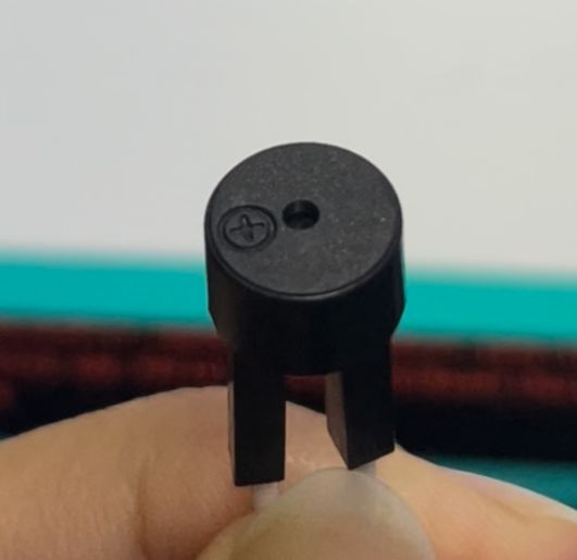
My output is buzzer.An arduino buzzer is also called a piezo buzzer. It is basically a tiny speaker that you can connect directly to an Arduino. You can make it sound a tone at a frequency you set. The buzzer produces sound based on reverse of the piezoelectric effect.Buzzers are used for making beeps, alarms and tones. They can be found in alarm devices, computers, timers and confirmation of user input such as a mouse click or keystroke. Buzzers are light weight, simple construction, and low cost.
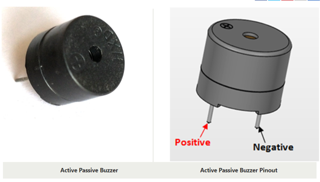
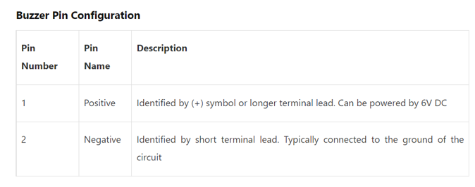
1.Contact microcontroller with output device by using two female wires (jumper wires).
3v to positive 11 to negative
Output Code
2.Enter the code > Upload .
const int buzzer=11;
// the setup function runs once when you press reset or power the board
void setup() {
  // initialize digital pin LED_BUILTIN as an output.
  pinMode(buzzer, OUTPUT);
}

// the loop function runs over and over again forever
void loop() {
  digitalWrite(buzzer, HIGH);   // turn the LED on (HIGH is the voltage level)
  delay(1000);                       // wait for a second
  digitalWrite(buzzer, LOW);    // turn the LED off by making the voltage LOW
  delay(1000);                       // wait for a second
}
Output Video
My Opinion
It wasn’t easy. It takes a lot of understanding and patience.