6. Embedded programming
This week was the first week since the beginning of the course that we worked with programming. Since it is divided into two weeks, only the basics were taught to us at this point. We worked with a couple of different microcontrollers and two different programming programs.
Group work
For this week’s group work, we were divided into pairs. Each pair was given a microcontroller and asked to research about its specifications. We then added all the information into one table to be able to compare between them.
The table can be viewed here.
What is Embedded programming?
Embedded programming is a method of programming that is used to control small, specialized computer systems, such as those found in appliances, vehicles, and industrial equipment. These systems, known as embedded systems, typically use microcontrollers or microprocessors to execute the code, and are designed to perform specific tasks. Embedded programming allows for the creation of customized, low-power, and low-cost systems that can be integrated into a wide range of products. The main advantages of embedded programming include the ability to create highly specialized systems, low power consumption, and low cost. However, embedded programming can also be more difficult and time-consuming than programming for larger systems, and can require specialized knowledge and tools. Additionally, embedded systems may have limited resources and processing power compared to larger systems, which can make it more challenging to implement certain features or functionality.
Having said that, what is a microcontroller and why is it significant?
A microcontroller is a small, low-power computer-on-a-chip that is designed to control a specific set of functions in an embedded system. It typically includes a microprocessor, memory, and peripheral interfaces all integrated into a single chip. Microcontrollers are used in a wide range of applications, including appliances, vehicles, industrial equipment, and consumer electronics.
Microcontrollers are significant for a number of reasons. They are small, low-power, and relatively inexpensive, which makes them well-suited for a wide range of embedded systems applications. They can be used to control a variety of functions, such as reading sensor data, controlling actuators, and communicating with other devices. This allows them to be integrated into a wide range of products, from appliances and vehicles to industrial equipment and consumer electronics.
Additionally, microcontrollers have the ability to perform specific tasks with high precision and repeatability, which is essential in many industrial and commercial applications. They can be programmed to perform complex tasks in a very efficient way and also consume low power. This makes them ideal for use in portable devices, such as smartphones and laptops, and in devices that must operate for long periods on batteries or other limited power sources.
Microcontrollers are also a key component of IoT (Internet of Things) devices, which are becoming increasingly prevalent in homes, businesses, and industries. They allow these devices to collect, process, and transmit data, enabling greater automation, control, and monitoring of systems and devices. Overall, microcontrollers play a crucial role in the design and development of embedded systems and IoT devices and also help to bring cost-effectiveness and efficiency.
There are several parts in a microcontroller that allow it to work efficiently, which are explained and shown in the table below.
| Part | Description |
|---|---|
| Processor | The central part of the microcontroller that executes instructions and controls its operation. |
| Memory | The storage on the microcontroller, divided into ROM (program code) and RAM (data storage). |
| Input/Output (I/O) interfaces | Ports on the microcontroller that allow it to interact with the outside world. Can be digital or analog. |
| Pins | Metal connectors on the microcontroller that provide access to the I/O interfaces. |
| Sensors | Devices that detect changes in the physical world and provide input to the microcontroller. |
| Buttons | Switches used to provide input to the microcontroller, often used for user interfaces. |
| Communication interfaces | Ports on the microcontroller that allow it to communicate with other devices, such as a computer or another microcontroller. Examples include UART, SPI, and I2C. |
The microcontrollers we used this week were the adafruit feather sense and the adafruit feather express
Adafruit feather sense
Since I was working with the adafruit feather sense microcontroller specifically, I had to read its datasheet, which is linked here.
The Adafruit Feather nRF52840 Sense is a compact development board that uses the nRF52840 chip, which is capable of running at 64MHz and supports Bluetooth 5, Bluetooth Low Energy, and NFC.
It is designed for use in a variety of IoT applications, including wearables, smart home devices, and environmental monitoring systems. It is compatible with the Arduino IDE, CircuitPython, and the Nordic nRF5 SDK, making it easy to get started with development.
Sensors
The Adafruit Feather nRF52840 Sense board comes with a variety of sensors, including:
-
Temperature and humidity sensor: This sensor measures both temperature and humidity and is useful for monitoring environmental conditions.
-
Light sensor: The light sensor on the board measures ambient light levels and is useful for applications where you need to detect changes in lighting conditions.
-
Accelerometer: The accelerometer measures changes in motion and is useful for applications such as tracking movement or detecting changes in orientation.
-
Magnetometer: The magnetometer measures changes in magnetic fields and is useful for applications such as detecting the position of a magnetic object.
-
Gyroscope: The gyroscope measures changes in orientation and is useful for applications such as stabilizing cameras or tracking movement.
Pins
The Adafruit Feather nRF52840 Sense board has a range of pins that can be used for various purposes, including:
-
Digital pins: These pins can be used for general-purpose digital input/output (I/O) functions.
-
Analog pins: These pins can be used for analog input functions.
-
PWM pins: These pins can be used for pulse-width modulation (PWM) functions, which are often used for controlling motors or LED brightness.
-
I2C and SPI pins: These pins can be used for communicating with other devices using the I2C or SPI protocols.
Other Features
In addition to the sensors and pins, the Adafruit Feather nRF52840 Sense board also has other features, including:
-
Built-in antenna: The board has a built-in antenna, which eliminates the need for an external antenna.
-
Flash memory and RAM: The board has 1MB of flash memory and 256KB of RAM, which can be used for storing code and data.
-
Micro USB port: The board has a micro USB port, which can be used for charging the board or programming it.
-
JST battery connector: The board has a JST battery connector, which can be used for powering the board using a battery.
Overall, the Adafruit Feather nRF52840 Sense is a powerful and versatile development board that offers a range of features and sensors, making it ideal for a wide range of IoT applications. It has a wide range of sensors, pins, and other features, which make it a versatile and powerful development board for a variety of IoT applications.
Programming platforms
In this week, we worked with two main programs: Arduino IDE and Mu Editor. For each program, we had a set of challenges we needed to perform.
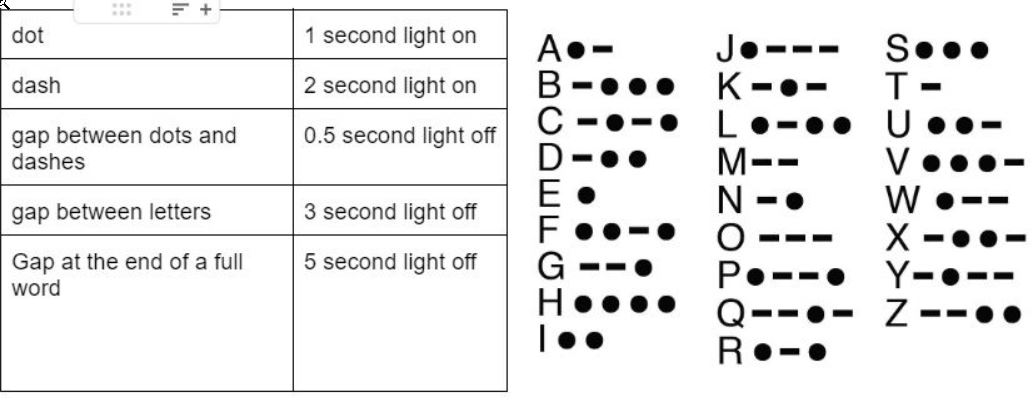
The first challenge was the blink challenge, which entailed working on the blink effect in the microcontroller, to allow it to randomly blink in random intervals between 1 to 5 seconds.
The second challenge was creating a morse code using the blink effect too, with each letter being represented by a specific number of blinks in a specific time for each.
Arduino IDE
The Arduino IDE (Integrated Development Environment) is a software application that allows users to write and upload code to an Arduino board. It is a cross-platform application, available for Windows, Mac, and Linux, and provides a simple and user-friendly interface for programming and interacting with Arduino boards. The IDE includes a text editor for writing code, a built-in serial monitor for debugging, and the ability to upload code to the board using a USB cable. It also includes a library manager for downloading and installing additional libraries and sample code to expand the functionality of the Arduino board. The Arduino IDE supports many programming languages such as C++, and it is widely used by hobbyists, students, and professionals to create a variety of interactive projects and devices.
The program can be downloaded here.
Linking Adafruit with Arduino IDE
Since Adafruit boards are not pre-installed in the arduino prgoram, I had to first install it before proceeding with anything else.
Arduino IDE challenges
Challenge 1: Blink coding
For this challenge, I used the built-in example in the arduino program. ALl information about the code can be found here.
I then fixed the code to make the blinks random instead of fixed. The code can be seen below.
void setup() {
  // initialize digital pin LED_BUILTIN as an output.
  pinMode(LED_BUILTIN, OUTPUT);
}

// the loop function runs over and over again forever
void loop() {
  digitalWrite(LED_BUILTIN, HIGH);  // turn the LED on (HIGH is the voltage level)
  delay(random(1000,5000));                      // wait for a random value between 1-5 seconds
  digitalWrite(LED_BUILTIN, LOW);   // turn the LED off by making the voltage LOW
  delay(random(1000,5000));                      // wait for a random value between 1-5 seconds
}
Challenge 2: Morse code blink
For this challenge, I used the same previous example, but extended it more and added extra codes in order for it to spell “Believe” in morse code.
Following the table attached above, the code looked as follows.
void setup() {
  // initialize digital pin LED_BUILTIN as an output.
  pinMode(LED_BUILTIN, OUTPUT);
}

// the loop function runs over and over again forever
void loop() {
//B
   digitalWrite(LED_BUILTIN, HIGH);  // turn the LED on (HIGH is the voltage level)
  delay(2000);                      // dash
  digitalWrite(LED_BUILTIN, LOW);   // turn the LED off by making the voltage LOW
  delay(500);                      // gap
   digitalWrite(LED_BUILTIN, HIGH);  // turn the LED on (HIGH is the voltage level)
  delay(1000);                      // dot
  digitalWrite(LED_BUILTIN, LOW);   // turn the LED off by making the voltage LOW
  delay(500);                      // gap
   digitalWrite(LED_BUILTIN, HIGH);  // turn the LED on (HIGH is the voltage level)
  delay(1000);                      // dot
  digitalWrite(LED_BUILTIN, LOW);   // turn the LED off by making the voltage LOW
  delay(500);                      // gap
   digitalWrite(LED_BUILTIN, HIGH);  // turn the LED on (HIGH is the voltage level)
  delay(1000);                      // dot
  digitalWrite(LED_BUILTIN, LOW);   // turn the LED off by making the voltage LOW
  delay(3000);                      // gap between letters
//E
   digitalWrite(LED_BUILTIN, HIGH);  // turn the LED on (HIGH is the voltage level)
  delay(1000);                      // dot
  digitalWrite(LED_BUILTIN, LOW);   // turn the LED off by making the voltage LOW
  delay(3000);                      // gap between letters
//l
   digitalWrite(LED_BUILTIN, HIGH);  // turn the LED on (HIGH is the voltage level)
  delay(1000);                      // dot
  digitalWrite(LED_BUILTIN, LOW);   // turn the LED off by making the voltage LOW
  delay(500);                      // gap
   digitalWrite(LED_BUILTIN, HIGH);  // turn the LED on (HIGH is the voltage level)
  delay(2000);                      // dash
  digitalWrite(LED_BUILTIN, LOW);   // turn the LED off by making the voltage LOW
  delay(500);                      // gap
    digitalWrite(LED_BUILTIN, HIGH);  // turn the LED on (HIGH is the voltage level)
  delay(1000);                      // dot
  digitalWrite(LED_BUILTIN, LOW);   // turn the LED off by making the voltage LOW
  delay(500);                      // gap
    digitalWrite(LED_BUILTIN, HIGH);  // turn the LED on (HIGH is the voltage level)
  delay(1000);                      // dot
  digitalWrite(LED_BUILTIN, LOW);   // turn the LED off by making the voltage LOW
  delay(3000);                      // gap between letters
//I
   digitalWrite(LED_BUILTIN, HIGH);  // turn the LED on (HIGH is the voltage level)
  delay(1000);                      // dot
  digitalWrite(LED_BUILTIN, LOW);   // turn the LED off by making the voltage LOW
  delay(500);                      // gap
    digitalWrite(LED_BUILTIN, HIGH);  // turn the LED on (HIGH is the voltage level)
  delay(1000);                      // dot
  digitalWrite(LED_BUILTIN, LOW);   // turn the LED off by making the voltage LOW
  delay(3000);                      // gap between letters
//E
   digitalWrite(LED_BUILTIN, HIGH);  // turn the LED on (HIGH is the voltage level)
  delay(1000);                      // dot
  digitalWrite(LED_BUILTIN, LOW);   // turn the LED off by making the voltage LOW
  delay(3000);                      // gap between letters
//V
   digitalWrite(LED_BUILTIN, HIGH);  // turn the LED on (HIGH is the voltage level)
  delay(1000);                      // dot
  digitalWrite(LED_BUILTIN, LOW);   // turn the LED off by making the voltage LOW
  delay(500);                      // gap
   digitalWrite(LED_BUILTIN, HIGH);  // turn the LED on (HIGH is the voltage level)
  delay(1000);                      // dot
  digitalWrite(LED_BUILTIN, LOW);   // turn the LED off by making the voltage LOW
  delay(500);                      // gap
    digitalWrite(LED_BUILTIN, HIGH);  // turn the LED on (HIGH is the voltage level)
  delay(1000);                      // dot
  digitalWrite(LED_BUILTIN, LOW);   // turn the LED off by making the voltage LOW
  delay(500);                      // gap
    digitalWrite(LED_BUILTIN, HIGH);  // turn the LED on (HIGH is the voltage level)
  delay(2000);                      // dash
  digitalWrite(LED_BUILTIN, LOW);   // turn the LED off by making the voltage LOW
  delay(3000);                      // gap between letters
//E
   digitalWrite(LED_BUILTIN, HIGH);  // turn the LED on (HIGH is the voltage level)
  delay(1000);                      // dot
  digitalWrite(LED_BUILTIN, LOW);   // turn the LED off by making the voltage LOW
  delay(5000);                      // gap at the end of a full word
}
Mu Editor
The mu editor is a simple code editor for beginner programmers. It is specifically designed to be used with the MicroPython programming language, which is a version of Python that is optimized to run on microcontrollers and other small devices. The mu editor provides a simple, easy-to-use interface for editing and running MicroPython code, and it also includes a built-in Python interpreter and a file explorer for managing files on the device.
When using Mu editor, there are three main things we need to download, which can be accessed from the links below:
After downloading all of these, there are some steps we need to follow before being able to use Mu editor to program the microcontroller.
First, we need to connect the microcontroller to the monitor, and open the file in (this pc). Then, we drag the second download (adafruit microcontroller for CircuitPython) into that folder. This will change the microcontroller name to CIRCUITPY.
After that, we check the (lib) folder in the microcontroller. If it is empty, we drag all the circuitpyhton libraries we downloaded there, so we can use them in the programming.
When that is done, our microcontroller is ready to be programmed using Mu editor, and the CircuitPyhton language.
For this program, I did the second challenge, which was the morse code, directly.
Challenge 2: Morse code blink
Before starting, I got an example from this link. I then rearranged the code to spell “Purple” in morse code, based on the table above.
"""CircuitPython Blink Example - the CircuitPython 'Hello, World!'"""
import time
import board
import digitalio

led = digitalio.DigitalInOut(board.LED)
led.direction = digitalio.Direction.OUTPUT

while True:
    #P
    led.value = True
    time.sleep(1)
    led.value = False
    time.sleep(0.5)
    led.value = True
    time.sleep(2)
    led.value = False
    time.sleep(0.5)
    led.value = True
    time.sleep(2)
    led.value = False
    time.sleep(0.5)
    led.value = True
    time.sleep(1)
    led.value = False
    time.sleep(3)

    #U
    led.value = True
    time.sleep(1)
    led.value = False
    time.sleep(0.5)
    led.value = True
    time.sleep(1)
    led.value = False
    time.sleep(0.5)
    led.value = True
    time.sleep(2)
    led.value = False
    time.sleep(3)

    #R
    led.value = True
    time.sleep(1)
    led.value = False
    time.sleep(0.5)
    led.value = True
    time.sleep(2)
    led.value = False
    time.sleep(0.5)
    led.value = True
    time.sleep(1)
    led.value = False
    time.sleep(3)

    #P
    led.value = True
    time.sleep(1)
    led.value = False
    time.sleep(0.5)
    led.value = True
    time.sleep(2)
    led.value = False
    time.sleep(0.5)
    led.value = True
    time.sleep(2)
    led.value = False
    time.sleep(0.5)
    led.value = True
    time.sleep(1)
    led.value = False
    time.sleep(3)

    #L
    led.value = True
    time.sleep(1)
    led.value = False
    time.sleep(0.5)
    led.value = True
    time.sleep(2)
    led.value = False
    time.sleep(0.5)
    led.value = True
    time.sleep(1)
    led.value = False
    time.sleep(0.5)
    led.value = True
    time.sleep(1)
    led.value = False
    time.sleep(3)

    #E
    led.value = True
    time.sleep(1)
    led.value = False
    time.sleep(5)
Videos
This first video shows the first challenge, which is the random blinking.
This second video shows the second challenge, morse code blinking.