8. Inputs and Outputs
During this week, we talked more about programming, and how to use inputs and outputs in our devices. We experimented with several different ones, each based on what they would need for their final project.
What are inputs and outputs?
In programming, inputs and outputs are data that are passed into and out of a program, respectively.
Inputs are the data that a program takes as an input to perform some operation. For example, if you are writing a program to calculate the sum of two numbers, the two numbers would be the inputs to the program. Inputs can come from a variety of sources such as a file, keyboard, database, network or another program. Some examples are mentioned in the table below:
| Input | Description | Example |
|---|---|---|
| Keyboard Input | Data entered using the keyboard | User inputting their name into a form |
| Mouse Input | Data entered using the mouse | User clicking a button on a graphical user interface |
| File Input | Data read from a file | A program reading data from a text file |
| Network Input | Data received from a network connection | A web server receiving a request from a client |
| Command-line Input | Data entered as a command-line argument | A user providing a filename as an argument when running a program |
| API Input | Data received from an external API | A weather app receiving data from a weather API |
Outputs, on the other hand, are the results or data that a program generates after performing an operation using the inputs. Continuing the previous example, the output of a program that calculates the sum of two numbers would be the sum of those two numbers. Outputs can also be sent to various destinations such as a file, screen, database, network, or another program. Some examples are mentioned below:
| Output | Description | Example |
|---|---|---|
| Screen Output | Data displayed on the screen | A game displaying the score of the player |
| File Output | Data written to a file | A program saving its output to a text file |
| Network Output | Data sent over a network connection | A web server sending a response to a client |
| Printer Output | Data printed to a printer | A program printing a document |
| Audio Output | Sound played through speakers or headphones | A music player playing a song |
| API Output | Data sent to an external API | A program sending data to a payment gateway API |
In summary, inputs and outputs are two crucial concepts in programming that enable a program to interact with its environment, receive data, perform operations, and produce results.
Digital and analog pins
Analog and digital pins are two different types of input/output pins on a microcontroller or microprocessor.
Analog pins are used to read analog signals, which are continuous voltage signals that can take on any value within a range. Examples of analog signals include audio signals, temperature readings, and light levels. Analog pins typically have a range of 0 to 5 volts, and they can read signals with a resolution of up to 10 bits (1024 discrete values).
Digital pins, on the other hand, are used to read and write digital signals, which are discrete voltage signals that can only take on two values: high (typically represented by 5 volts) and low (typically represented by 0 volts). Examples of digital signals include binary data, switch states, and PWM signals. Digital pins can read and write signals with a resolution of 1 bit.
In summary, the main difference between analog and digital pins is that analog pins read continuous signals with a range of values, while digital pins read and write discrete signals with only two possible values.
Individual assignment
Within this week, I experimented with 3 different inputs and outputs, which are the RGB LED, SMD RGB, and the digital touch sensor.
Output 1: RGB LED
RGB LED output refers to the colors produced by a light-emitting diode (LED) that is capable of emitting red, green, and blue light. By controlling the intensity of each color, an RGB LED can produce a wide range of colors.
The output of an RGB LED is typically specified in terms of the intensity of each color component, which is typically expressed as a value between 0 and 255 for each color. This is known as the RGB color model, and it is used to represent colors on digital displays and other electronic devices.
For example, to produce a color that is a mixture of 50% red, 75% green, and 100% blue, the RGB values would be (128, 191, 255). By adjusting the intensity of each color component, an RGB LED can produce a wide range of colors, from pure white (255, 255, 255) to black (0, 0, 0) and everything in between.
Connections After learning about the device, I connected the wiring in the way it was done in the diagram below.
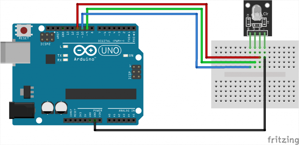
Then, I took this code from the internet and altered it with what i found suitable. The results can be seen in the video after the code.
const int redPin = 11;  // R petal on RGB LED module connected to digital pin 11
const int greenPin = 10;  // G petal on RGB LED module connected to digital pin 10
const int bluePin = 9;  // B petal on RGB LED module connected to digital pin 9
/**************************************************************************/
void setup()
{
  pinMode(redPin, OUTPUT); // sets the redPin to be an output
  pinMode(greenPin, OUTPUT); // sets the greenPin to be an output
  pinMode(bluePin, OUTPUT); // sets the bluePin to be an output
}
/***************************************************************************/
void loop()  // run over and over again
{
  // Basic colors:
  color(23, 81, 126);
  delay(1000); // delay for 1 second

}
/******************************************************/
void color (unsigned char red, unsigned char green, unsigned char blue)// the color generating function
{
  analogWrite(redPin, red);
  analogWrite(greenPin, green);
  analogWrite(bluePin, blue);
}
Output 2: SMD RGB
SMD RGB is a type of RGB LED that is designed to be mounted on a printed circuit board (PCB) using surface-mount technology (SMT). SMT components, including SMD RGB LEDs, are typically smaller and more compact than through-hole components, which makes them suitable for use in applications where space is limited.
SMD RGB LEDs typically come in a package that includes multiple LED dies, each of which emits a different color of light. By controlling the brightness of each LED die, SMD RGB LEDs can produce a wide range of colors.
The output of an SMD RGB LED is also specified in terms of the intensity of each color component, which is typically expressed as a value between 0 and 255 for each color. However, the exact specifications of an SMD RGB LED may vary depending on the manufacturer and the specific product. It is important to consult the datasheet for the particular SMD RGB LED that you are working with in order to understand its specific electrical and optical characteristics.
Connections After learning about the device, I connected the wiring in the way it was done in the diagram below.
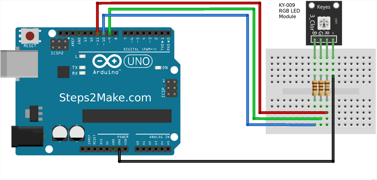
Then, I took this code from the internet and altered it with what i found suitable. The results can be seen in the video after the code.
#include <SPI.h>
const int redPin = 9;  // R petal on RGB LED module connected to digital pin 11
const int greenPin = 10;  // G petal on RGB LED module connected to digital pin 10
const int bluePin = 11;  // B petal on RGB LED module connected to digital pin 9
byte touch_sense = 5; // designate input pin

// These variables are for timing purposes
int kk = 1;int time_out = 1;
bool state_on = 0;
/**************************************************************************/
void setup()
{
  pinMode(redPin, OUTPUT); // sets the redPin to be an output
  pinMode(greenPin, OUTPUT); // sets the greenPin to be an output
  pinMode(bluePin, OUTPUT); // sets the bluePin to be an output
  Serial.begin(9600);
  // make the touch sensor pin an input:
  pinMode(touch_sense, INPUT);
}
/***************************************************************************/
void loop()  // run over and over again
{
 // delay for 1 second
  time_out++; // iterate
  int touch_state = digitalRead(touch_sense);
  Serial.print(touch_state);
  // if statement asking how many times it has been triggered:
  if (touch_state==1 and state_on == 0) {
    kk++;
    state_on = 1;
    color(236, 220, 175); // turn the RGB LED red
    delay(5000);
  } else if (state_on==1 and touch_state == 0) {
    state_on = 0;
    color(26, 163, 251); // turn the RGB LED red
    delay(50);
  }
}
/******************************************************/
void color (unsigned char red, unsigned char green, unsigned char blue)// the color generating function
{
  analogWrite(redPin, red);
  analogWrite(greenPin, green);
  analogWrite(bluePin, blue);
}
Input: Hall Effect Sensor
A Hall effect sensor is an electronic device that can detect the presence of a magnetic field. When a magnetic field is applied perpendicular to the sensor, it generates a voltage proportional to the strength of the field. This voltage can be used as an input signal for various electronic circuits.
Hall effect sensors are commonly used in industrial applications for detecting the position and speed of rotating equipment such as motors, gears, and wheels. They can also be used in electronic compasses, proximity sensors, and current sensors.
Hall effect sensors are available in different types, such as linear and digital, and can be used with various magnetic field strengths and sensitivities. They are also available in different package types, including surface mount and through-hole, making them versatile and easy to integrate into different electronic designs.
#include <SPI.h>


 void setup()
 {
  Serial.begin(9600);   // sensor buart rate
  pinMode(9,OUTPUT);   // LED connect D9 Pin
  pinMode(10,OUTPUT);
  pinMode(11,OUTPUT);
  pinMode(A0,INPUT);

 }
 void loop()
 {
  int s1=analogRead(A0); //Hall Effect Sensor Connect A0 pin
  Serial.println(s1);
  delay(500);
  if( s1 > 500 )
  {
    digitalWrite(9,HIGH); // LED ON
    digitalWrite(10,LOW); // LED ON
    Serial.println(" Magnet IS Detected ");
  }
  else if ( s1 < 500 )
  {
   digitalWrite(9,LOW);  // LED OFF
   digitalWrite(10,HIGH); // LED ON
   Serial.println(" Magnet IS not Detected ");
  }
 }