Final Project: Lenio Light
For my final project, I paired up with Sakeena Al-Haddad, one of my class mates in the Fab academy program. Within the two weeks we had to work on our final project, we finalized our idea and started the execution. In the following sections, I will explain the digital design and the programming steps we followed. The rest of the information, which includes the fabrication steps can be accessed from my classmate’s website, by following this link.
Digital Design
After thinking over the design of the lamp, we decided to proceed with one goal in mind: to make something that’s functional, yet beautiful and modern. We wanted this product to look good enough that people would be proud to display it at home, in bedroom, in offices, and so on.
In order to achieve that, we decided to go with a simple cubic shape, and then focus more on its finishing and perfecting it.
The assembly process is displayed in my colleague’s website, but I will explain the digital design process in the coming part.
The process
The main thing we wanted to focus on in the design is to use joints, to minimize the use of glue and screws, which is one thing we learned in the fab academy program and wanted to implement in our final project. After experimenting several times with acrylic, we found that the joints needed to have a clearance of 0.6mm. Therefore, the female joint was 0.6mm smaller than the male joint.
Having said that, our digital design stage was divided into two: the main body of the lamp, and the base. In the coming steps, I will explain the design of the body first, and then proceed to explain the design of the base.
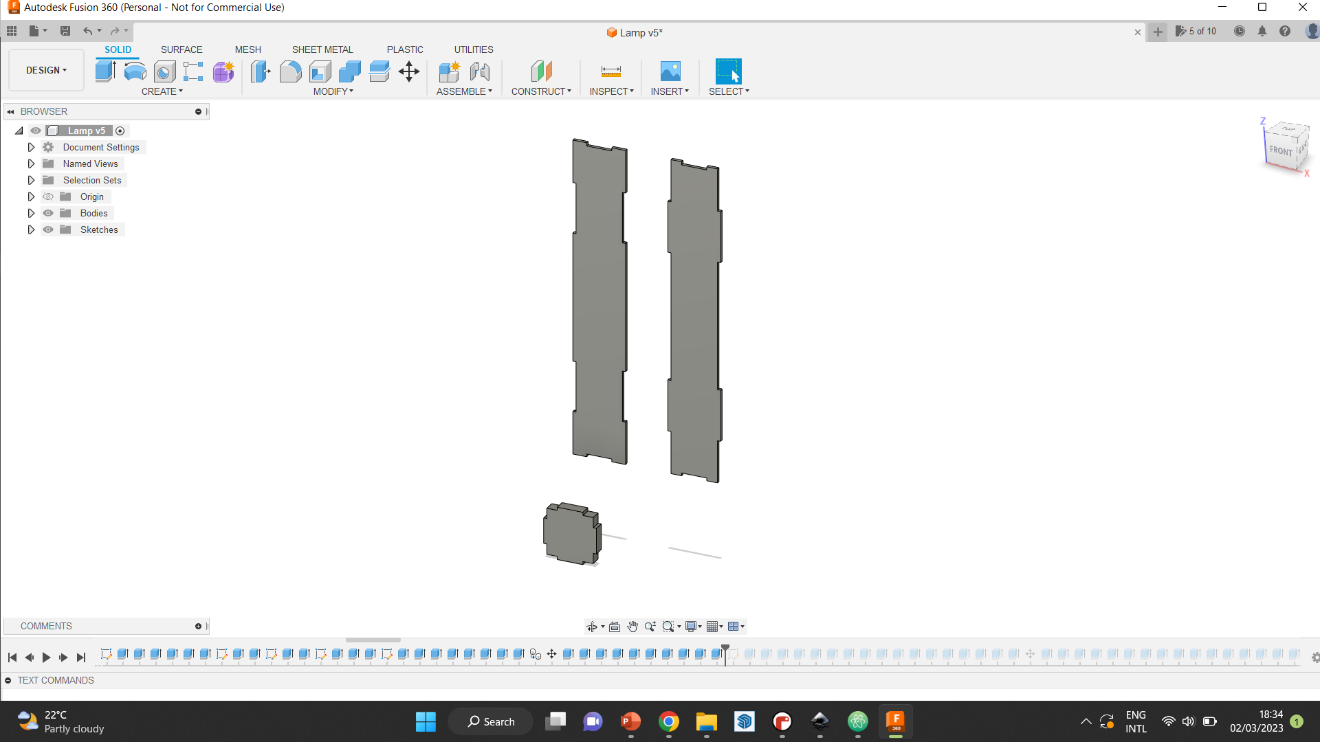
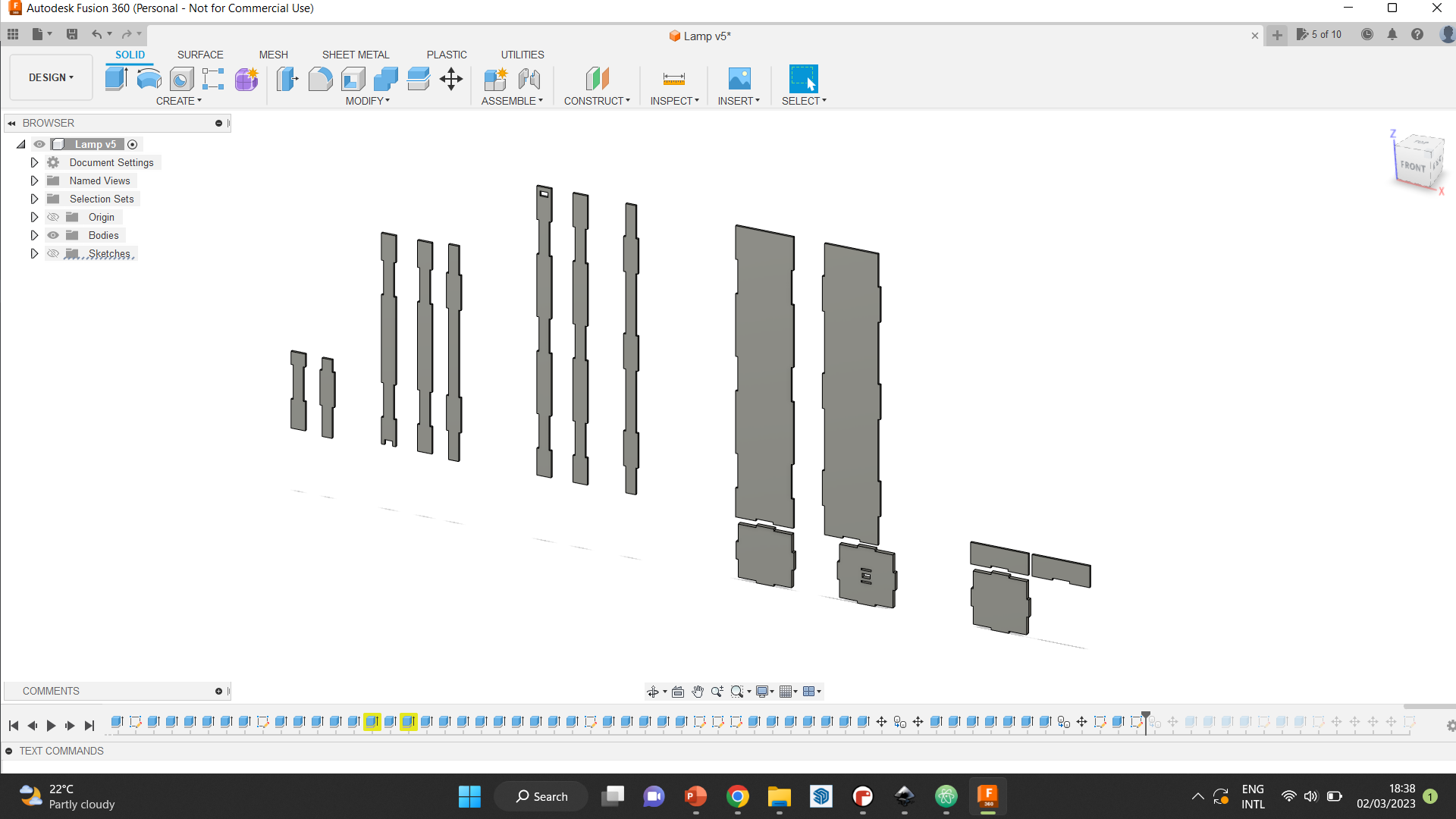
Step 1 was to create the main pieces that we wanted to use. In the beginning, we wanted to create a small lamp, for it to be easily portable, which is why these pieces were around 30cm in length, and 5cm in width.
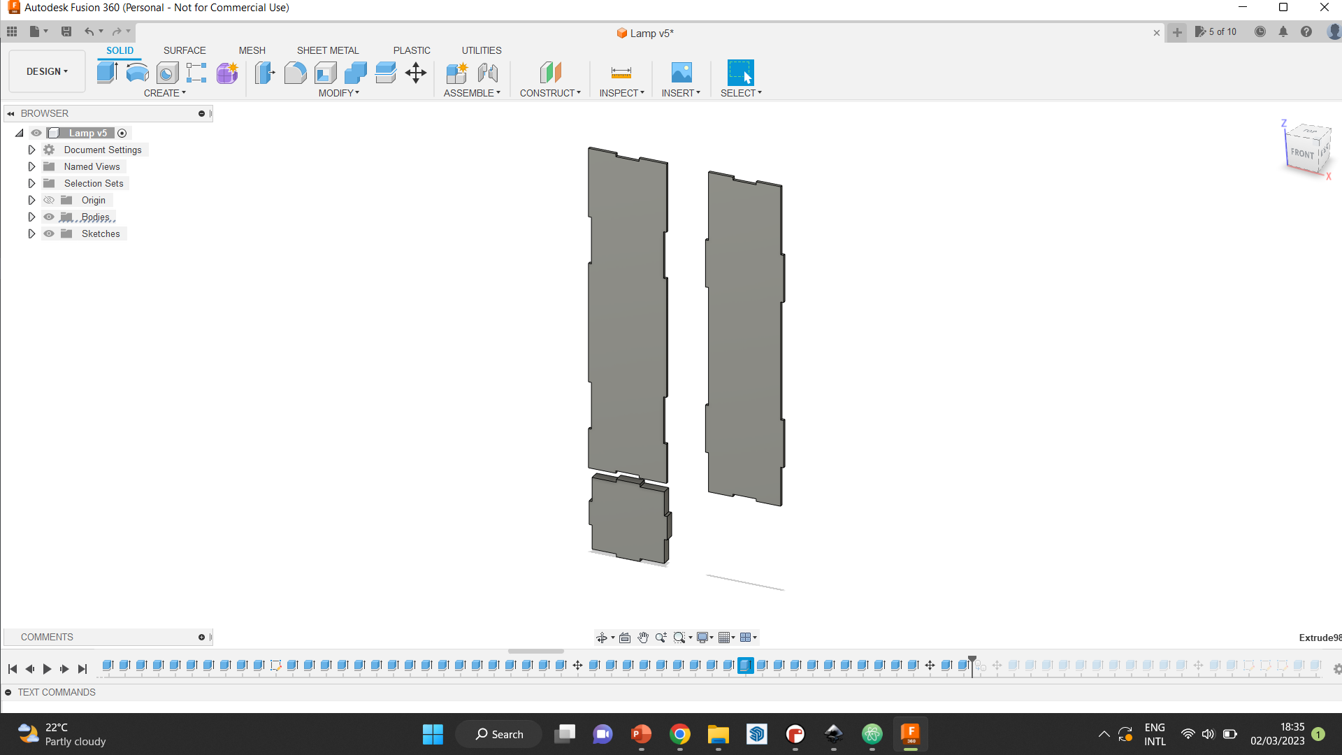
Step 2 Eventhough we loved how it looked, when we tested the area we had to fit the microcontroller and all other electronics, we saw that it would not fit, and that we need a base of atlease 8cm width. So, we widened our design but did not change the height.
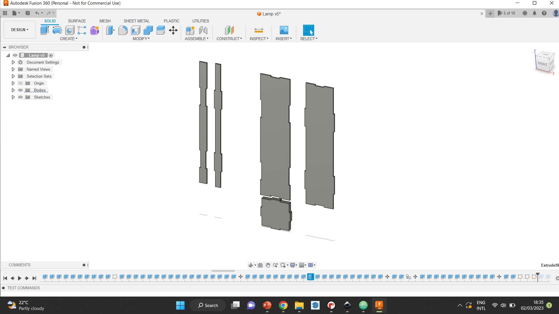
Step 3 With that, we solved the electronics problem, but the design looked very bulky, since the proportion of the height to the width was making it look more cubic than we wanted. To solve that, we made the lamp lengthier. Also, we started thinking more about the placement of the light strip in the lamp. To do that, we decided to create a smaller tube to go inside the bigger encasement.
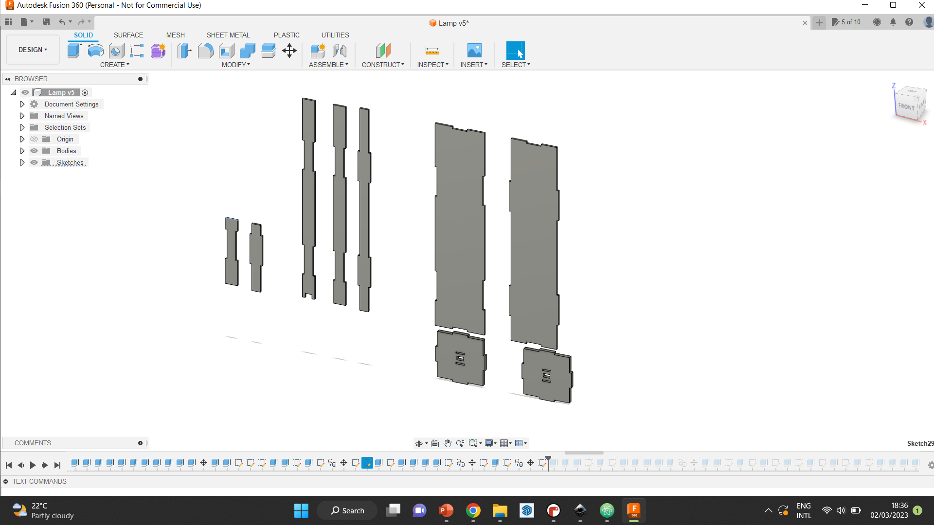
Step 4 At this stage, we were satisfied with how the body of the lamp looked in general. However, we needed to stabalize the center tube, so we created pocket joints in the top and bottom part of the lamp. We also created smaller samples that we used to test the pockets, to prevent material wastage.
Step 5 When the joints worked, we wanted to proceed with the lamp. But at this stage, we got a new idea for the base. Instead of making it with acrylic, we wanted to make it out of wood, and make it a little wider than the top part. This was meant to give it a more sophisticated look, and break the uniformity of the material by adding something that contrasts with it. Therefore, we made on side of the acrylic straight, and removed one of the two coverings made out of acrylic. We also did not want the pocket joints to show at the top for the center, so we made a smaller piece that fits in below the top-most piece, and will hold the tube in place.
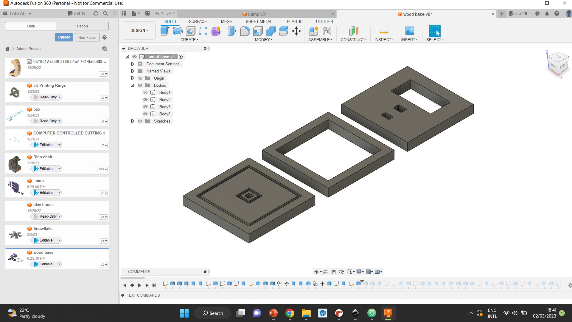
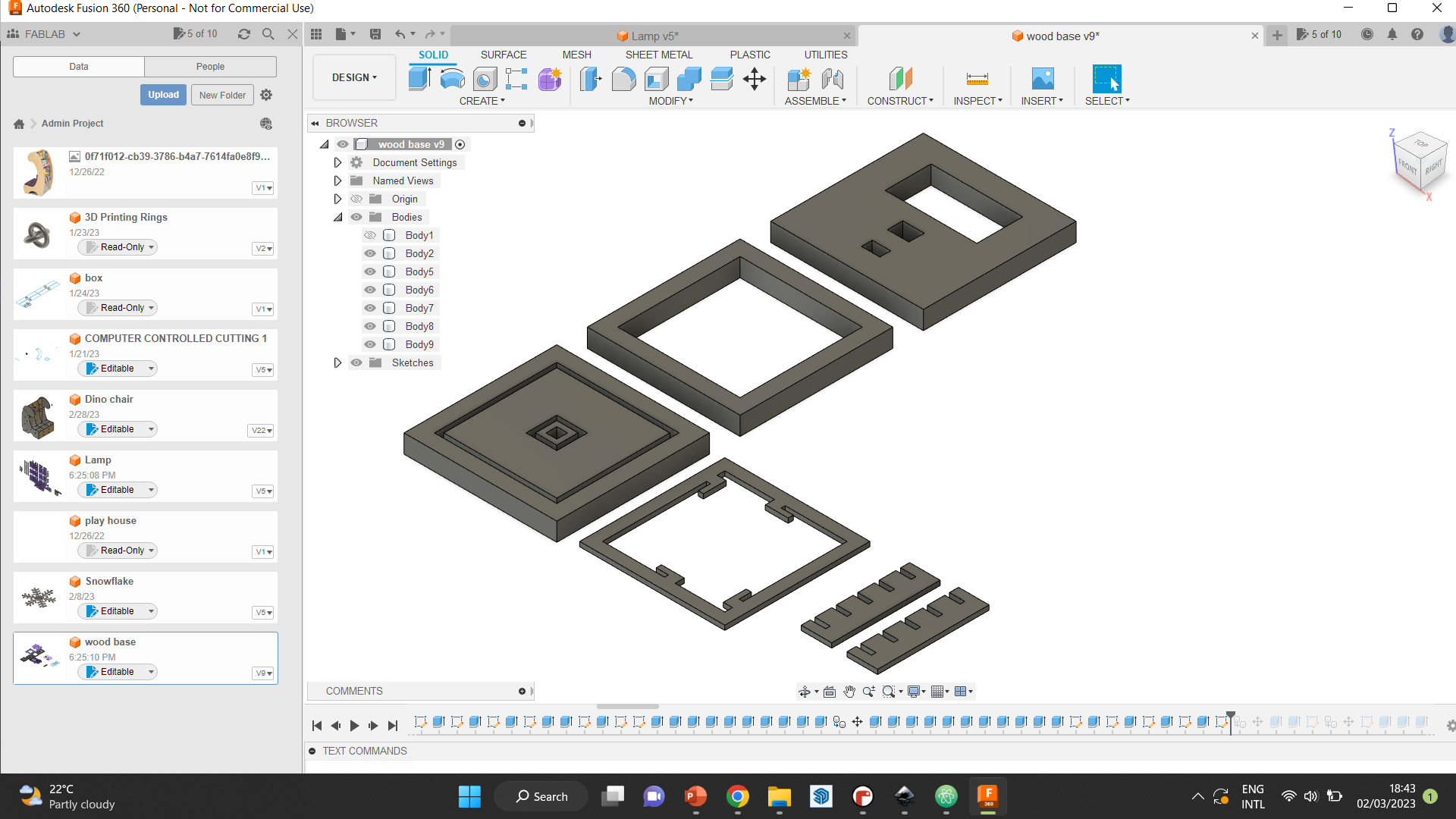
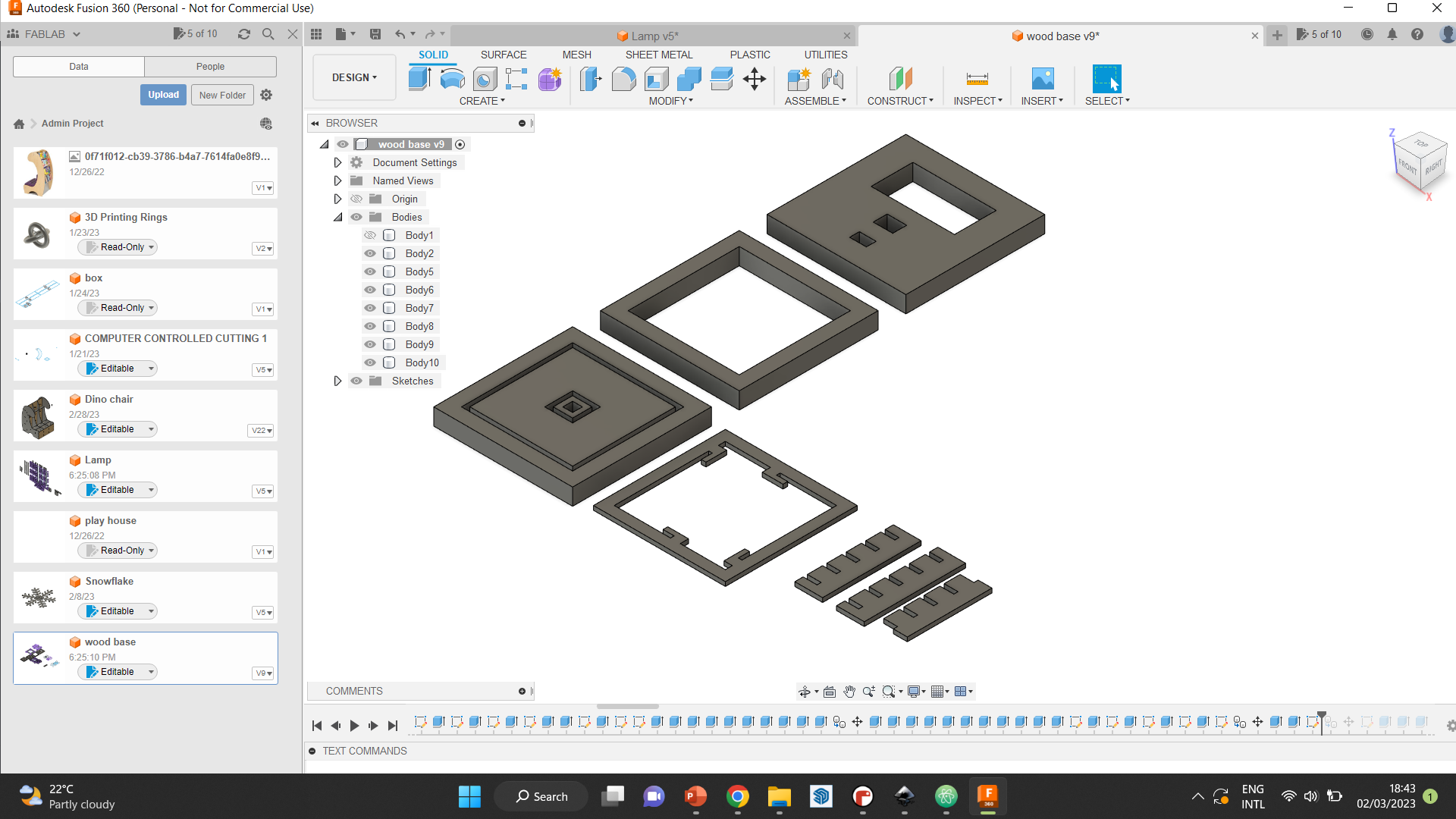
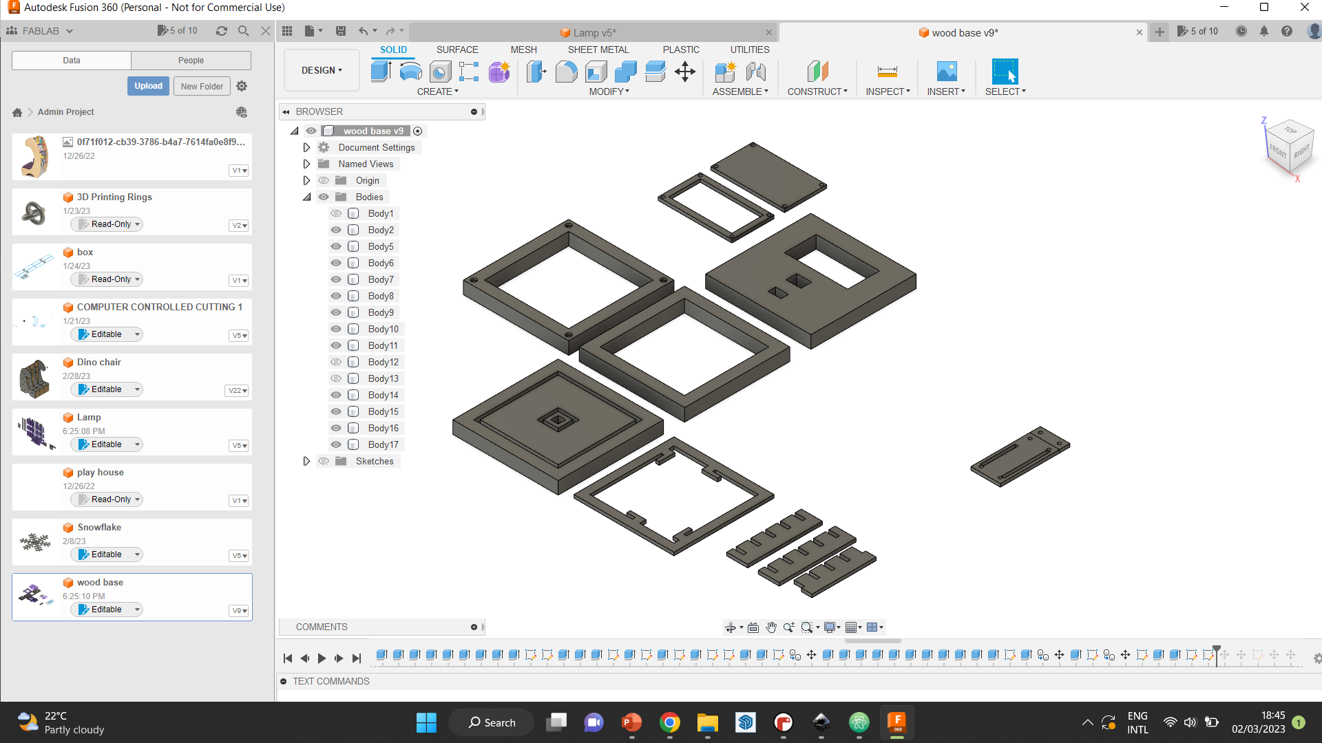
Step 6 Next, we proceeded to make the base. To make the base, we wanted to alternate pieces of wood and acrylic, to give it a more dynamic look, and to lessen the liklihood of it becoming too bulky. Before showing the process, the diagram attached can give an idea of what the final base looks like.
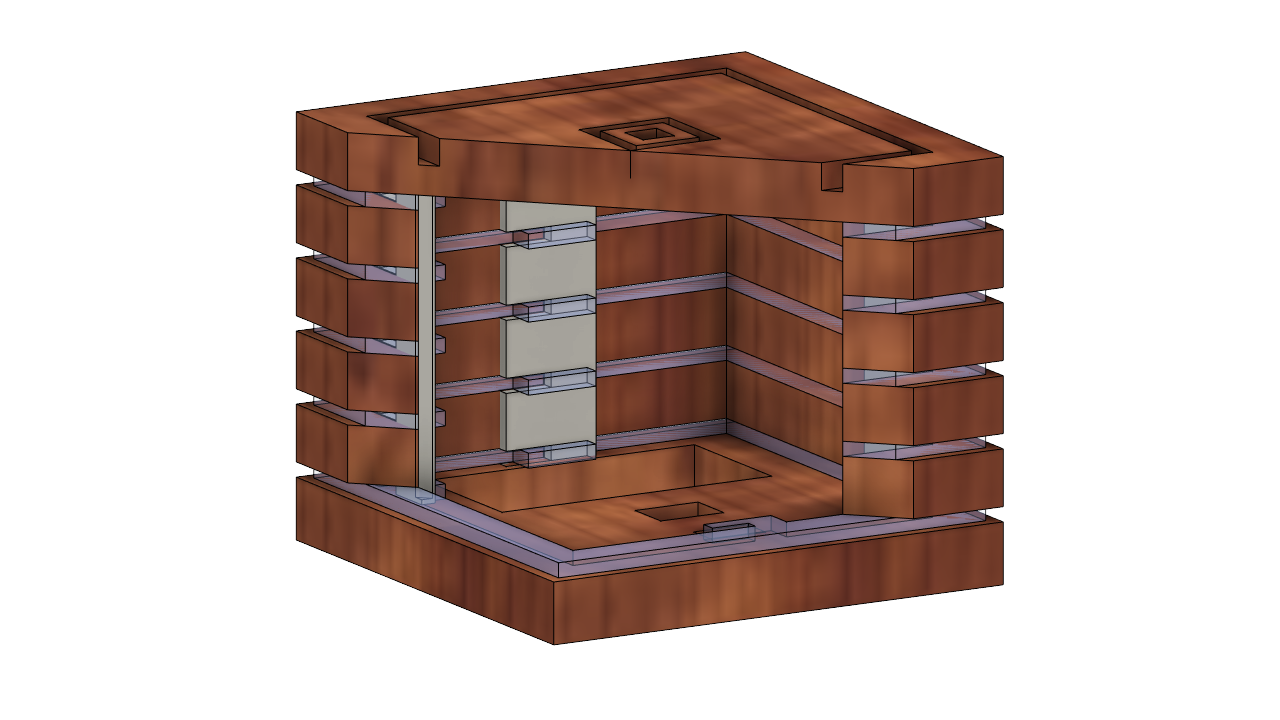
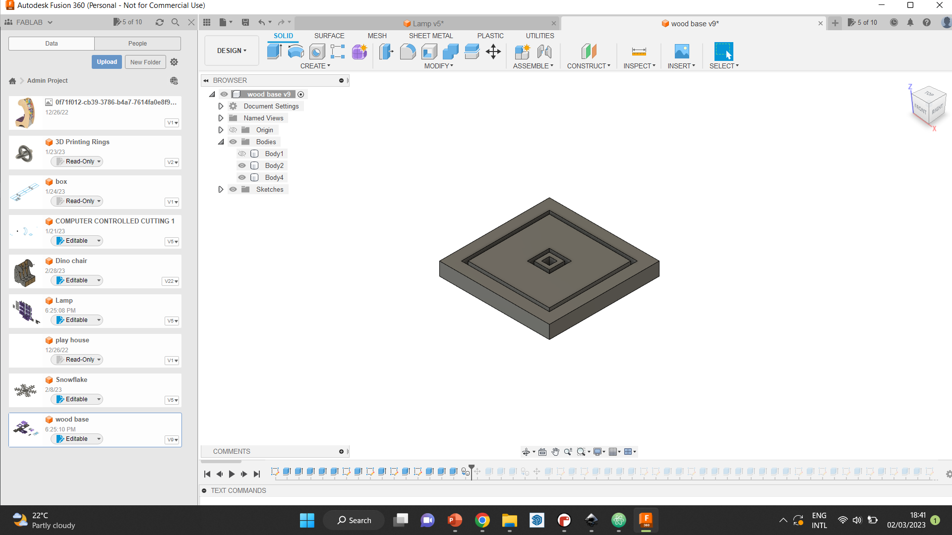
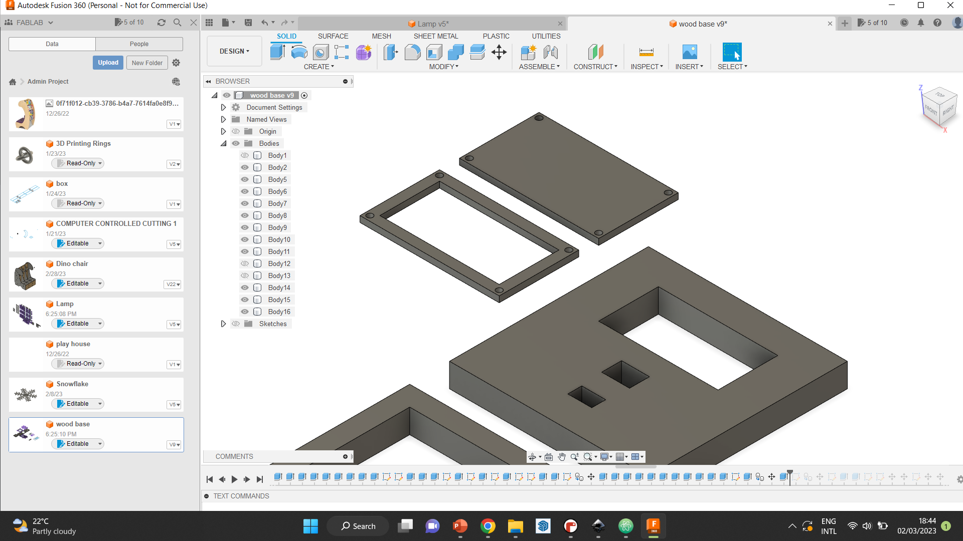
So, to start off, we started by making the main piece, which is the part where the main body of the lamp, as well as the center tube, will be inserted into. The outlines were design to be engraved 6mm deep, and the hole in the middle was to be removed, to connect the light strip to the electronics placed in the base.
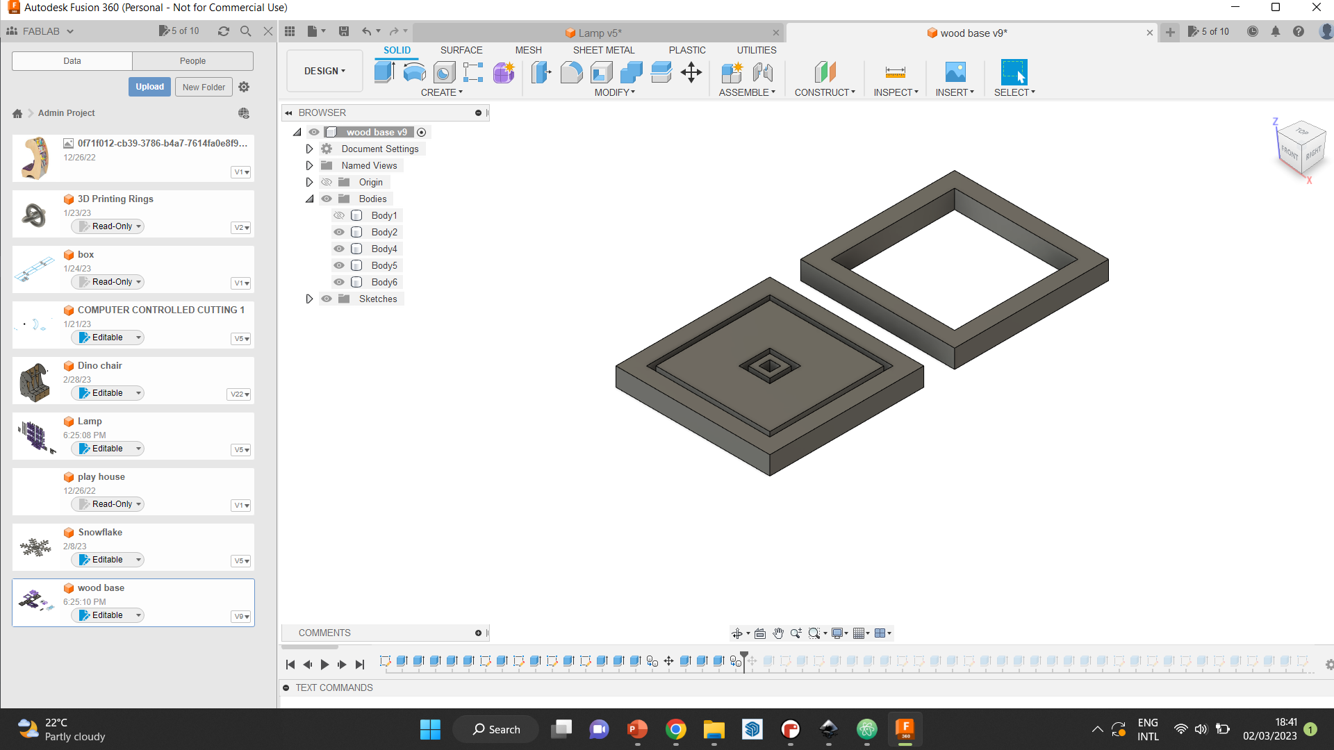
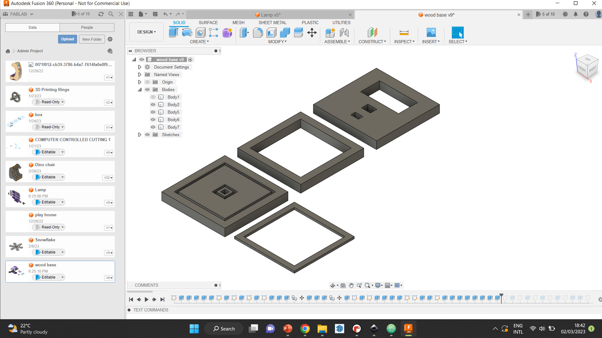
Step 7 We created the pieces that were going to be put as the main part of the base, with a huge hole in the middle where all electronics will fit. We used around 4 layer of this piece in the final design.
Step 8 Then, we worked on the bottom most piece of the base. This piece has three openings for different things. The largest opening was for the batteries, which will allow it to be accessible by the user. The next opening is where the switch will be fixed, and the last is big enough to allow the USB port to reach the microcontroller placed inside, which makes it programmable even after the full assembly.
Step 9 was the acrylic pieces that will go between the wooden layers. We wanted these pieces to hold all of the base pieces together without using glue. So, we made what looks like a comb, to hold the acrylic pieces together from the inside. And since the wooden pieces were in between the acrylic, they will be fixed as well.
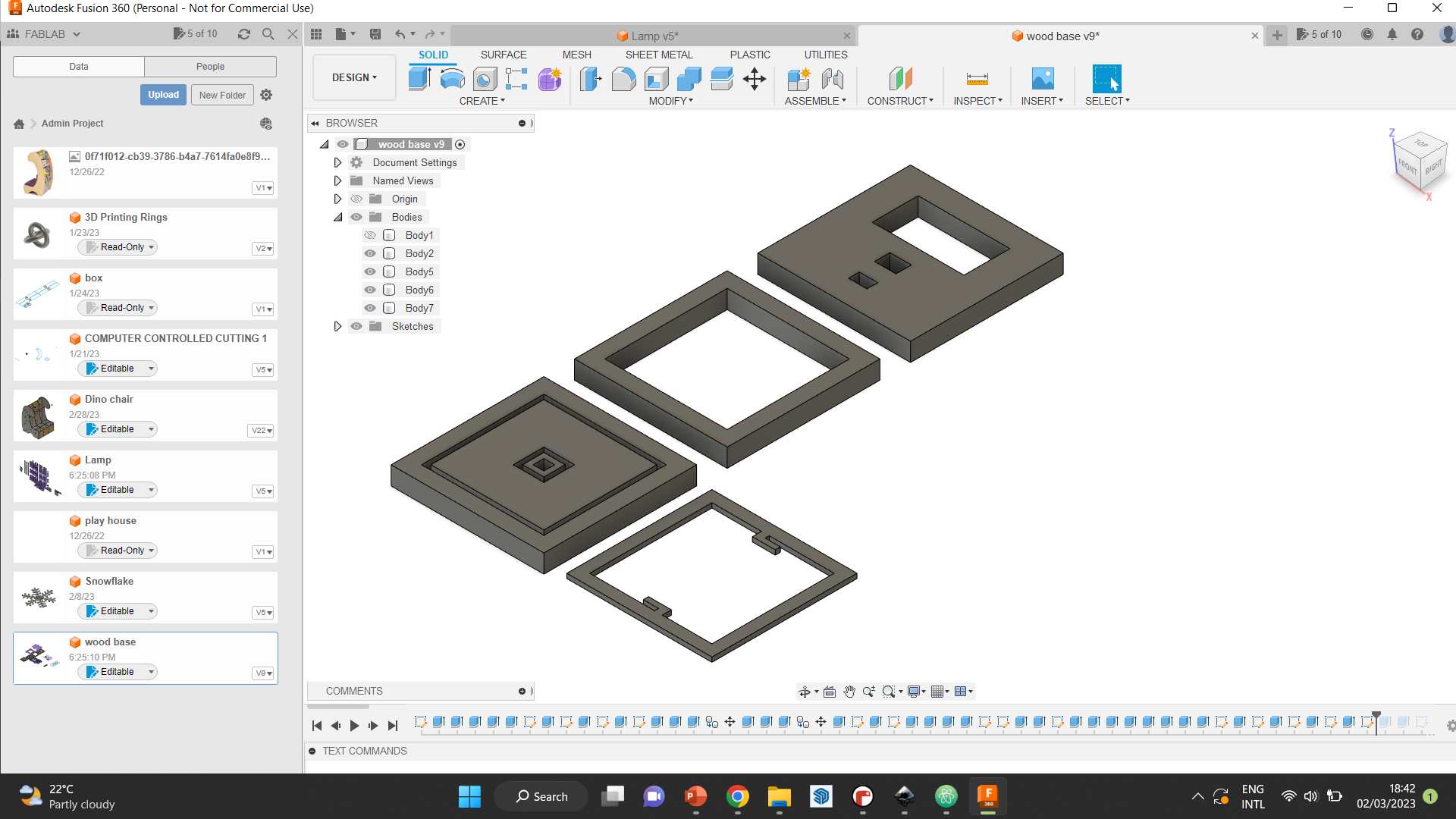
Step 10 After trying the previous step, we noticed two main problems. The first was that the comb needed to have smaller gaps so the pieces wil fit snugly. The other was that it was not stable enough with only two combs. Therefore, we tried to make the comb tighter, and tried two different ones to decide which was better. Then, we added two extra joints to the acrylics, to make them four in total.
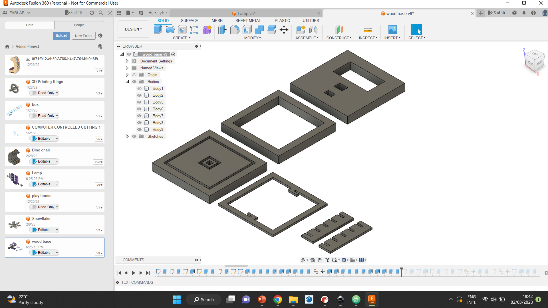
Step 11 Since the joints were perfect at that point, we duplicated on of the combs and removed the top and bottom parts of it. These part were originally done so the comb can fit into the wood, since we made pockets for them. However, since we didn’t take the other two joints into consideration when cutting the wood, and it would not affect the stability, we decided to just remove those parts from the comb. It served the exact same purpose and has just as good of an effect as the others.
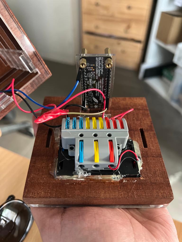
Step 12 With that being done, all the main pieces were designed. Next, we had to focus on the smaller accessories that we needed to add to the design. First, we designed the microcontroller holder. This piece needed to hold the microcontroller inside the base to stabalize it. The cuts in this piece were all done according to the sizes of the microcontroller, so the pins can go through and we can wire it without having any problems.
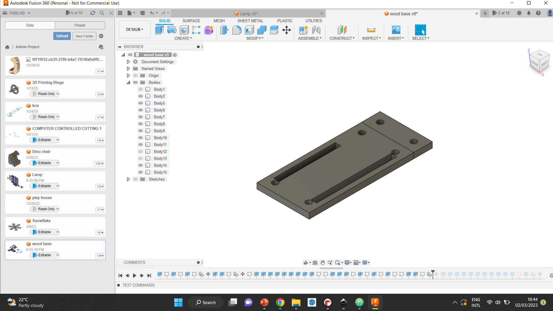
This is how the piece looked in practice.
Step 12 was to create the cover of the batteries, with opening for the screws that will secure it to the base.
Step 13 Finally, we created the last acrylic piece that will go at the very bottom. This piece is meant to elevs=ate the whole light, so the battery cover and the switch have space at the bottom.
Design files
Lamp, including all parts made out of frosted and sanded acrylic, being used for the main lamp part. This file has all drawings excluding those used for the base.
Wooden base, which includes all parts of the base made out of wood. These pieces can be duplicated however needed to get the height desired.
Acrylic base, which are the pieces of acrylic going between the wooden pieces in the base.
Extra acessories such as the microcontroller holder and the battery cover.
Electronics
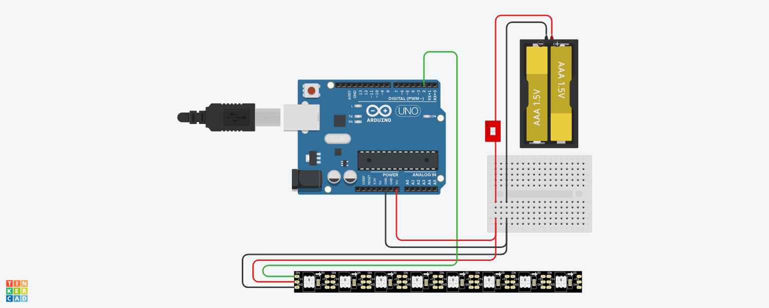
The electronics in this project were fairly simple. We used an RGB strip light, which we connected to an adafruit feather express microcontroller. The whole lamp was battery powered, and had a switch that allows the user to turn it on and off if needed.
All the connections can be seen in the diagram below.
Programming
As the main idea of this light is to act as a mood light with pre-programmed settings, there were several things we had to do to achieve that goal. There were four main things that needed to be tackled in the code, and I will explain each one by itself with an example. At the end, I will add the final code we used.
BLE UART
BLE UART (Bluetooth Low Energy UART) is a wireless communication protocol that allows two devices to communicate with each other using Bluetooth Low Energy (BLE) technology. UART stands for Universal Asynchronous Receiver-Transmitter and it is a standard interface for serial communication between electronic devices.
BLE UART enables a device with a BLE connection to transmit and receive data over a virtual UART interface. This allows devices to communicate with each other in the same way as if they were connected via a physical UART interface, but without the need for any physical wires.
BLE UART is commonly used in applications such as wireless sensor networks, remote control, and monitoring devices. It is also commonly used in Internet of Things (IoT) devices where low power consumption and wireless communication are critical features.
This is the technology used in our Aadafruit microcontroller, which we needed to utilize in order to connect it to the application associated with it.
In our project, we used the pre-made Bluefruit connect application, which is easily downloadable from the app store. We used one of the examples in this link to achieve this part of the code.
The code can be found below.
# SPDX-FileCopyrightText: 2021 ladyada for Adafruit Industries
# SPDX-License-Identifier: MIT

# Print out the color data from ColorPackets.
# To use, start this program, and start the Adafruit Bluefruit LE Connect app.
# Connect, and then select colors on the Controller->Color Picker screen.

from adafruit_ble import BLERadio
from adafruit_ble.advertising.standard import ProvideServicesAdvertisement
from adafruit_ble.services.nordic import UARTService
from adafruit_bluefruit_connect.packet import Packet

# Only the packet classes that are imported will be known to Packet.
from adafruit_bluefruit_connect.color_packet import ColorPacket

ble = BLERadio()
uart_server = UARTService()
advertisement = ProvideServicesAdvertisement(uart_server)

while True:
    # Advertise when not connected.
    ble.start_advertising(advertisement)
    while not ble.connected:
        pass

    while ble.connected:
        packet = Packet.from_stream(uart_server)
        if isinstance(packet, ColorPacket):
            print(packet.color)
Neopixel
NeoPixel is a brand name for a type of addressable LED (light-emitting diode) developed by Adafruit Industries. It is a small, programmable RGB (red, green, blue) LED that can be individually controlled to produce a wide range of colors and effects. NeoPixels are commonly used in hobbyist projects, costumes, and stage lighting because of their flexibility and ease of use. They can be controlled by microcontrollers such as Arduino and Raspberry Pi, and are available in a variety of sizes and configurations. The term “NeoPixel” is often used generically to refer to any addressable LED, but it specifically refers to the Adafruit brand product.
Since we used the LED strip light, we had to use the neopixel code referenced in their official website, which can be seen here.
This is the code we used as a reference.
# SPDX-FileCopyrightText: 2018 Kattni Rembor for Adafruit Industries
#
# SPDX-License-Identifier: MIT

"""CircuitPython Essentials NeoPixel example"""
import time
import board
from rainbowio import colorwheel
import neopixel

pixel_pin = board.A1
num_pixels = 8

pixels = neopixel.NeoPixel(pixel_pin, num_pixels, brightness=0.3, auto_write=False)


def color_chase(color, wait):
    for i in range(num_pixels):
        pixels[i] = color
        time.sleep(wait)
        pixels.show()
    time.sleep(0.5)


def rainbow_cycle(wait):
    for j in range(255):
        for i in range(num_pixels):
            rc_index = (i * 256 // num_pixels) + j
            pixels[i] = colorwheel(rc_index & 255)
        pixels.show()
        time.sleep(wait)


RED = (255, 0, 0)
YELLOW = (255, 150, 0)
GREEN = (0, 255, 0)
CYAN = (0, 255, 255)
BLUE = (0, 0, 255)
PURPLE = (180, 0, 255)

while True:
    pixels.fill(RED)
    pixels.show()
    # Increase or decrease to change the speed of the solid color change.
    time.sleep(1)
    pixels.fill(GREEN)
    pixels.show()
    time.sleep(1)
    pixels.fill(BLUE)
    pixels.show()
    time.sleep(1)

    color_chase(RED, 0.1)  # Increase the number to slow down the color chase
    color_chase(YELLOW, 0.1)
    color_chase(GREEN, 0.1)
    color_chase(CYAN, 0.1)
    color_chase(BLUE, 0.1)
    color_chase(PURPLE, 0.1)

    rainbow_cycle(0)  # Increase the number to slow down the rainbow
Button Packet
The Bluefruit Connect application is a mobile app for iOS and Android that allows you to wirelessly connect to and control Adafruit’s line of Bluefruit boards, which includes microcontrollers with built-in Bluetooth capabilities.
In the context of the Bluefruit Connect app, a button packet is a message that is sent from a Bluefruit board to the app when a button is pressed or released on the board. These packets are typically sent over a Bluetooth connection between the board and the app.
When you use the Bluefruit Connect app to interact with a Bluefruit board, you can configure the board to send button packets whenever a button is pressed or released. The app can then receive and interpret these packets to trigger other actions or events on your phone or tablet.
For example, you might use the Bluefruit Connect app to control a robot or other physical device that is connected to a Bluefruit board. You could configure the board to send button packets whenever you press buttons on the app’s virtual control panel, and use these packets to control the movement of the robot or other device.
Overall, button packets are an important part of the Bluefruit Connect app’s functionality, as they allow you to wirelessly control and interact with physical devices using your smartphone or tablet.
Since the application already has a built-in control pad containing 8 buttons, we used those to control the settings of the light. Each button was meant to trigger a setting for a certain mood. I will explain this further in the final code.
Insert screenshots from application
For this part of the code, we used the example provided in this website. The code is as follows.
# SPDX-FileCopyrightText: 2019 Kattni Rembor for Adafruit Industries
#
# SPDX-License-Identifier: MIT

from adafruit_ble import BLERadio
from adafruit_ble.advertising.standard import ProvideServicesAdvertisement
from adafruit_ble.services.nordic import UARTService

from adafruit_bluefruit_connect.packet import Packet
from adafruit_bluefruit_connect.button_packet import ButtonPacket

ble = BLERadio()
uart = UARTService()
advertisement = ProvideServicesAdvertisement(uart)

while True:
    ble.start_advertising(advertisement)
    while not ble.connected:
        pass

    # Now we're connected

    while ble.connected:
        if uart.in_waiting:
            packet = Packet.from_stream(uart)
            if isinstance(packet, ButtonPacket):
                if packet.pressed:
                    if packet.button == ButtonPacket.BUTTON_1:
                        # The 1 button was pressed.
                        print("1 button pressed!")
                    elif packet.button == ButtonPacket.UP:
                        # The UP button was pressed.
                        print("UP button pressed!")

    # If we got here, we lost the connection. Go up to the top and start
    # advertising again and waiting for a connection.
Color Packet
In Adafruit CircuitPython, a color packet is a message that is sent from a microcontroller or development board to a computer or other device, indicating a specific color value. Color packets are typically used in conjunction with RGB LEDs or other devices that can display colors.
When you create a color object in CircuitPython, you can configure it to generate color packets whenever its color value changes. These packets typically include information such as the ID of the color object, the timestamp of the color change, and the new color value.
In the context of the Bluefruit Connect app, color packets can be used to control the color of an RGB LED connected to a Bluefruit board. You might use the app’s color picker feature to select a specific color, which generates a color packet that is sent to the board. The board can then use this packet to set the color of the RGB LED to the selected value.
Overall, color packets are a useful feature of Adafruit CircuitPython that can help you control the color of RGB LEDs or other devices using microcontrollers and development boards. In the context of the Bluefruit Connect app, color packets allow you to wirelessly control the color of physical devices using your smartphone or tablet.
We added this feature in the light to allow the user to have an alternative to the pre-programmed light settings. In this feature, they have the freedom to choose the color and its brightness.
For this, we used this code as an example, taken from here.
# SPDX-FileCopyrightText: 2020 ladyada for Adafruit Industries
# SPDX-License-Identifier: MIT

# CircuitPython NeoPixel Color Picker Example

import board
import neopixel

from adafruit_bluefruit_connect.packet import Packet
from adafruit_bluefruit_connect.color_packet import ColorPacket

from adafruit_ble import BLERadio
from adafruit_ble.advertising.standard import ProvideServicesAdvertisement
from adafruit_ble.services.nordic import UARTService

ble = BLERadio()
uart_service = UARTService()
advertisement = ProvideServicesAdvertisement(uart_service)

pixels = neopixel.NeoPixel(board.NEOPIXEL, 10, brightness=0.1)

while True:
    # Advertise when not connected.
    ble.start_advertising(advertisement)
    while not ble.connected:
        pass
    ble.stop_advertising()

    while ble.connected:
        if uart_service.in_waiting:
            packet = Packet.from_stream(uart_service)
            if isinstance(packet, ColorPacket):
                print(packet.color)
                pixels.fill(packet.color)
Final code
After understanding each part of the code individually, we proceeded to merge them together in a way that makes them work simultaneously. As mentioned previously, there are four parts that needed to be included, and the code below includes all of them.
As for the button packet, which includes 8 buttons, each button has a specific mode as shown. These modes each have a specific RGB number based on research, each associated with its respective button in the code. The function of each button is shown in this table below. The color modes are all shown in my classmate’s website mentioned in the beginning. They can be found by following this link.
| Button | Function |
|---|---|
| 1 | Induces sleep and promotes relaxation |
| 2 | Helps improve focus and concentration |
| 3 | Provides relief for migraine headaches |
| 4 | Helps promote relaxation and stress relief |
| Right | Activates Reading mode |
| Left | Activates Screen Time mode |
| Up | Increases brightness |
| Down | Decreases brightness |
import board
import neopixel

from adafruit_bluefruit_connect.packet import Packet
from adafruit_bluefruit_connect.color_packet import ColorPacket
from adafruit_bluefruit_connect.button_packet import ButtonPacket

from adafruit_ble import BLERadio
from adafruit_ble.advertising.standard import ProvideServicesAdvertisement
from adafruit_ble.services.nordic import UARTService
R = 0
B = 0
G = 0
Rmain = 0
Bmain = 0
Gmain = 0
ble = BLERadio()
uart_service = UARTService()
advertisement = ProvideServicesAdvertisement(uart_service)
pixels = neopixel.NeoPixel(board.D2, 48 , brightness=1)

while True:
    # Advertise when not connected.
    ble.start_advertising(advertisement)
    while not ble.connected:
        pass
    ble.stop_advertising()

    while ble.connected:
        if uart_service.in_waiting:
            packet = Packet.from_stream(uart_service)
            if isinstance(packet, ColorPacket):
                print(packet.color)
                pixels.fill(packet.color)

            if isinstance(packet, ButtonPacket):
                if packet.pressed:
                    if packet.button == ButtonPacket.BUTTON_1:
                        # The 1 button was pressed (Sleep).
                        print("1 button pressed!")
                        #pixels.fill((73, 100, 187))
                        Rmain = 73; Bmain = 187; Gmain = 100;
                        R= 73;  B = 187; G = 100;
                        pixels.fill((Rmain, Gmain, Bmain))
                    elif packet.button == ButtonPacket.BUTTON_2:
                        # The 2 button was pressed (Focus).
                        print("2 button pressed!")
                        #pixels.fill((255, 163, 70))
                        Rmain = 255; Bmain = 70; Gmain = 163;
                        R= 255;  B = 70; G = 163;
                        pixels.fill((Rmain, Gmain, Bmain))
                    elif packet.button == ButtonPacket.BUTTON_3:
                        # The 3 button was pressed (Headache).
                        print("3 button pressed!")
                        #pixels.fill((18, 39, 0))
                        Rmain = 18; Bmain = 0; Gmain = 39;
                        R= 18;  B = 0; G = 39;
                        pixels.fill((Rmain, Gmain, Bmain))
                    elif packet.button == ButtonPacket.BUTTON_4:
                        # The 4 button was pressed (Relax). - purple-ish
                        print("4 button pressed!")
                        #pixels.fill((122, 40, 152))
                        Rmain = 122; Bmain = 152; Gmain = 40;
                        R= 122;  B = 152; G = 40;
                        pixels.fill((Rmain, Gmain, Bmain))
                                            pixels.fill((R, G, B))
                    elif packet.button == ButtonPacket.LEFT:
                        # The LEFT button was pressed (Screentime).
                        print("LEFT button pressed!")
                        #pixels.fill((133, 70, 19))
                        Rmain = 133; Bmain = 19; Gmain = 70;
                        R= 133;  B = 19; G = 70;
                        pixels.fill((Rmain, Gmain, Bmain))
                    elif packet.button == ButtonPacket.RIGHT:
                        # The RIGHT button was pressed (Reading).
                        print("RIGHT button pressed!")
                        #pixels.fill((87, 35, 3))
                        Rmain = 87; Bmain = 3; Gmain = 35;
                        R= 87;  B = 3; G = 35;
                        pixels.fill((Rmain, Gmain, Bmain))
                    elif packet.button == ButtonPacket.UP:
                    # The UP button was pressed (inc brightness).
                    print("UP button pressed!")
                    #pixels.fill((73, 100, 187))
                    if R != Rmain or B != Bmain or G != Gmain :
                        print("not equal!")
                        #pixels.fill((Rmain, Gmain, Bmain))
                        R = R*2
                        G = G*2
                        B = B*2
                        pixels.fill((R, G, B))
                    elif packet.button == ButtonPacket.DOWN:
                        # The DOWN button was pressed (dec brightness).
                        print("DOWN button pressed!")
                        R = R/2
                        G = G/2
                        B = B/2
After the code was programmed into the light, we were able to control it through the application smoothly. The video attached shows how it works.
This first video shows the button packet, and how each button has a specific program.
This second video shows the color packet, where the user can pick the color and brightness they prefer.