Final Project
This is my final project documentation of electronics and softwares for the Amachine project.
Research
GRBL is an open source firmware for motor control of CNC machines.
G-code is a programming language to tell a what movment to perform.
G-code sender is a software on the computer to send the g-code file line by line to the CNC machine.
electronics
For the main board we have to use a microcontroller compatible with grbl firmware which is an open source software for motoin control of CNC machines.

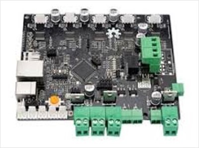
We had two options which is atmega328(arduino uno) or a 3d printer controller board that has an atmega2560 which is the same chip in the arduino mega. The second option seems to be better since it has all the stepper drivers connections ready.
However, the connections might be diffrent than the default one in the grbl firmware and the other extera connections like temperture sensors and filemnt coneections.
In the end we decided to use the arduino uno with a cnc shield which has the same connections as the default grbl firmware.
To upload the firmware download the grbl from here, Add the grbl library and open the example ‘grblUpload’ and upload it.
We connected t a single stepper motor driver to the arduino uno and opened the serial monitor and sent a g-command ‘G00 X100’ which is instrucion to tell it to move 100 mm in the x direction.
Not that the pin configuration can be viewed or modified from the cpu_map.h file.
idealy to drive two stepper motors in one axis a jumpers has to be placed to clone an axis to the ‘A’ axis and use the other motor for it because one a4988 driver cant drive two motors.
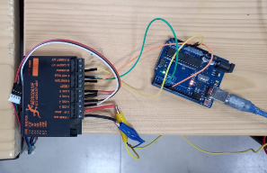
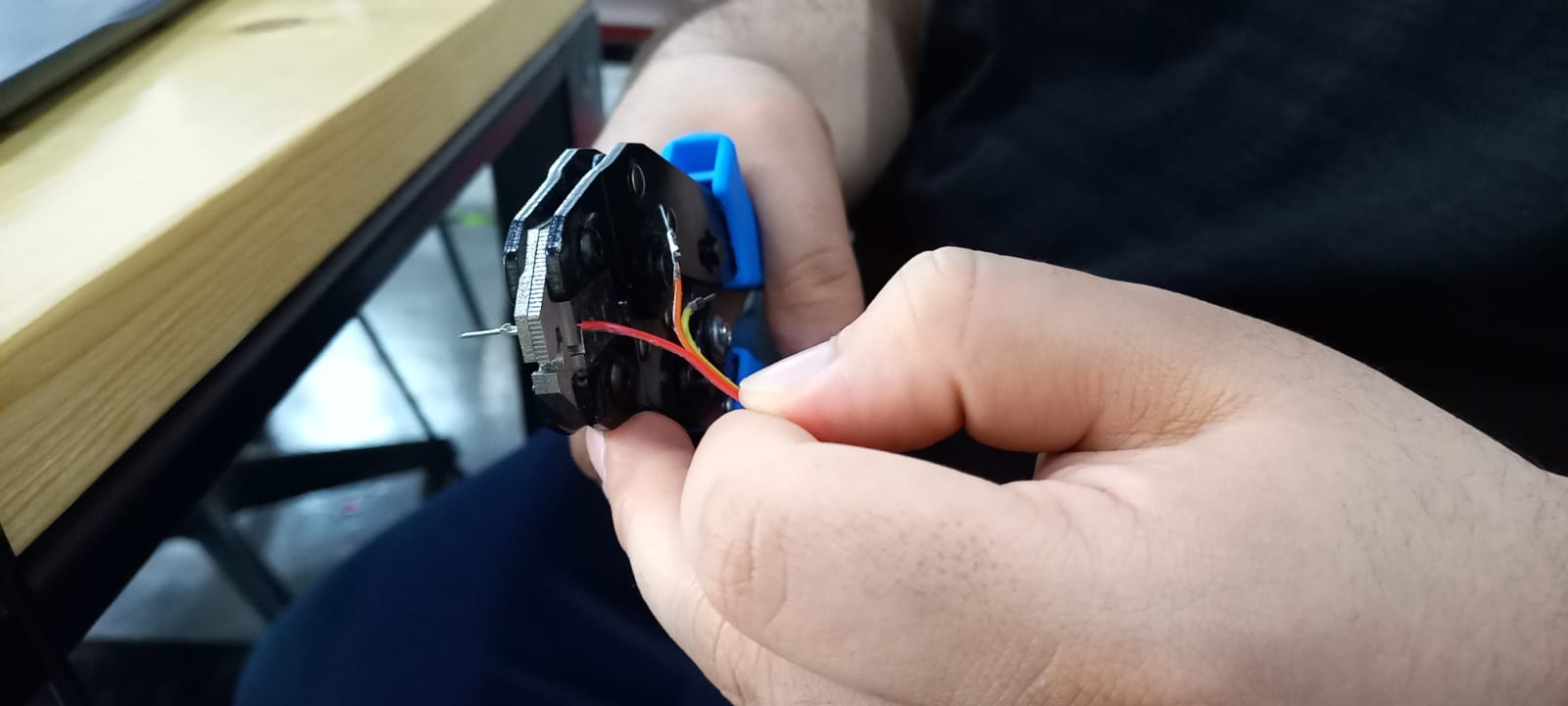
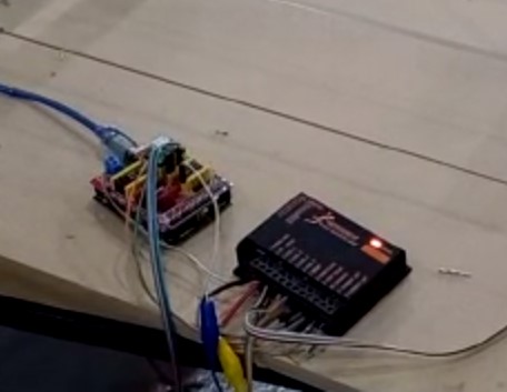
but due to lack of stepper drivers I connected a Geckodrive driver to drive two motors for the y-axis and one a4988 driver for the x-axis. To connect the motors I used a crimping tool to connect male and female connectors for easy connections and longer wires.
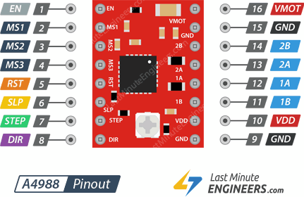
To connect the Geckodrive driver to the shield I used the a4988 driver pinout layout to connect just 3 wires (Step, Dir, GND)
for more information about A4988 stepper driver follow this link
Next we tested the motor spining direction to correct it if needed by flipping the connector. Then we set the grbl settings of the step per mm ratio by simple methode: 1-Send g-code to move 100mm (G00 X100) 2-measure the distance travel 3-calculate the ratio. Actual ratio = ratio*100/traveled distance .
to set grbl settings we used the universal g-code sender and the command list
to view the grbl settings send $$.
And then we attached a coloring pen to it and started drawing.
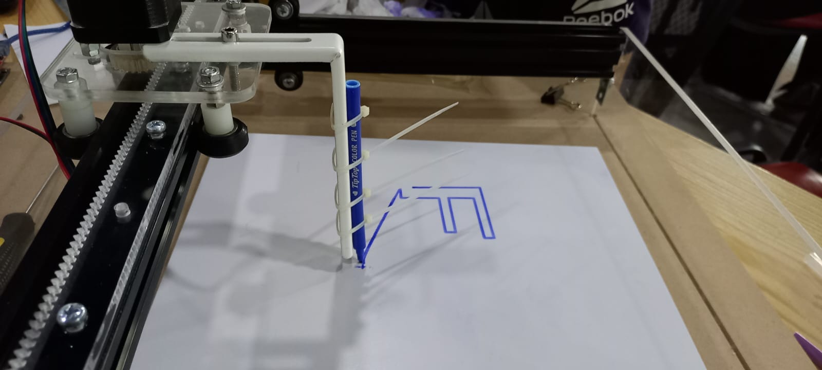
We installed limit switches at the x and y axises and enabled homing cycle in grbl setting. The home position was in the buttom right and it sould be on the left so the designs is mirrored. Also we had to correct the homing direction in the settings. Homing worked well but every time the controller is reseted it get locked due to alarm error so we had to unlock it every time using ($X) command. we disabled the homing and we dont get this error anymore.
We didnt have much time to make a z axis and decided to use a modified version of grbl that uses a servo motor as a z axis. All details on how to do it are here.
We had some problems where the pen we used was very tough for the servo motor and after searching in we found the perfect one. The servo is rotating from 0 to 20 degrees to move the pen and write.
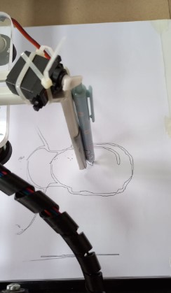
This methode uses the commands ‘M05’ and ‘M03’ to control the z axis which is a command for turnning on/off the spindle and it wont work other than this methode with this firmware.
This is the grbl settings
>>> $$
$0 = 10    (step pulse, usec)
$1 = 25    (step idle delay, msec)
$2 = 0    (step port invert mask:00000000)
$3 = 0    (dir port invert mask:00000000)
$4 = 0    (step enable invert, bool)
$5 = 0    (limit pins invert, bool)
$6 = 0    (probe pin invert, bool)
$10 = 3    (status report mask:00000011)
$11 = 0.010    (junction deviation, mm)
$12 = 0.002    (arc tolerance, mm)
$13 = 0    (report inches, bool)
$20 = 0    (soft limits, bool)
$21 = 0    (hard limits, bool)
$22 = 0    (homing cycle, bool)
$23 = 3    (homing dir invert mask:00000011)
$24 = 25.000    (homing feed, mm/min)
$25 = 500.000    (homing seek, mm/min)
$26 = 250    (homing debounce, msec)
$27 = 1.000    (homing pull-off, mm)
$100 = 21.000    (x, step/mm)
$101 = 13.000    (y, step/mm)
$102 = 250.000    (z, step/mm)
$110 = 50000.000    (x max rate, mm/min)
$111 = 50000.000    (y max rate, mm/min)
$112 = 500.000    (z max rate, mm/min)
$120 = 10.000    (x accel, mm/sec^2)
$121 = 10.000    (y accel, mm/sec^2)
$122 = 10.000    (z accel, mm/sec^2)
$130 = 200.000    (x max travel, mm)
$131 = 200.000    (y max travel, mm)
$132 = 200.000    (z max travel, mm)
Softwares
For the g-code sender I used Candle and universal g-code sender. Both worked well but candle was sometimes buggy and doesnt always visualise the g-code, So I used UGS.
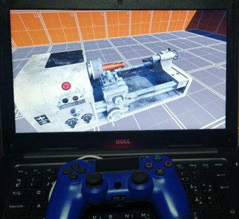
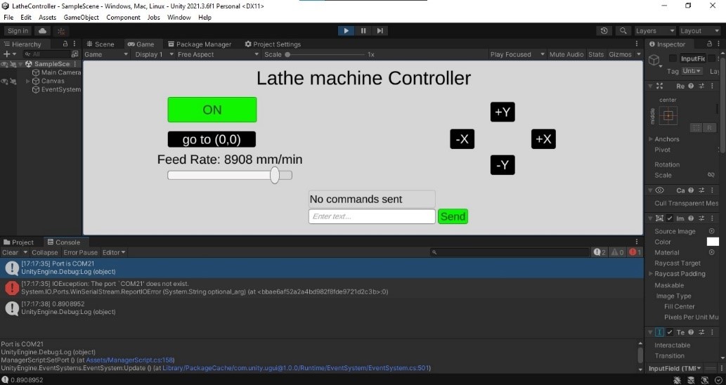
We got some suggestions from instructors to make the machine work wirelessly in local and global network with the ability to control it with a joystick.
All the available controlling programs does not have these things, so I had to make my own g-code sender software but before that I made a simulation do demonstrate how hard and impractical to use a joystick for such a machine.
I created a computer vision program in python for a safety feature in the machine. The program is detecting hands and measure the distance from it to the machine and do an action like alarm or emergency stop.
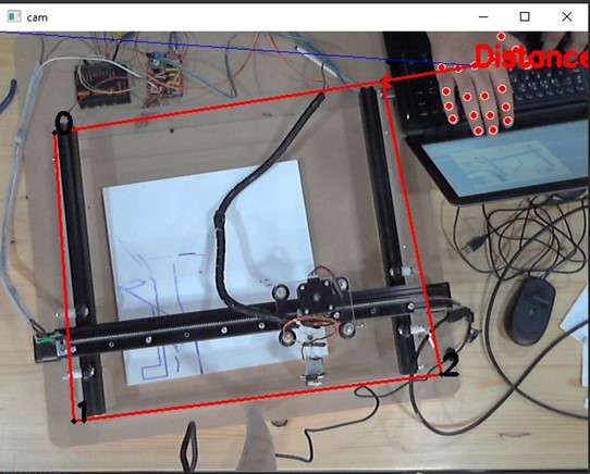
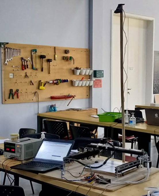
The camera is installed in on a stick
I using opencv for image processing and drawing

and pygame library to play the alarm sound since it is the only library that can do it without freezing the program.
I am using mediapipe library for the hand detection it is very relaiable and easy to use.

This is the code I wrote, it works well just define the four corners and it wll start the detection. However, it has some bugs and some inefficincy issues and needs some modifications.
import math
from pygame import mixer
import cv2 as cv
import mediapipe as mp

#meiapipe initilization
mpHands = mp.solutions.hands
hands = mpHands.Hands(max_num_hands=4,min_detection_confidence=0.7)
mpDraw = mp.solutions.drawing_utils

#initlize sounds
mixer.init()
sound = mixer.Sound('errorSound.mp3')


# cam things
cam = 1
video = cv.VideoCapture(cam,cv.CAP_DSHOW)

# mouse things
xp = []
yp = []
mouseX = 0
mouseY = 0
clicks = 0

#ui
drawn = False
color = (0,255,0)


def click(event, x, y, flags, param):
    global clicks, mouseX, mouseY, drawn
    mouseX = x
    mouseY = y
    if event == cv.EVENT_LBUTTONDOWN:
        if drawn is False:
            xp.append(x)
            yp.append(y)
            clicks = clicks + 1

#read first frame
frameAvailable, frame = video.read()


cv.imshow('cam', frame)
cv.setMouseCallback("cam", click)

while frameAvailable:
    # read frame
    frameAvailable, frame = video.read()

    #detection
    imageRGB = cv.cvtColor(frame, cv.COLOR_BGR2RGB)
    results = hands.process(imageRGB)


    # draw lines
    if len(xp) > 1:
        for i in range(len(xp)):
            p1 = (xp[i], yp[i])
            if len(xp) > i + 1:
                p2 = (xp[i + 1], yp[i + 1])
            cv.line(frame, p1, p2, (0, 0, 255), 2)

    # complete rectangle
    if len(xp) == 4:
        xp.append(xp[0])
        yp.append(yp[0])
        drawn = True
    elif len(xp) != 0 and drawn is False:
        # draw to mouse if not completed
        cv.line(frame, (xp[len(xp) - 1], yp[len(xp) - 1]), (mouseX, mouseY), (0, 0, 255), 2)
    if drawn:

        # checking whether a hand is detected
        if results.multi_hand_landmarks:
            for handLms in results.multi_hand_landmarks:  # working with each hand
                for id, lm in enumerate(handLms.landmark):
                    h, w, c = frame.shape
                    cx, cy = int(lm.x * w), int(lm.y * h)
                    mpDraw.draw_landmarks(frame, handLms)
                    if id == 9:
                        lm9x, lm9y = cx, cy
                    elif id == 0:
                        lm0x, lm0y = cx, cy
                r = int(math.sqrt((lm9x - lm0x) * (lm9x - lm0x) + (lm9y - lm0y) * (lm9y - lm0y)))
                xpos, ypos = lm9x, lm9y

                pDis = []
                #calculate distances
                for i in range(len(xp) - 1):
                    #draw
                    cv.circle(frame, (xp[i], yp[i]), 1, 0,4)
                    cv.putText(frame, str(i), (xp[i], yp[i]), cv.FONT_HERSHEY_SIMPLEX, 1, 0, 3)
                    #calculate distance from points to position
                    pDis.append(math.sqrt((xp[i] - xpos) * (xp[i] - xpos) + (yp[i] - ypos) * (yp[i] - ypos)))

                #find closest points
                tempList = pDis.copy()
                tempList.sort()
                p1Ind = pDis.index(tempList[0])
                p2Ind = pDis.index(tempList[1])
                #calculate the equation of the line
                m1 = (yp[p2Ind] - yp[p1Ind]) / (xp[p2Ind] - xp[p1Ind]+0.0001)
                b1 = (yp[p1Ind] - m1 * xp[p1Ind])
                m2 = (-1 / (m1+0.0001))
                b2 = ypos - (m2 * xpos)
                LinePointx = (-b1 + b2) / (m1 - m2)
                LinePointy = m2 * LinePointx + b2
                lineDis = math.sqrt((LinePointx - xpos) * (LinePointx - xpos) + (LinePointy - ypos) * (LinePointy - ypos))
                shortLinePt = (int(LinePointx),int(LinePointy))
                #find length of the border
                borderLength = math.sqrt((xp[p2Ind]-xp[p1Ind])*(xp[p2Ind]-xp[p1Ind]) + (yp[p2Ind]-yp[p1Ind])*(yp[p2Ind]-yp[p1Ind]))
                #detect if the point is on the border


                if pDis[p2Ind] >= borderLength\
                        :
                    cv.arrowedLine(frame,(xpos, ypos), (xp[p1Ind],yp[p1Ind]), color, 2)
                    Distance = pDis[p1Ind]
                else:
                    # draw the perpendcualar
                    cv.arrowedLine(frame,(xpos, ypos), shortLinePt, color, 2)
                    Distance = lineDis

                #print distance
                cv.putText(frame, 'Distance: ' + str(int(lineDis)), (xpos, ypos), cv.FONT_HERSHEY_SIMPLEX, 1, color, 3)

                cv.line(frame, (0, 0), (xpos, ypos), (255, 0, 0), 1)

                #draw to line or a point
                if Distance <= 100:
                    color = (0,0,255)  # red
                    sound.play()
                elif Distance <= 150:
                    color = (0,255,255)   #green
                else:
                    color = (0,255,0)   #green


    cv.imshow('cam', frame)

    if cv.waitKey(1) & 0xff == ord('q'):
        break
video.release()
cv.destroyAllWindows()
See this link to know how to use mediapipe library to detect hands.
How to use it
send file
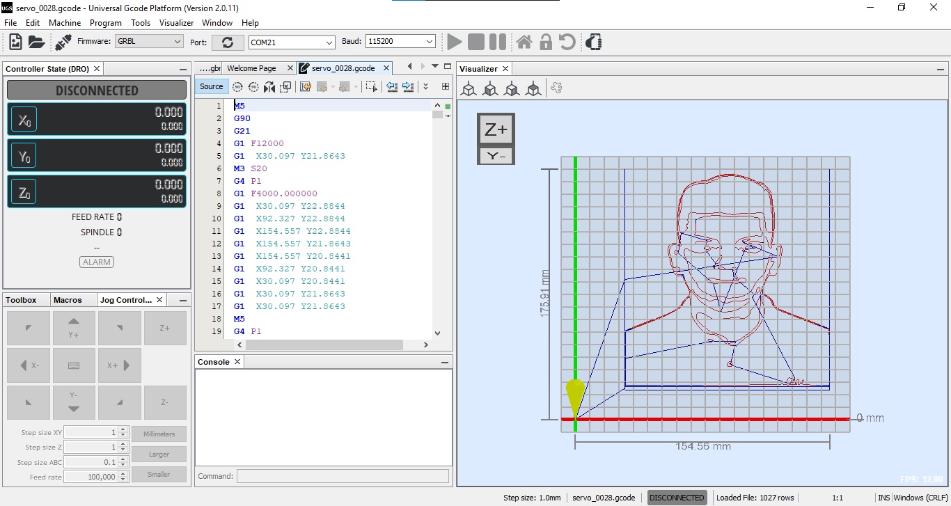
To use the machine download universal g-code sender. Note that the program has no installation, it can be opened by the icon in the bin folder.
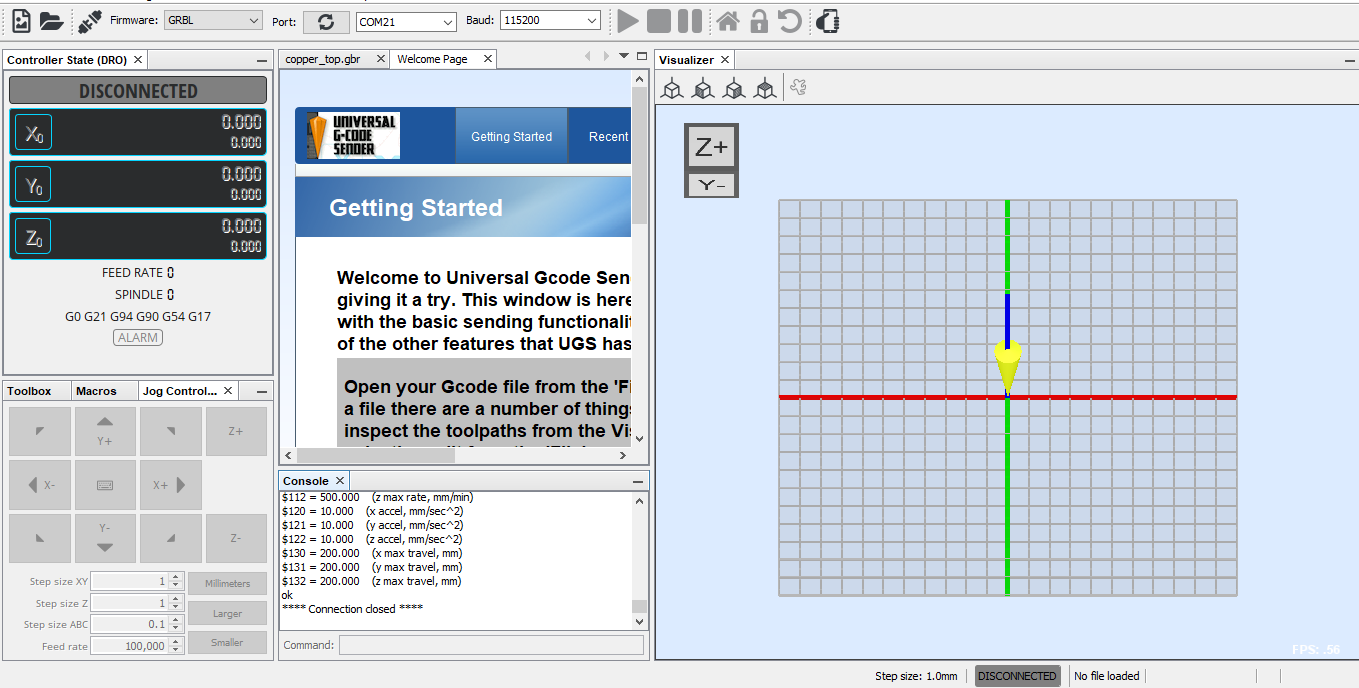
To connect to the grbl board you have to define the COM port and baud rate as shown. After that press the connect icon to connect to the board. Note that the COM is diffrent from one user to other.

You should get something like this. if you got any errors make sure you choosed the correct COM port and no other programs are using the same port.

open the g-code file by clicking on the open icon.
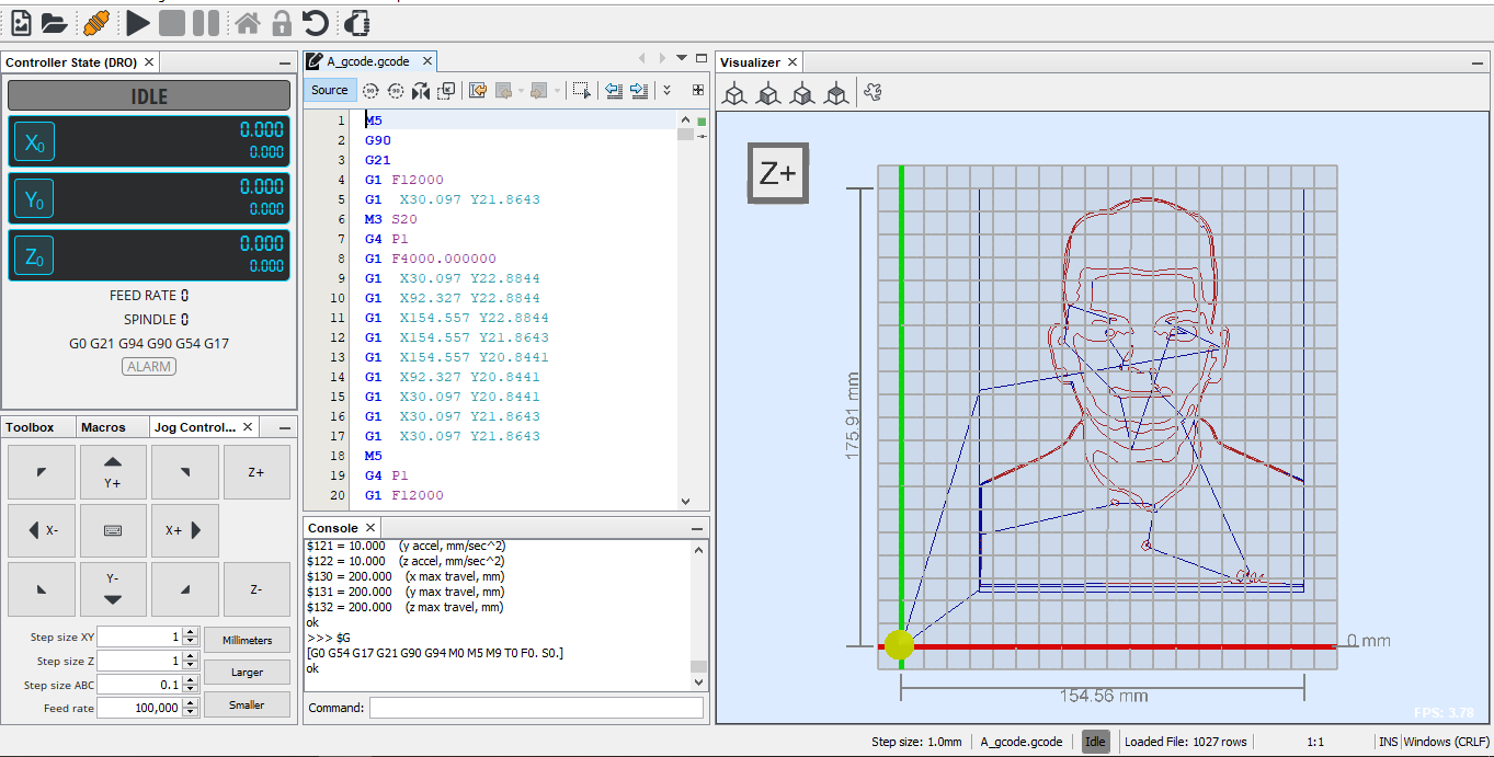
and this is a demo g-code Download g-code. For this code stick a paper on the machine and while the corner is on the pen origin.

Now turn on the power supply at 25V and send the g-code file by clicking on the start icon. But first make sure that the machine is on the 0, 0 position. if it is not then turn off the power supply and move it maniually to the bottom right corner. Also, make sure that the g-code area is less than the paper you are using.

after that the machine will start drawing.
generate your own g-code
This machine will not work on any gcode, it has to be this methode since we are using a modified version of grbl that uses the spindle commands to control the servo motor.
Tips: The machine has some tolerance in the gears and the steps to mm ratios are approxiamted so it fails to draw very small details.
Try to create contious lines in the design for faster drawing.
mirror your design because the machine is mirrored.
installation
Download MIGRBL extention for inkscape
After installing Inkscape unzip the extention files and place it in this directory
C:\Program Files (x86)\Inkscape\share\extensions
if every thing is correct you should have this option
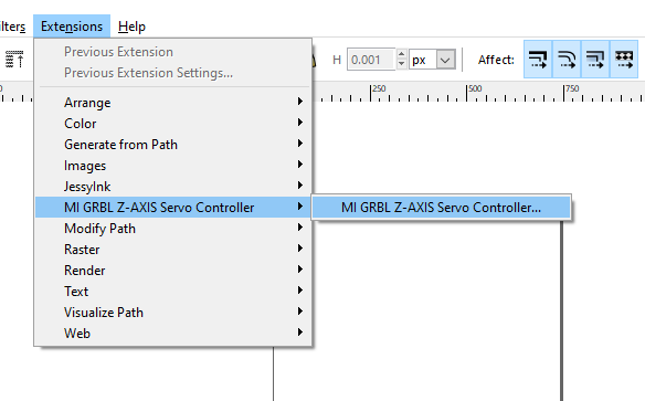
image processing
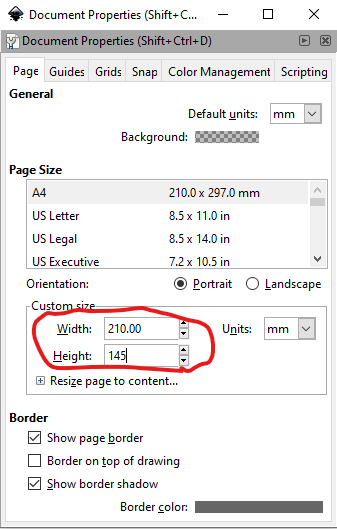
first step is to set the size of your paper. to do that go to file>Document properties and set the unit to mm then set the size of the paper.
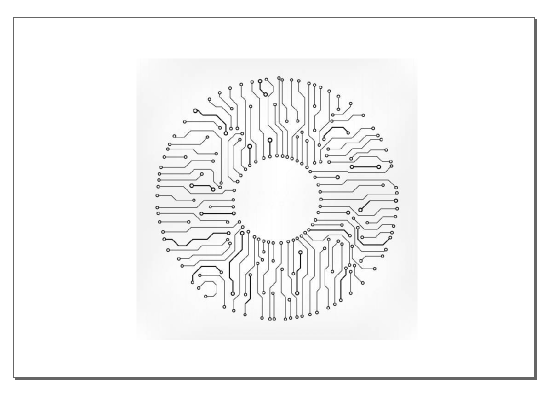
place your image on Inkscape, resize it and place it where you want. I am using this image

click on path>trace bit map and click ok. if the image is not good some values can be adjusted until you get a resonable one.
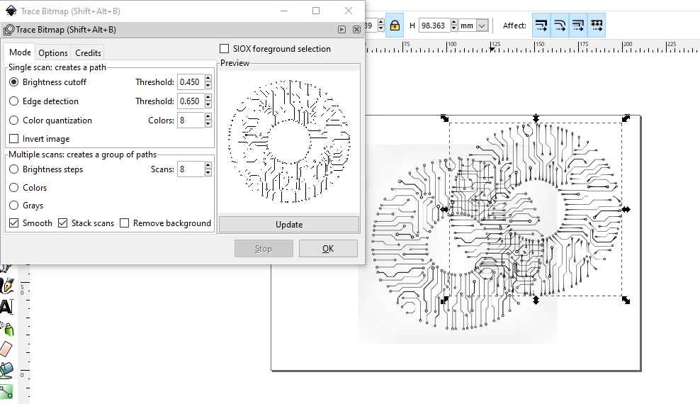
Now a bit map will be generated on the image, delete the image and place the bit map where it should be. Next click on path>object path

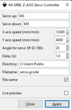
To export the gcode go to extentions>MI GRBL Z-Axis servo controller. a window will pop,change the servo angle to 20 degrees. Also, change the speed to go faster.
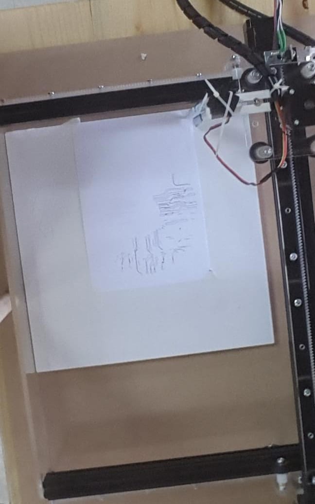
This image was to test the machine with small details. it cant do the small lines correctly and I stopped the process due to this.
Now the file is ready to be sent,Default location where you find the generated G code is C:\Users\Public. Follow this link for the original tutorial