7. Input & Output device
In this week, I learned how to differentiate and program input and output sensors.
Microcontrollers
Microcontrollers are compressed microcomputers used to control embedded systems in office equipment, robots, home appliances, automobiles, and a variety of other devices. Memory, peripherals, and, most crucially, a CPU are all included in a microcontroller.
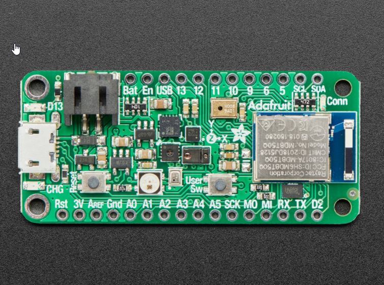
The image was taken from this website: https://learn.adafruit.com/adafruit-feather-sense
Breadboard
A breadboard makes it simple and quick to build temporary electronic circuits or conduct circuit design experiments. Because of the rows and columns of internally connected spring clips beneath the perforated plastic container, breadboards make it simple for developers to connect components or wires.
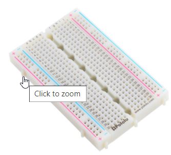 The image was taken from this website:
https://www.pololu.com/product/4000
The image was taken from this website:
https://www.pololu.com/product/4000
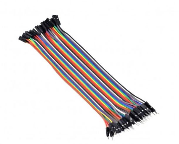
Jumper wires
Jumper wires are used in circuits to link two terminals. Jumper wire is available from All Electronics in a number of lengths and assortments. Often used in connection with breadboards and other prototyping tools to make it simple to update a circuit as needed.
Input sensors
Sensors are devices that perform a “Input” function by “sensing” a physical change in some characteristic that changes in response to some stimulation, such as heat or force, and converting it to an electrical signal. After collecting the data it gets transmitted to the computer. Because this is usually an analogue signal, it must be converted to digital data before being processed by the computer. An Analogue-to-Digital Converter is used to do this (ADC).
Output devices
The output device shows the result of the computer’s processing of raw data entered by an input device. There are several output devices that show output in a variety of formats, including text, photos, hard copies, audio, and video.
Ultrasonic & buzzer circuit
In the mini project, I used the following materials: 1.Breadboard
2.Adafruit feather sense
3.Jumper wires
 The image was taken from this website:
https://www.twinschip.com/Jumper_Wires40Female_to_Male
The image was taken from this website:
https://www.twinschip.com/Jumper_Wires40Female_to_Male
4.Ultrasonic sensor
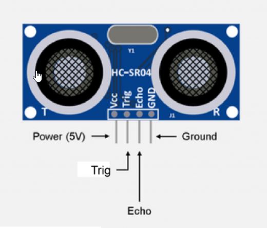 The image was taken from this website:
https://osoyoo.com/2018/09/18/micro-bit-lesson-using-the-ultrasonic-module/
The image was taken from this website:
https://osoyoo.com/2018/09/18/micro-bit-lesson-using-the-ultrasonic-module/
5.Buzzer
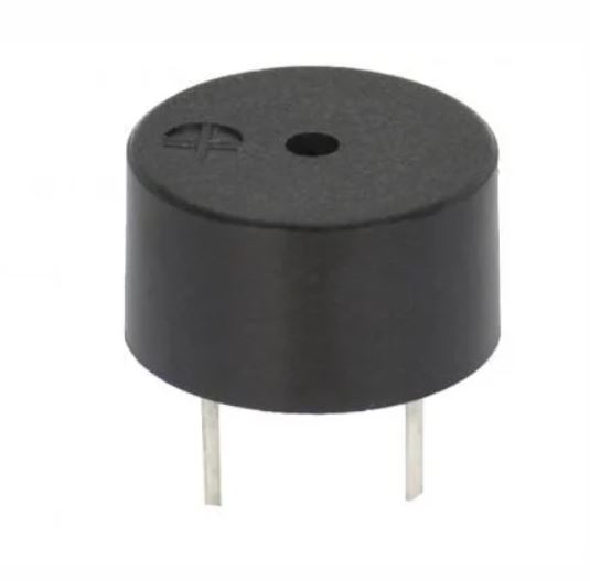 The image was taken from this website:
https://subscription.packtpub.com/book/hardware_and_creative/9781785884818/6/ch06lvl1sec45/make-some-noise
The image was taken from this website:
https://subscription.packtpub.com/book/hardware_and_creative/9781785884818/6/ch06lvl1sec45/make-some-noise
6.LED pin
 The image was taken from this website:
https://makecode.adafruit.com/learnsystem/pins-tutorial/devices/led-connections
The image was taken from this website:
https://makecode.adafruit.com/learnsystem/pins-tutorial/devices/led-connections
Programming and the wire connections
This is the circuit diagram
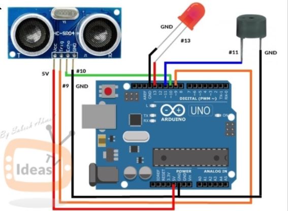
This is the code you’re required to upload into the adafruit feather sense.
#include <SoftwareSerial.h>

// defines pins numbers
const int trigPin = 9;
const int echoPin = 10;
const int buzzer = 11;
const int ledPin = 13;

// defines variables
long duration;
int distance;
int safetyDistance;


void setup() {
pinMode(trigPin, OUTPUT); // Sets the trigPin as an Output
pinMode(echoPin, INPUT); // Sets the echoPin as an Input
pinMode(buzzer, OUTPUT);
pinMode(ledPin, OUTPUT);
Serial.begin(9600); // Starts the serial communication
}


void loop() {
// Clears the trigPin
digitalWrite(trigPin, LOW);
delayMicroseconds(2);

// Sets the trigPin on HIGH state for 10 micro seconds
digitalWrite(trigPin, HIGH);
delayMicroseconds(10);
digitalWrite(trigPin, LOW);

// Reads the echoPin, returns the sound wave travel time in microseconds
duration = pulseIn(echoPin, HIGH);

// Calculating the distance
distance= duration*0.034/2;

safetyDistance = distance;
if (safetyDistance <= 5){
  digitalWrite(buzzer, HIGH);
  digitalWrite(ledPin, HIGH);
}
else{
  digitalWrite(buzzer, LOW);
  digitalWrite(ledPin, LOW);
}

// Prints the distance on the Serial Monitor
Serial.print("Distance: ");
Serial.println(distance);
}
heroshot
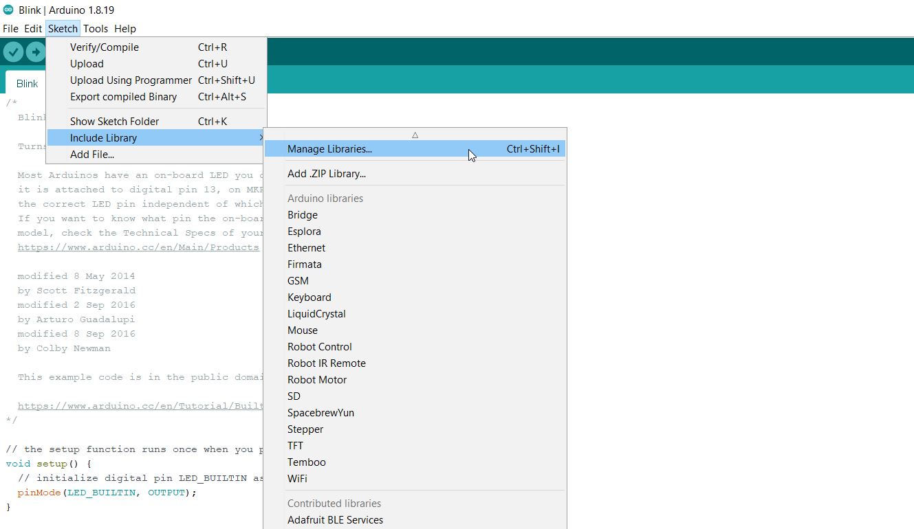
Problem faced
The arduine software couldn’t recognise the serial command. Therefore, you need to download ‘softwareserial’ from the library manager.