2. Computer Aided design
This week I worked on defining my final project idea and started to getting used to the documentation process.
Research
Computer-aided design (CAD) is using computer to digitally create 2D or 3D designs for products before being manufactured. It replaces manual drawing and drafting for better documentation. It also aids in optimization, modification, and analysis of these designs. There is wide variety of CAD software. Some are for beginners, professionals, designers, or even drafters. Some CAD software are special for a specific field like mechanical, electrical, civil engineering, and other than engineering fields like industrial or medical related things. The software used in this task is Autodesk Inventor specifically version 2019. Autodesk Inventor is a CAD application developed by Autodesk. It is made specifically to aid in mechanical designs, simulations, and documentations. 32

This is the home page, where you can create new part, assembly, drawing, or presentation or you can open an existing file. At the bottom you will see the recent documents you opened. 1

2D Design
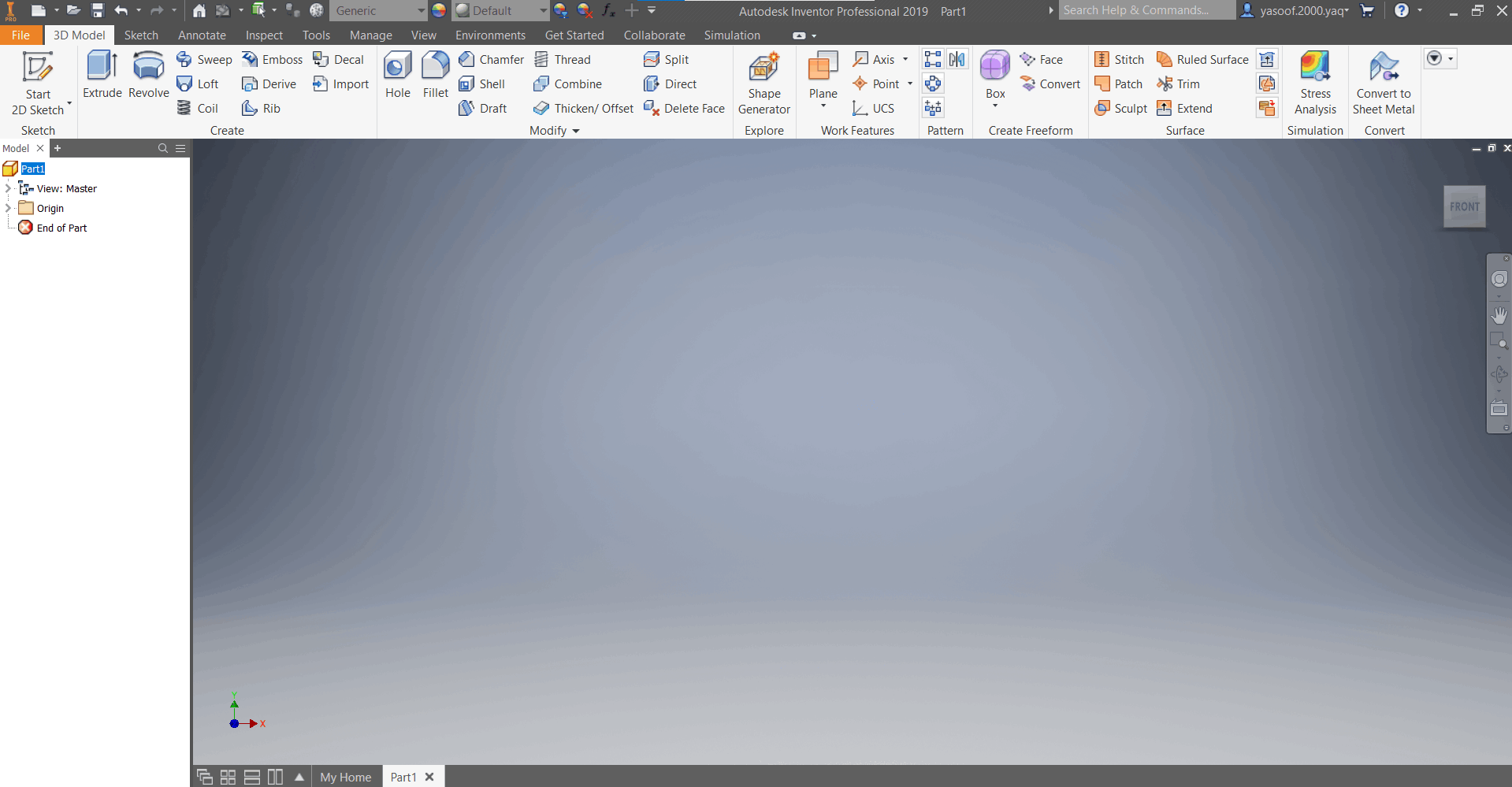
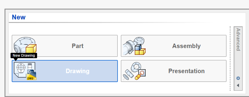
1- If you want to create a new drawing you can either make it in Drawing or Part. If you are going to create your drawing on a Part, you can convert it then to a Drawing. In this example I will create my drawing on Part and then convert it to a Drawing because it is almost the same thing plus, you will get to know how to convert a part to a drawing. So, just click on Part or click on New Part. 2

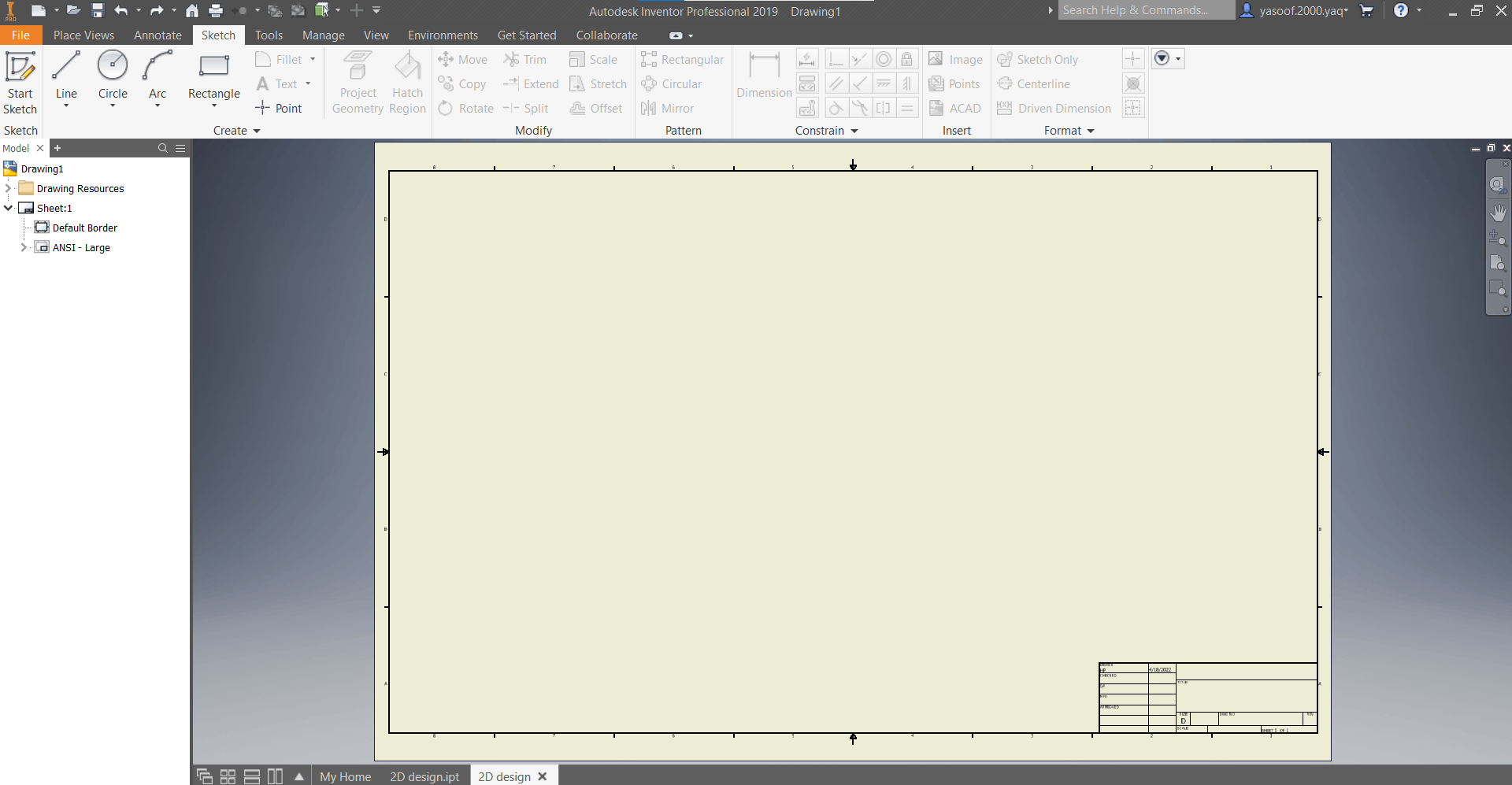
2- When this page appears, click on Start 2D Sketch. 3
3- One difference between a Drawing and a Part is that you have to choose a plane to draw on first because it is a 3D space where in Drawing mode you only draw in 2D (one plane). Choose any plane for now. 4
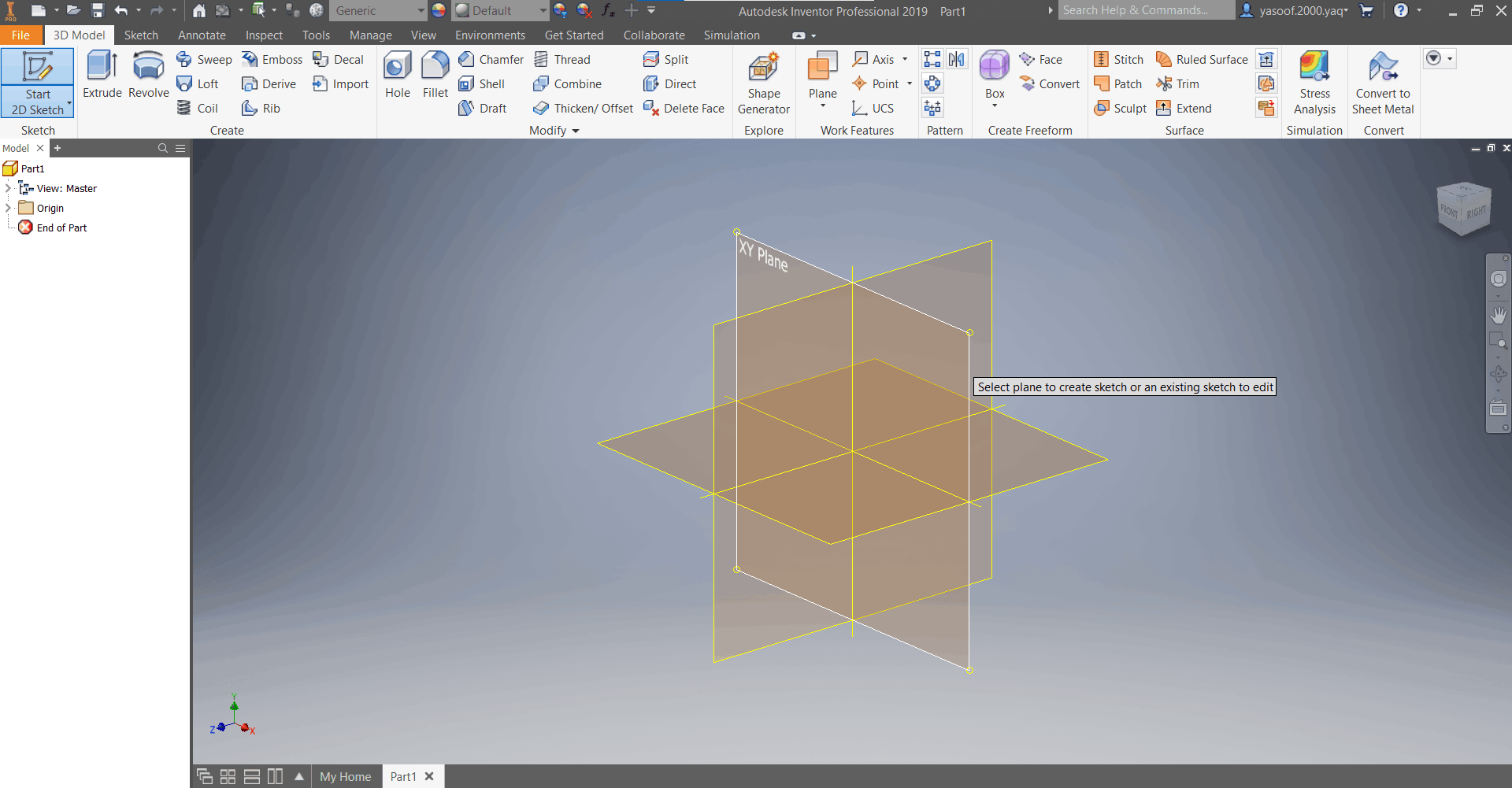
4- At the top you can see the tools you can use to draw. The center which is shown as small yellow dot is the origin. 5

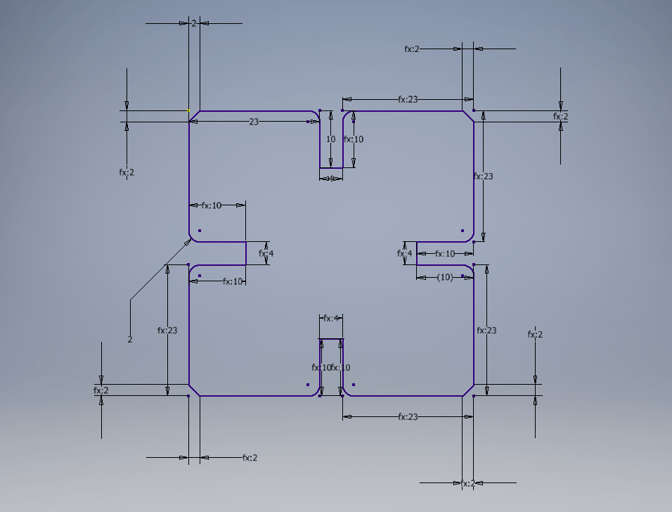
5- When you put the pointer on any of the tools, you will see an explanation of what it does and how to use it. 6

6- I drew this shape using line, fillet, and chamfer functions. You can also make the same shape with rectangle or other function. A drawing can be drawn with many different functions. Note that it is important to set the dimensions of your drawing. 7

7- once done from the drawing click on Finish Sketch. 8
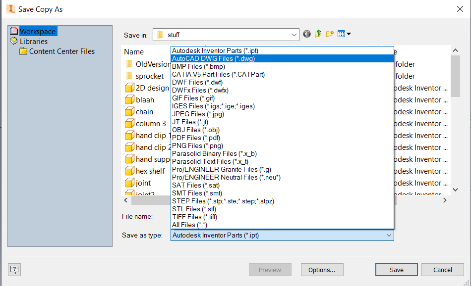
8- Now you can either export your sketch as a drawing directly or you can save it as a drawing. 9-10-11

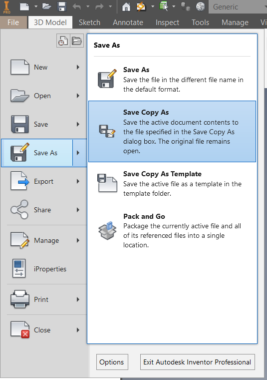
9- You can also create a 2D drawing using Drawing which only has a 2D workspace. However, if you want to make a 3D part from your drawing you will have to copy it and paste it in Part which has a 3D workspace. 12-13
10- Always remember to save before, while, and after drawing. Because sometimes the software can stop responding or you just never know what would happen.
3D Design
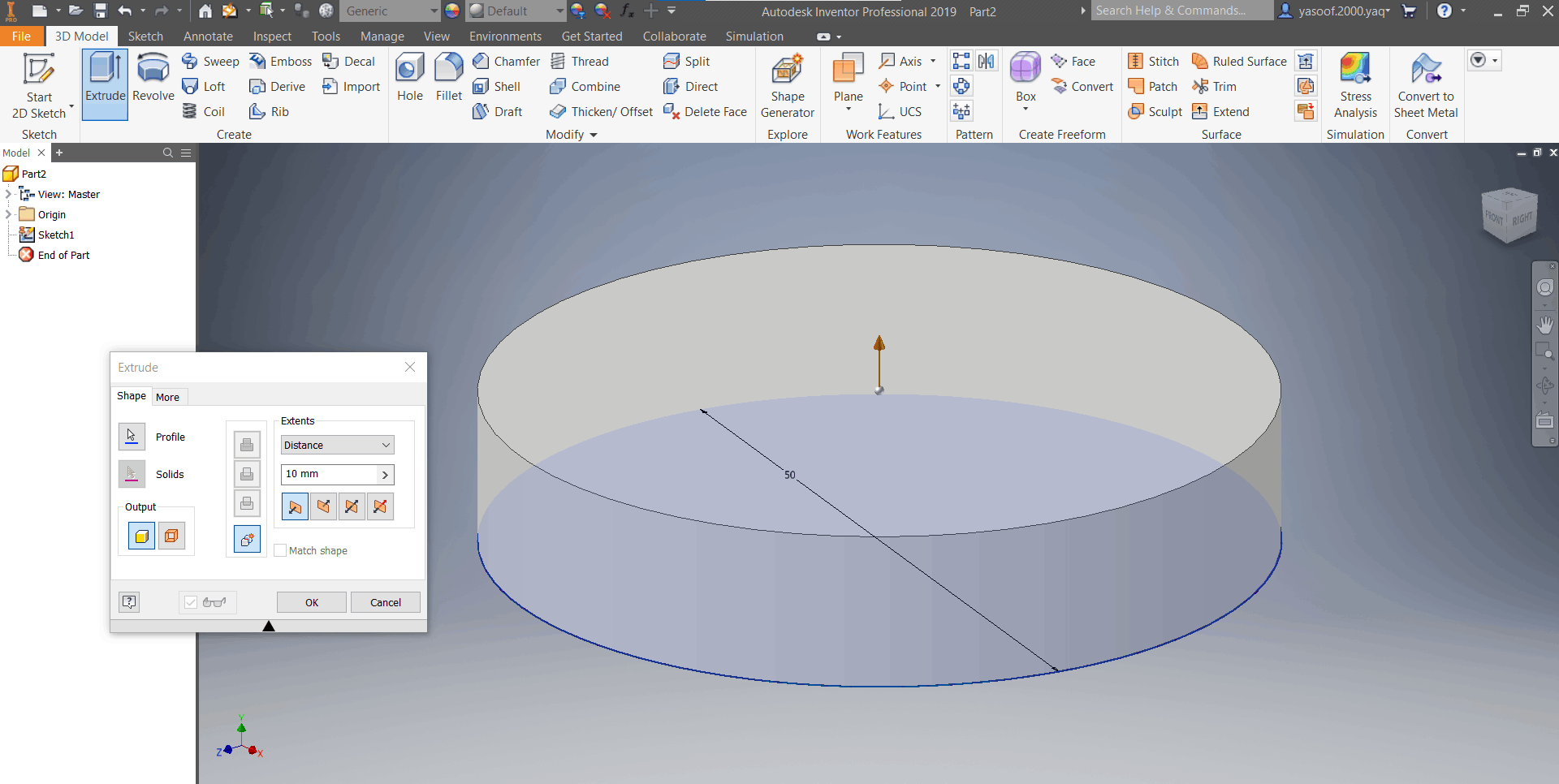
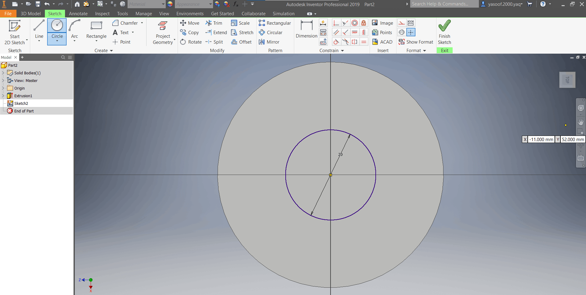
1- Follow the steps 1 and 2 used in 2D model but instead of choosing a random plane, choose a plane which you think is best suited for your design. I chose XZ-plane and drew this circle. 14

2- Make this shape and when you are done click on Finish Sketch. 15

3-When you finish the sketch, you will automatically shift to the 3D model toolbar. Here, you can Extrude your sketch and turn it into a 3D design. Specify the length of your extrusion. I chose 10mm extrusion. 16
4- If you want to create another Extrusion, choose a surface on the extruded design, left click on it, and click on New Sketch. 17

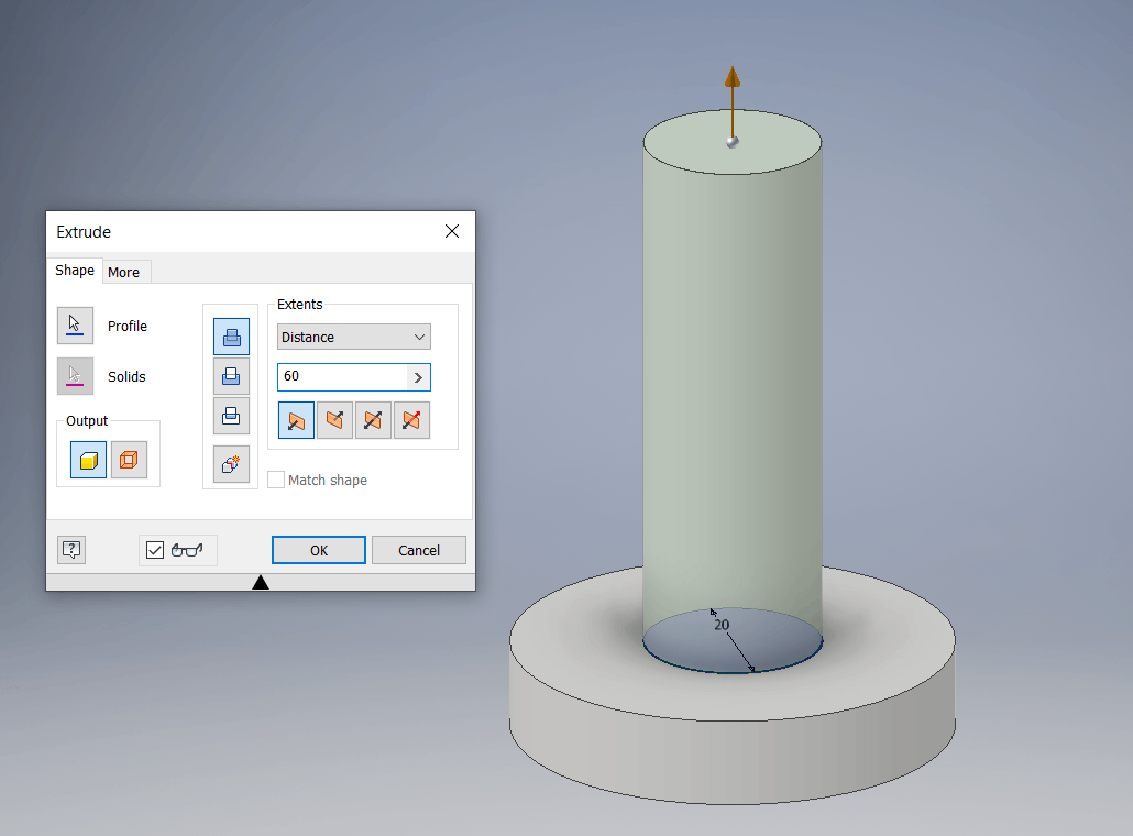
5- Draw another circle, finish the sketch, and make extrusion of 60mm. 18-19
6- Create another sketch on the YZ-plane by selecting it first from the left panel. 20-21
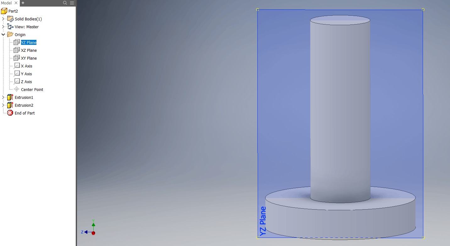
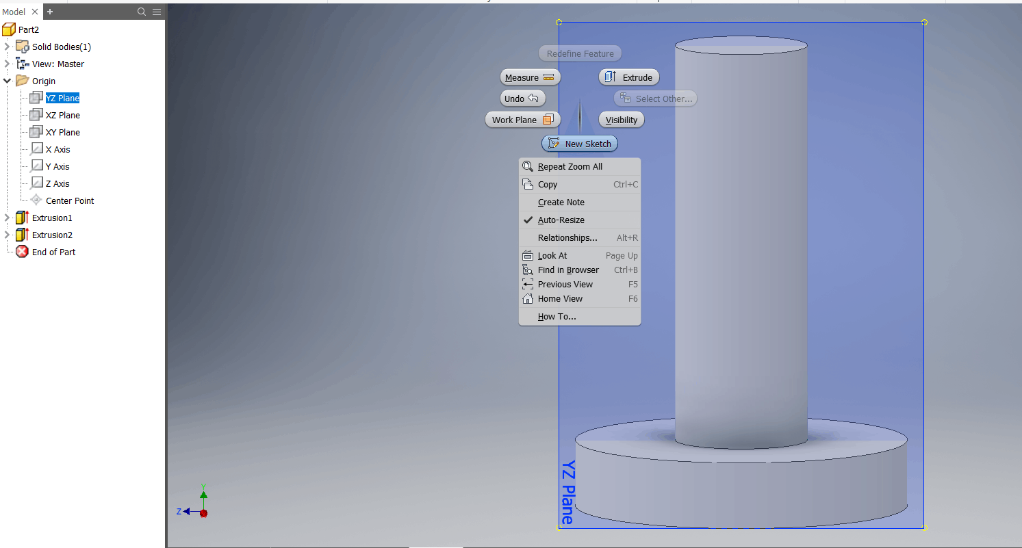
7- Click on f7 to suppress visibility of any part lying in front of the plane. This will allow you to see the sketch you make on the plane that lies in middle of objects. 22

8- Use project geometry to project the visible part shown below. Project geometry is used to project edges, points, or any visible sketch onto the current sketch plane to use it as a reference geometry. 23

9- Draw the shape shown below. 24

10- This time we are going to choose another form of extrusion called revolve which creates an extrusion by revolving the sketch about an axis. 25
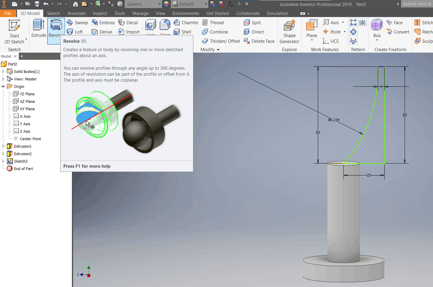
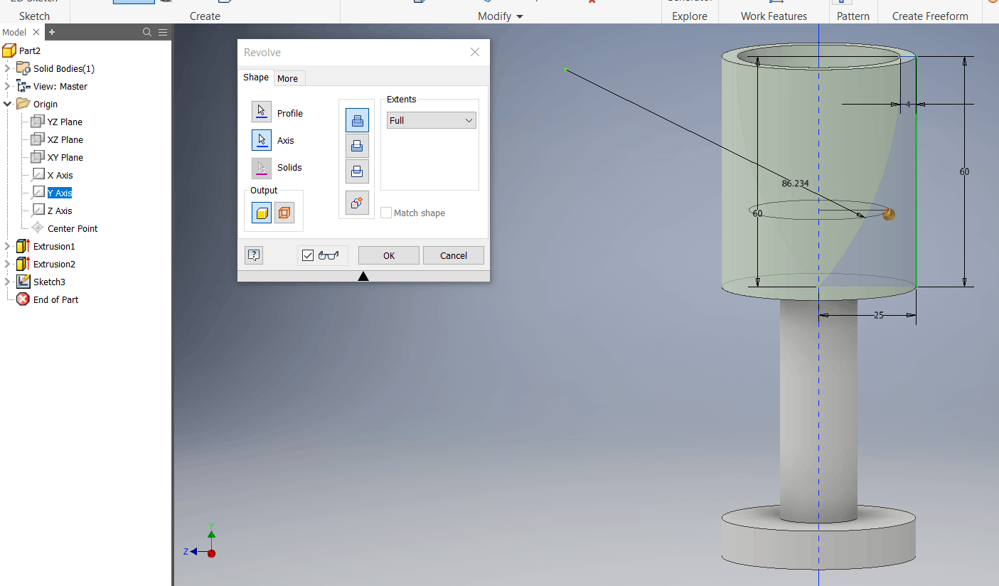
11- Choose the profile to be revolved (i.e., the sketch) and choose Y-axis from the left panel to revolve about it. 26
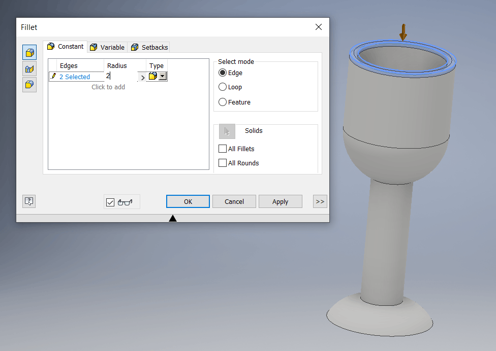
12- Now the cool and easy part is adding fillets. Simply choose the Fillet command, click on the edges to be filleted, and type he radius of the fillet you desire. 27-28-29-30


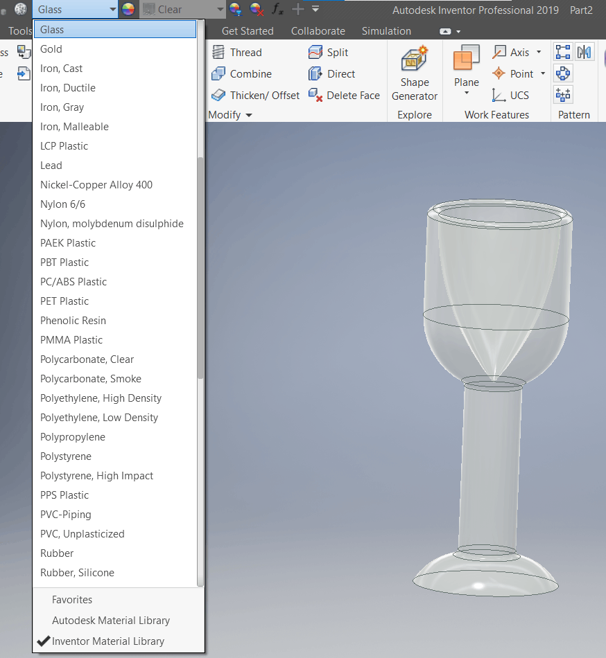
13- Go to materials shown at the top and choose what material you want your part to be. I chose glass in this design. 31
14- Finally save and include your design files.