7. Input & Output device
This week I worked on defining my final project idea and started to getting used to the documentation process.
Research
how physical properties relates to measured results?
Devices for capturing data. An input device is a piece of computer hardware that provides data and control signals to an information processing system such as a computer or other information appliance. Keyboards, mice, scanners, digital cameras, and joysticks are examples of input devices. Between the input and output devices is the computer. The input data is processed and digitized by a computer program. The output device, such as a screen, receives the result. Data bus and other control signals are used by peripherals on the input side or port to transmit information to the CPU.
What is a Breadboard?
A breadboard or protoboard is a board having small holes to connect electronic parts to prototype an electric circuit for an electronic device (robots, detectors, screens, remote controls, etc.). It is used for prototyping because the connections are not permanent. You can easily remove and place components, make different connections, or start over a whole new project. The name breadboard comes from the early days when people used to take a wooden cutting board or a bread board and drive nails or screws to it to make their projects and circuits.

Breadboard can come with different sizes and even different colors.

Inside a breadboard are metal clips. When you press a component into a hole, you are pressing it inside a clip and it grabs onto it.
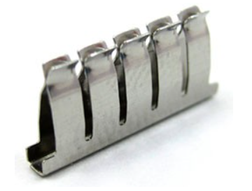
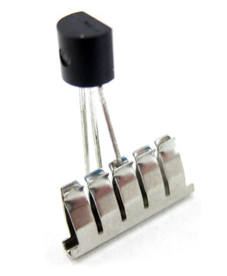
This is how the metal clips are organized in a breadboard. The trench-like gap indicates that the clips on each side are not connected to each other. sometime in bigger breadboards there can be gaps (not like a trench) between the rows of the positive and negative lines.


The numbers and letters on a breadboard are used to indicate the holes just like in Microsoft Excel sheet. For example, this hole is called C12.
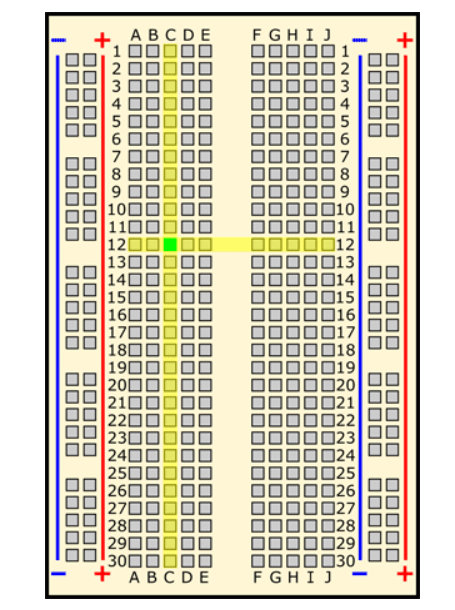
The long strips (called buses) of plus (red) and minus (black) are made to connect to the power supply or ground respectively. However, it is not necessary that you use them, you can even use them the opposite way. They are just to make the circuit more organized. The buses on opposite sides ae not connected to each other but you can do so by connecting the negative strip to the opposite negative strip and do the same for the positive strips. As shown below. 13
Click on this link to learn a lot more about breadboards and the components that can be used in it.
Task
There are different types of tasks varying from easy to extremely hard as shown below:
• Easy Mode: Use the one of the sensors on the Adafruit & try to program to display its results in the serial monitor + to be represented by an LED &/or Buzzer.
• Medium Mode: Use a variable resistor as an input to control either the speed or the direction of the servo motor.
• Hard Mode: Try to create a small automated farming system using the light sensor & the servo motor. Where it’s according to sun day the plant will be given water.
• Extreme Mode: Create a cooling system using a fan, variable resistor, Temperature sensor & an LCD. The idea is to control the fan automatic & manually. You can adjust the fan coolness automatically using the temperature sensor to increase or decrease the fan rotation and display it on the LCD. Or switching the fan to manual mode where you rotate the variable resistor according to how fast you want the fan to go and it should be display on the LCD screen.
The task I did can be considered as an easy mode. I learned how to power an LCD screen, connect it to the microcontroller, give readings based on one of the sensor’s measurements, and give light indication. Pressure and temperature sensor with light indicator and LCD screen:
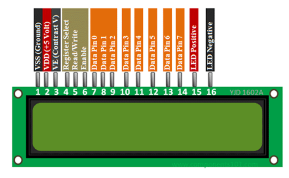
1- Get to know the symbols or names of each pin in LCD screen. Check this link and this link
VSS /GND pin – To be connected to ground (0 Volts).
VCC/VDD pin – This is the power supply for the LCD. From a small search, an LCD can take from 4.7-5.3 Volts. Some say it can take to 5.5 Volts maximum.
VE/Vo (LCD contrast) pin – controls the contrast and brightness of the LCD. You can either connect it directly to the power supply of 5 Volts to get maximum contrast and brightness or connect it to a potentiometer to adjust the contrast and brightness.
RS (Register Select) pin – There are two kinds of data that can be sent to LCD screen:
• Command: any command to control the LCD like set the cursor to a specific coordinate or clear the display. In this case the pin needs to set Low.
• Data: any data you need to display on the LCD. In this case the pin needs to set High.
R/W (Read/Write) pin – If you want to read data from LCD, set the pin to High. If you want to write or send data to LCD, set the pin to Low. Since we are sending data to the LCD (using it as an output device), set the pin to Low (GND).
D0 – D7 (Data bus) pins – These are to transfer data to or from the motherboard or microcontroller to the LCD screen.
A – K (Anode and Cathode) pins – used to power the backlight of the LCD. Connect the Anode to VCC (power supply) and connect the cathode to GND.
An LCD can work on 3.3 Volts but the liquid crystals in the LCD glass may need higher voltage. The LCD we have is of % Volts but you can buy one of 3.3 Volts
You also need to know the LCD screen coordinates so that you refer to them in you code. From image below you can see that the LCD 16x2 includes 16 columns and 2 rows. The columns and rows are indexed from 0. The codes below are used to give output via the LCD with an example:
• lcd.setCursor (0, 0); // move cursor to (0, 0) (column,row)
• lcd.print(“Low”); // print message at (0, 0) Put double quotation marks to print your text.
• lcd.setCursor (0, 1); // move cursor to (0, 1) (column zero, row one/second row)
• lcd.print(temp_event.temperature); // print at (0, 0) Do not put double quotation marks when printing data from a sensor.
• lcd.clear(); // To clear the text. Do this so you do not print text over a previous printed text.

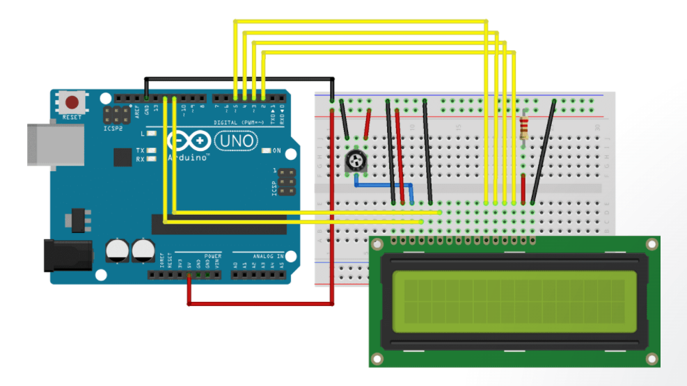
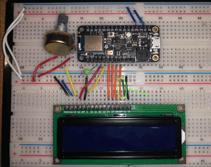
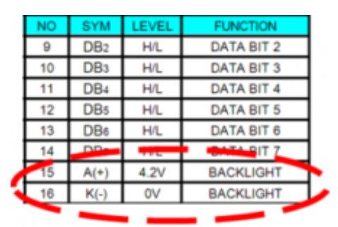
2- Connect the LCD screen using the following Link which has the picture below. However, you can replace the resistor used in pin-15 with a normal wire (the green short wire). This is because pin-15 which is the backlight anode (pin-16 is backlight cathode) needs 4.2-5 Volts (Look at this link) according to the table below. You might need a resistor connected to pin-15 if you are using Arduino since the Arduino is 5 Volts (which might damage the LCD screen). But the Feather sense is just 3.3 Volts. You can also see I chose the Feather sense pins-6,9,10,11,12, and 13 for the LCD screen but you can set any valid pin.
3- Connect your Feather sense to your laptop and try this code below to check if the LCD screen works.
#include <LiquidCrystal.h>

// LCD pins <--> Arduino pins
const int RS = 6, EN = 9, D4 = 10, D5 = 11, D6 = 12, D7 = 13;
LiquidCrystal lcd(RS, EN, D4, D5, D6, D7);

void setup()
{
  lcd.begin(16, 2); // set up number of columns and rows
}

void loop()
{
    lcd.setCursor(0, 0);         // move cursor to   (0, 0)
  lcd.print("Arduino");        // print message at (0, 0)
  lcd.setCursor(2, 1);         // move cursor to   (2, 1)
  lcd.print("GetStarted.com"); // print message at (2, 1)
}
4- Take an LED light and connect it to one of the pins of the Feather sense. I used pin-A5 (look at the picture below step-2) in which you will see in the code used that is shown in step-5.
5- Now follow this code below that will make the following:
• Measure the atmosphere’s temperature and pressure.
• When the temperature is less than 30 C, the light will be off.
• When the temperature is more than 30 C, the light will be on.
• When the temperature is less than 30 C, the LCD screen will show the phrase “low temperature”.
• When the temperature is more than 30 C, the LCD screen will show the phrase “high temperature”.
• The LCD screen will always show the temperature of the atmosphere.
#include <LiquidCrystal.h>
const int RS = 6, EN = 9, D4 = 10, D5 = 11, D6 = 12, D7 = 13;
LiquidCrystal lcd(RS, EN, D4, D5, D6, D7);
int fanPin = 5;

#include <Wire.h>
#include <SPI.h>
#include <Adafruit_BMP280.h>

Adafruit_BMP280 bmp; // use I2C interface
Adafruit_Sensor *bmp_temp = bmp.getTemperatureSensor();
Adafruit_Sensor *bmp_pressure = bmp.getPressureSensor();

void setup() {
  lcd.begin(16, 2);
  pinMode (fanPin, OUTPUT);
  // pinMode (LEDr, OUTPUT);
  //pinMode (LEDb, OUTPUT);

  Serial.begin(9600);
  while ( !Serial ) delay(100);   // wait for native usb
  Serial.println(F("BMP280 Sensor event test"));

  unsigned status;
  //status = bmp.begin(BMP280_ADDRESS_ALT, BMP280_CHIPID);
  status = bmp.begin();
  if (!status) {
    Serial.println(F("Could not find a valid BMP280 sensor, check wiring or "
                     "try a different address!"));
    Serial.print("SensorID was: 0x"); Serial.println(bmp.sensorID(), 16);
    Serial.print("        ID of 0xFF probably means a bad address, a BMP 180 or BMP 085\n");
    Serial.print("   ID of 0x56-0x58 represents a BMP 280,\n");
    Serial.print("        ID of 0x60 represents a BME 280.\n");
    Serial.print("        ID of 0x61 represents a BME 680.\n");
    while (1) delay(10);
  }

  /* Default settings from datasheet. */
  bmp.setSampling(Adafruit_BMP280::MODE_NORMAL,     /* Operating Mode. */
                  Adafruit_BMP280::SAMPLING_X2,     /* Temp. oversampling */
                  Adafruit_BMP280::SAMPLING_X16,    /* Pressure oversampling */
                  Adafruit_BMP280::FILTER_X16,      /* Filtering. */
                  Adafruit_BMP280::STANDBY_MS_500); /* Standby time. */

  bmp_temp->printSensorDetails();
}

void loop() {
  //lcd.setCursor(0, 0);         // move cursor to   (0, 0)
  //lcd.print("Arduino");        // print message at (0, 0)
  //lcd.setCursor(2, 1);         // move cursor to   (2, 1)
  //lcd.print("woohooo!"); // print message at (2, 1)
  int pushed = digitalRead(10);
  sensors_event_t temp_event, pressure_event;
  bmp_temp->getEvent(&temp_event);
  bmp_pressure->getEvent(&pressure_event);

  Serial.print(F("Temperature = "));
  Serial.print(temp_event.temperature);
  Serial.println(" *C");

  Serial.print(F("Pressure = "));
  Serial.print(pressure_event.pressure);
  Serial.println(" hPa");

  Serial.println();
  delay(200);
 digitalWrite(fanPin, LOW);
  if (temp_event.temperature < 30) {
    //digitalWrite(13, HIGH);
    //digitalWrite(12, LOW);
    //digitalWrite(11, LOW);
    lcd.clear();
    lcd.setCursor(0, 0);         // move cursor to   (0, 0)
    lcd.print("Low");        // print message at (0, 0)
    lcd.setCursor (0, 1);         // move cursor to   (0, 0)
    lcd.print("Temperature:");        // print message at (0, 0)
    lcd.setCursor(13, 1);
    lcd.print (temp_event.temperature);
    digitalWrite(fanPin, LOW);
  }
  else if (temp_event.temperature > 30) {
    //digitalWrite(13, HIGH);
    //digitalWrite(12, LOW);
    //digitalWrite(11, LOW);}
    lcd.clear();
    lcd.setCursor(0, 0);         // move cursor to   (0, 0)
    lcd.print("High");        // print message at (0, 0)
    lcd.setCursor(0, 1);         // move cursor to   (0, 0)
    lcd.print("Temperature:");        // print message at (0, 0)
    lcd.setCursor(13, 1);
    lcd.print (temp_event.temperature);
    digitalWrite(fanPin, HIGH);
  }
}
//else if(temp_event.temperature < 24 && temp_event.temperature > 33)
// {digitalWrite(13, LOW);
//digitalWrite(12, LOW);
//digitalWrite(11, HIGH);
5- Verify and upload the code.
6- Take a hero video.
IMG-0044.mp4 from Yousif Al-qattan on Vimeo.
Useful links
- How to Use a Breadboard for Electronics and Circuits
- Liquid Crystal Displays (LCD) with Arduino
- LCD Arduino Tutorial