6. Large format CNC (computer controlled Machining)
This week I worked on defining my final project idea and started to getting used to the documentation process.
Research
Group Assignment
The machine tool used this week was Shopbot PRSalpha. The Shopbot PRSalpha is a gantry-based CNC router. It allows for cutting, drilling, carving, and machining operations. The materials the Shopbot PRSalpha can machine are wood, plastic, aluminum, and many other materials that do not contain iron may be safely milled. It can mill along X-, Y-, and Z- axis. Its transient speed can go as high as 1800 in/min and cutting speed as high as 600 in/min. Click on this link to check the quick-start guide of the Shopbot PRSalpha and PRSstandard.

Safety and Precautions:
Before starting working on any machine, you have to look for the safety and precautions measurements. Below, you will find the general safety and precautions measurements of the Shopbot models PRSalpha and PRSstandard tools.
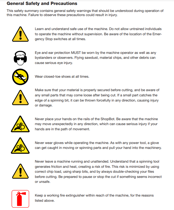
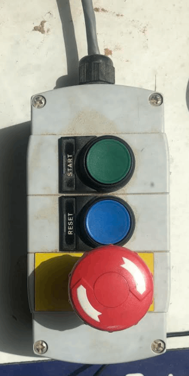
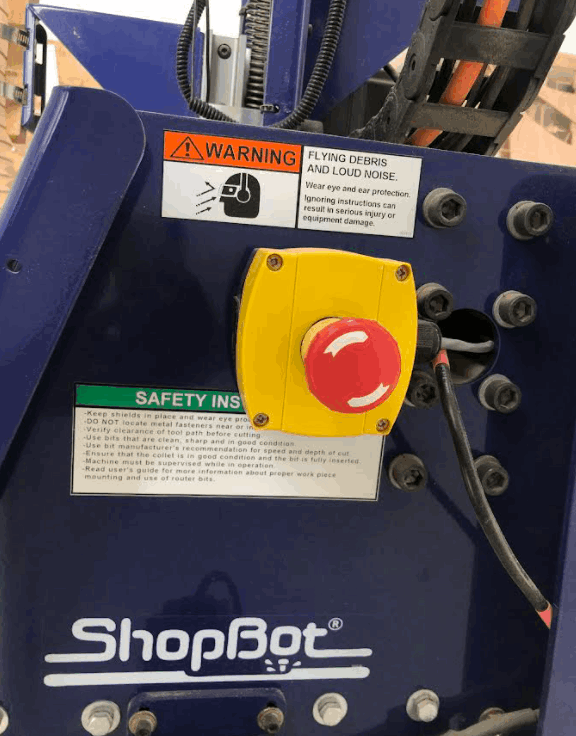
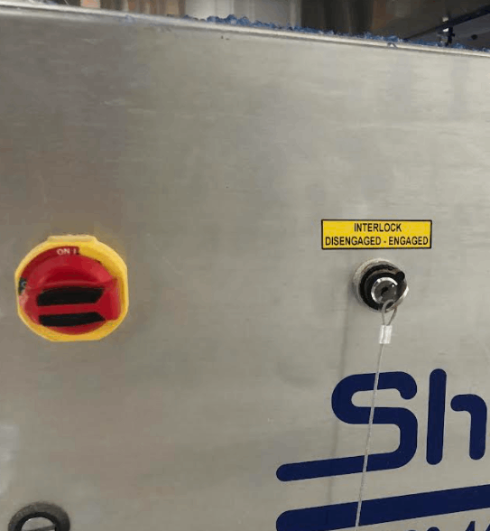
It is also worth mentioning that the PRSalpha has 3 stop buttons the machine and one interlock key.
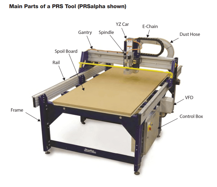
Main parts of a PRS tool
The main parts of a PRS tool are:
• Frame: The structure which provide support and rigidity for the machine to withstand the cutting forces.
• Rail: the track on which the gantry travels. The rail system provides one axis, usually the X-axis.
• Gantry: the bridge-like structure that allows the cutting tool to move and cut in the X- and Y- axis. It is usually driven by two parallel rails. The gantry provides the other axes, usually the Y-axis.
• Spindle: The rotating shaft in which the cutting tool or the workpiece is attached. It is supplied with the power which provides the cutting speed.
• YZ car: provides the motion across the Y- and Z- axis.
• VFD: Variable Frequency Drive. It is a motor controller used to control the speed and torque by controlling the frequency input of the AC motor.
• Control box: It allows the operator to control the machine. It contains the power supply, motor drivers, input and output components, and other electrical parts and their wiring. In the PRSalpha, there is a dual emergency stop disconnect switches. Click on this link to know more about the control box and its wiring.
• Dust hose: Connected to a dust collector to remove dust and material chips produced during the operation.
• Spoil board: also called sacrificial board. It is a disposable board which protects the table or base of the machine. It can also serve as a mounting surface to hold the work. In woodworking, it is usually an MDF board (Medium- Density Fiberboard).
• E-Chain: Energy chain or energy supply chain are cable carriers used to protect and carry the cables that provide the signals and power to the machine parts.
Have a look on the main parts of the PRS tool in the figure below!
Cutting conditions
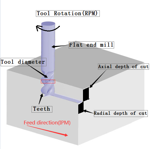
In any machining process, there are 3 main cutting conditions that form 3 dimensions:
1- Cutting speed: The relative motion between the cutting tool and the work. (m/s, mm/sec)
2- Feed: The lateral motion of the cutting tool across the work. (mm)
3- Depth of cut: The motion of the cutting tool required for penetration below the surface of the work. (mm)
Machining has two main operations according to the purpose and cutting conditions:
1- Roughing cuts: It is used to remove large amount of material from the work as fast as possible producing almost the initial shape of the work yet leaving some of the material for finishing operation. General cutting conditions of roughing cuts are:
• High feeds.
• High depths of cut.
• Lower cutting speeds than finishing cuts.
2- Finishing cuts: It is used to produce the final work with the required dimensions, tolerances and surface finish. General cutting conditions of finishing cuts are:
• Low feeds.
• Low depths of cut.
• Higher cutting speeds than roughing cuts.
In milling, the feed is expressed as feed rate (mm/min or in/min).
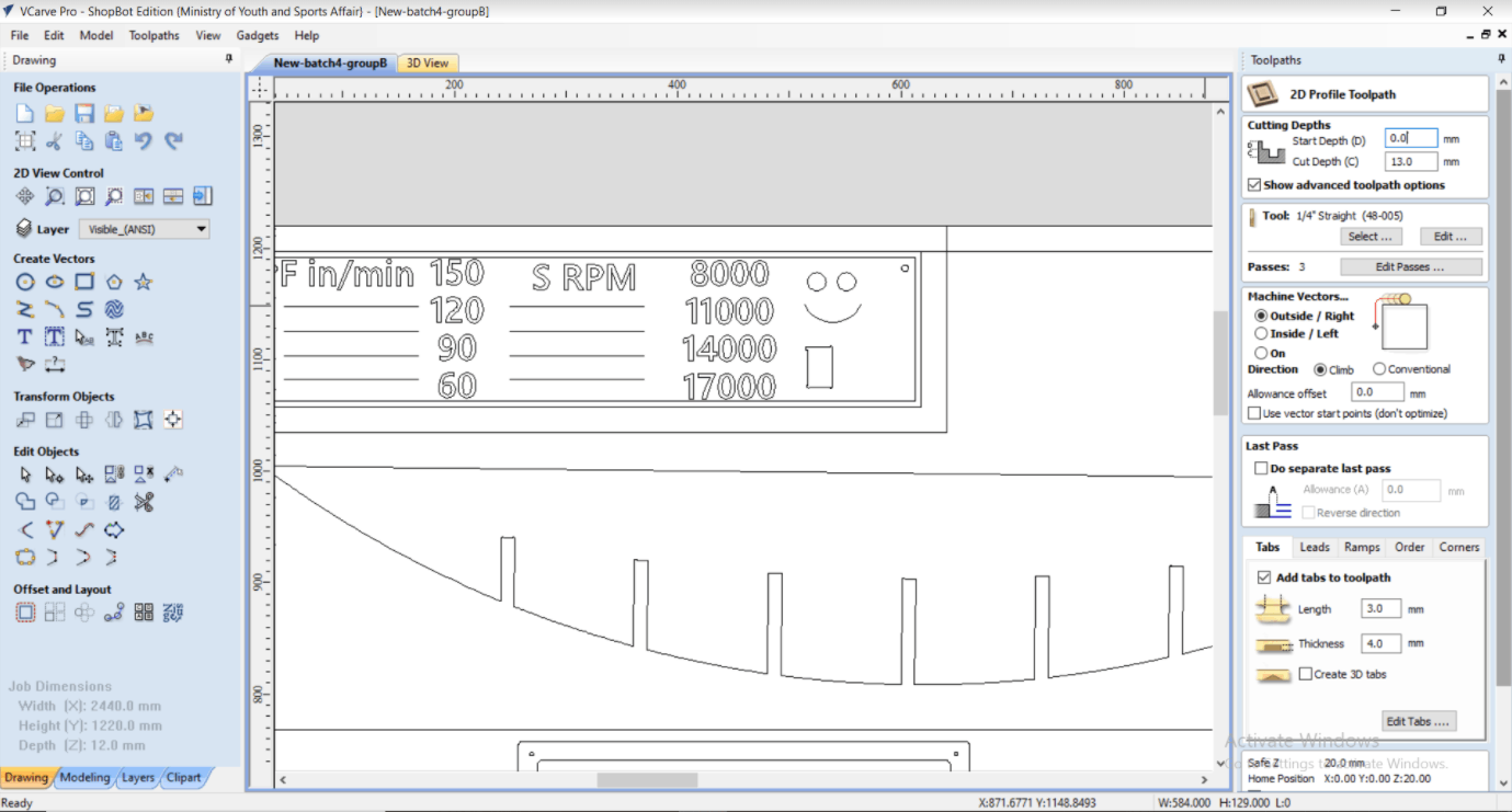
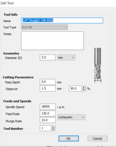
The toolpath is created for a test work via software called VCarve Pro. It is a software for cutting and creating parts on a CNC router and has 2D design tools and inlay 2D toolpath. Click on this link to check the website of VCarve Pro.
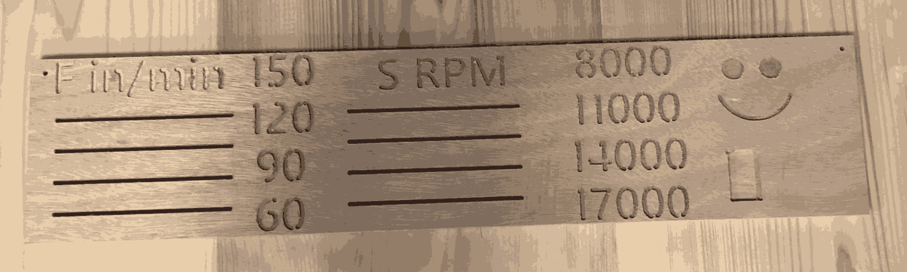
In this video below, you will hear different sounds while cutting with different feeds.
VIDEO-2022-03-21-13-42-21.mp4 from Yousif Al-qattan on Vimeo.
Runout
A runout in rotating parts is when a tool/ part is not perfectly aligned with the main axis of rotation of the rotating toolholder/ tool post (spindle). It is an error or inaccuracy that can lead to surface imperfections.
Individual Assignment
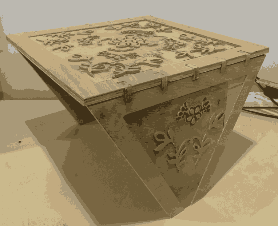
This assignment requires designing, milling, and assembling something big (metric) with an MDF (Medium-Density Fiberboard) plate of size 244cm height x 122cm width x 12mm thickness.
1- Open Autodesk inventor and start making your parts.
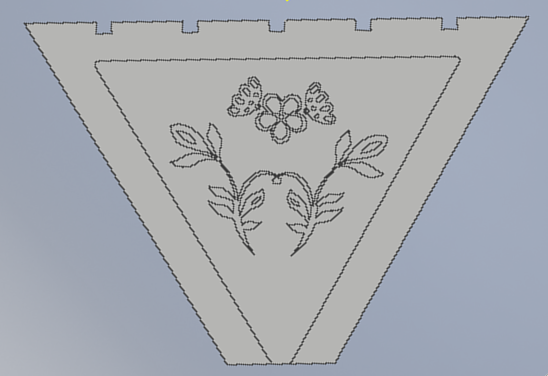
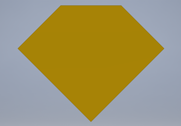
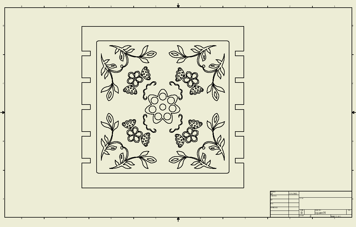
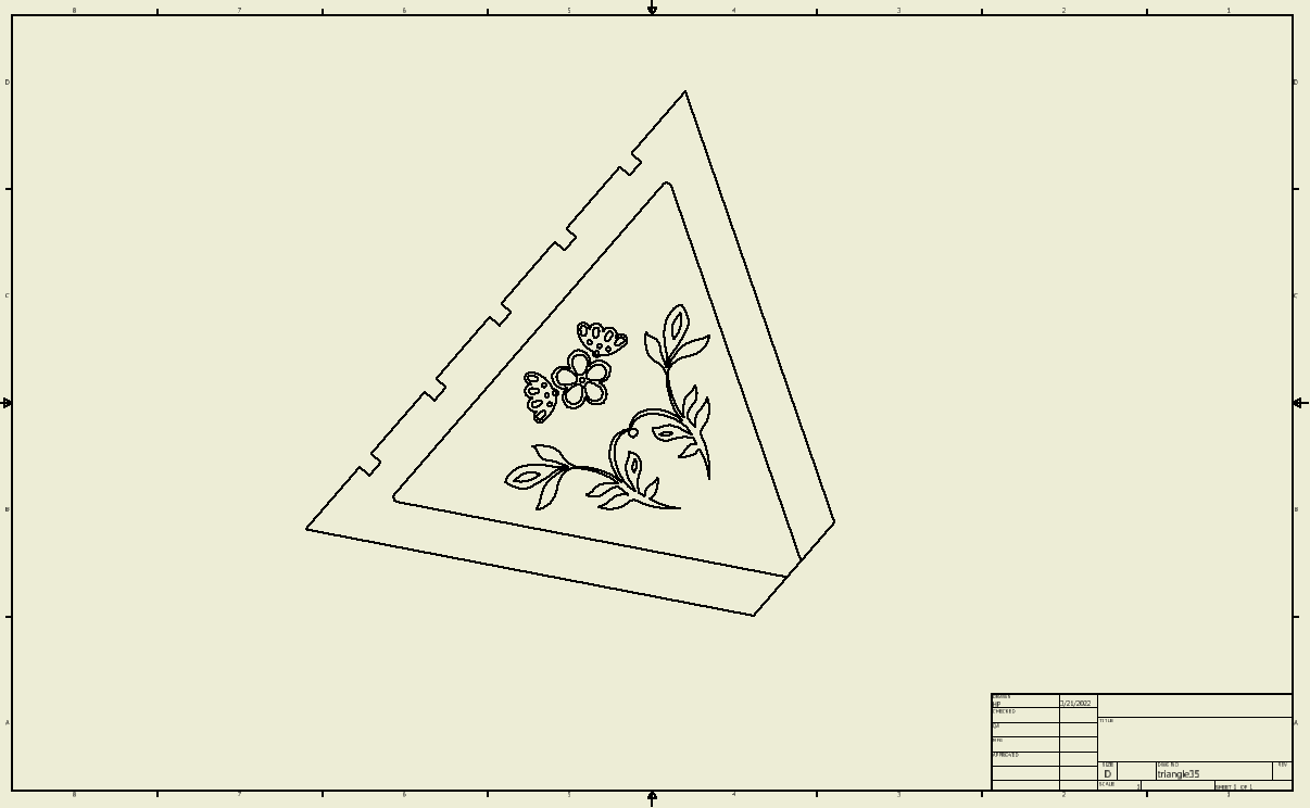
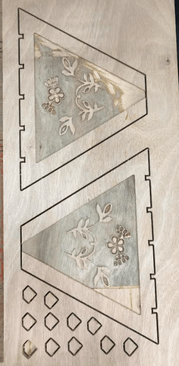
2- The first part was an engraved square and the second was an engraved triangle.
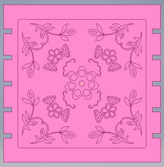
3- A pattern was drawn on the square by uploading an image in a new sketch on the graving and then drawing it using circles, line, and arcs in one corner of the square.

4- Mirror function was used to duplicate the pattern on each corner of the graving.

5- Similar procedure was followed to make the other shapes and also the pattern on the triangle part.
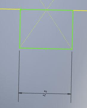
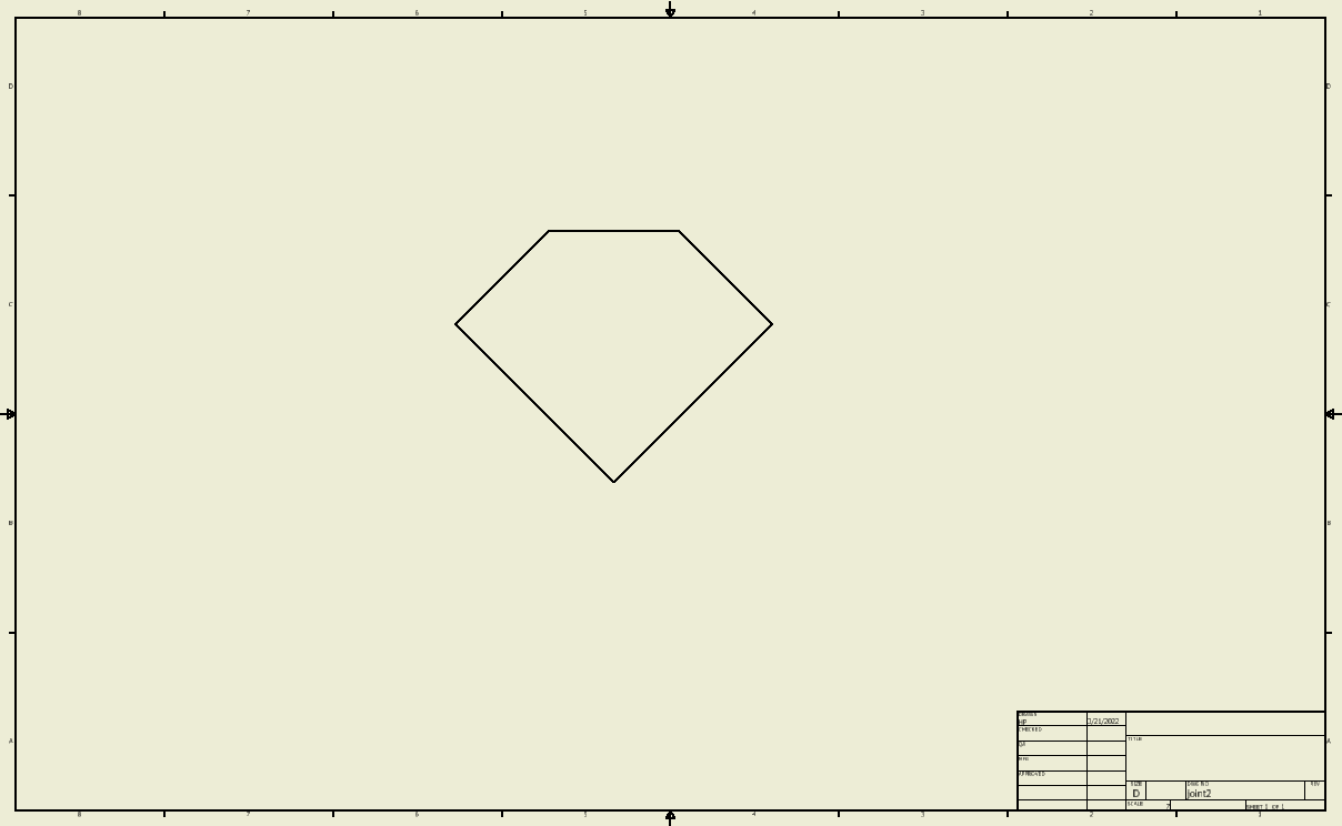
6- Make the joint.
7- Make the cuts in both the square and triangle boards where you want to insert the joint and make the gaps dimensions less by 0.5mm of the thickness of the joint. The joints I made were of 12mm, so I made the gaps having the dimension of 11.5mm. in both the square and triangle boards.
8- Note that the square, triangle, and joint were all extruded to 12 mm as this is the thickness of the MDF board to be milled.
9- Check if the assembly is possible.
10- Open a drawing.
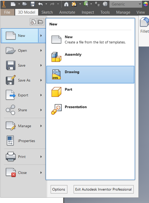
11- Put each part in a single drawing sheet.
12- Save the drawings as dxf. files.
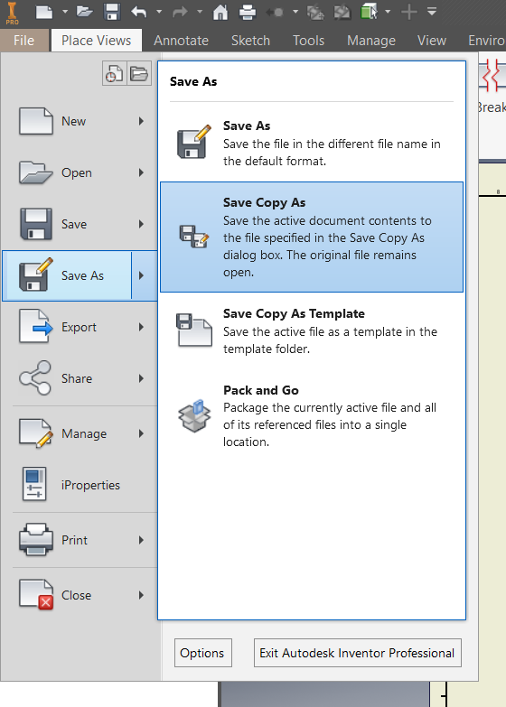
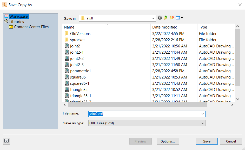
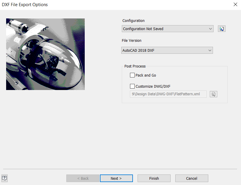
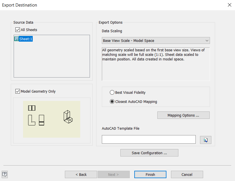
13- Before saving the files click on options showed in the picture above and use the configuration below for the first page and the second page that will appear to you when you click on continue. Then click on finish.
14- Send the files to fablabbh.share@gmail.com.
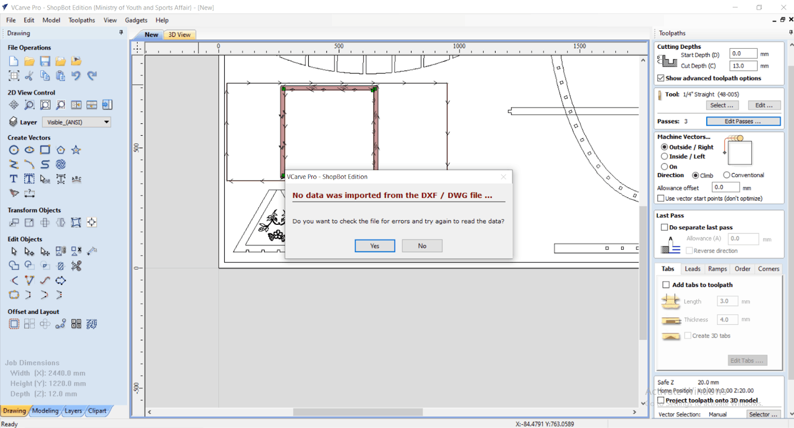
15- Export the file to VCarve Pro software. However, for some reason the file was not opened.
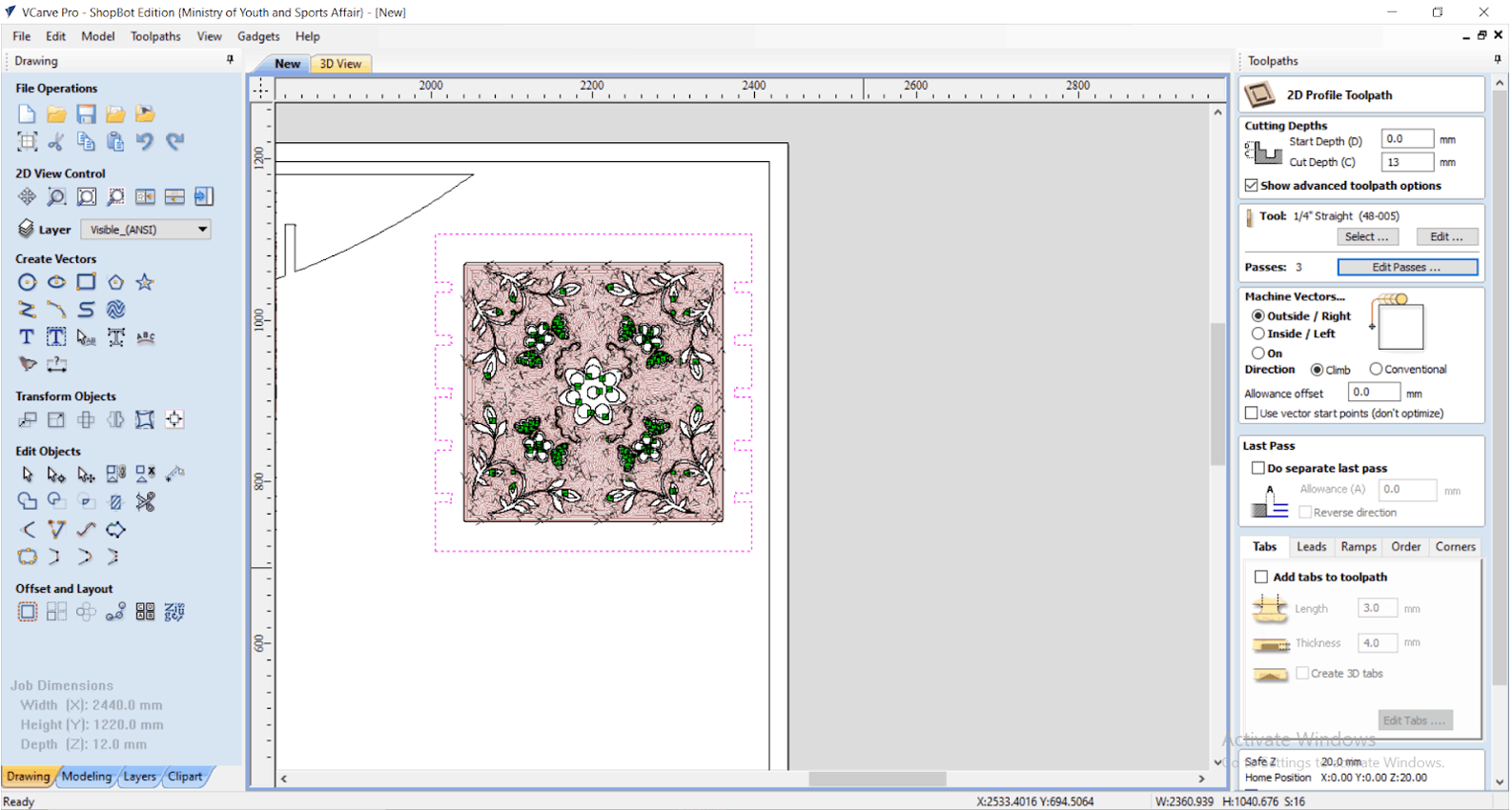
16- Instead, the file was opened in a software called Inkscape. But it needed to be scaled, saved again, and then opened successfully in VCarve Pro software. Click on this link to check Inkscape website.

17- Add the toolpath to the drawing and then start the cutting operation.
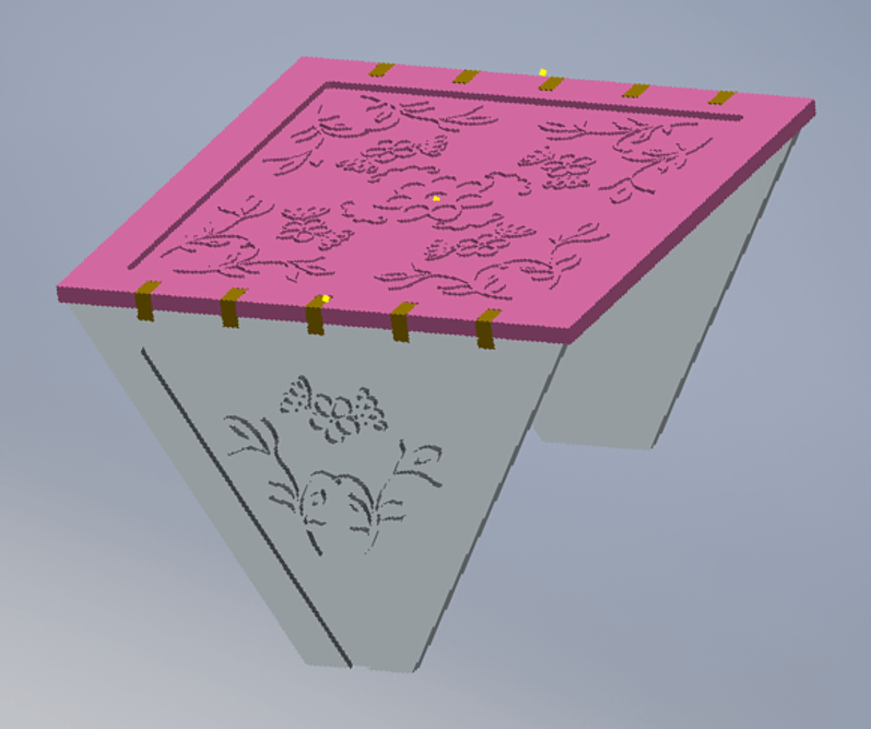
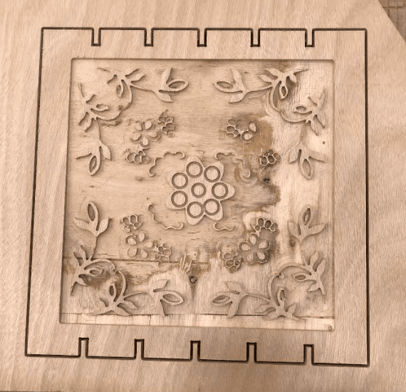
18- The parts of the table were printed successfully. However, the pattern had a lot of defects this can be due to several possible factors like the cheap quality of material (MDF), runout, selecting the wrong parts to be milled in the VCarve Pro software, or others.
19- Another problem raised during the real assembly of the table. The joints were loose and do not fit tightly. After some measurements, the thickness of the plate given did not have 12mm thickness but 11mm. This can be due to mass production error or the plate is not 12mm in thickness everywhere along the plate. The measurements of the joints were all taken based on 12mm thickness plate. However, this was fixed using white wood glue.