4. Embedded programming
Research
Block Coding
Block coding, also called block programming, uses drag-and -drop editor in which programmers can drag and drop blocks (each block represents a bit of code) and snap them together like puzzle pieces in a work area. Block coding provides a fun way of learning coding through visuals instead of the real coding that uses text. It can be used to assemble codes for devices like robots, toys, or home automation. Or it can be used for digital applications like animation and games. Anything that can be coded with text can be coded with blocks.
Goup assignment:
In this link you will find a small article of some microcontrollers of different manufacturers and comparison between them. Also, you will find what different kinds off languages that can be used to program microcontrollers.
Task-1:
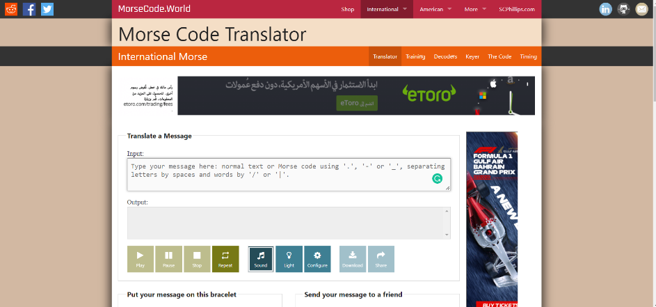
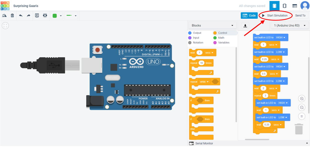
Tinkercad is a free website that helps in building foundational skills for engineering. Tinkercad circuits was used to get started with learning electronics. It is an interactive circuit editor that allows you to code using virtual programming (block coding) with a toolbox of simulate components. Tinkercad circuits allows you to virtually program or simulate Arduino without the need of physical hardware.
The first part of the individual assignment was to blink a morse code in an LED light with Arduino in Tinkercad. You can follow the steps below:
1- Search for a morse code translator in a web search.
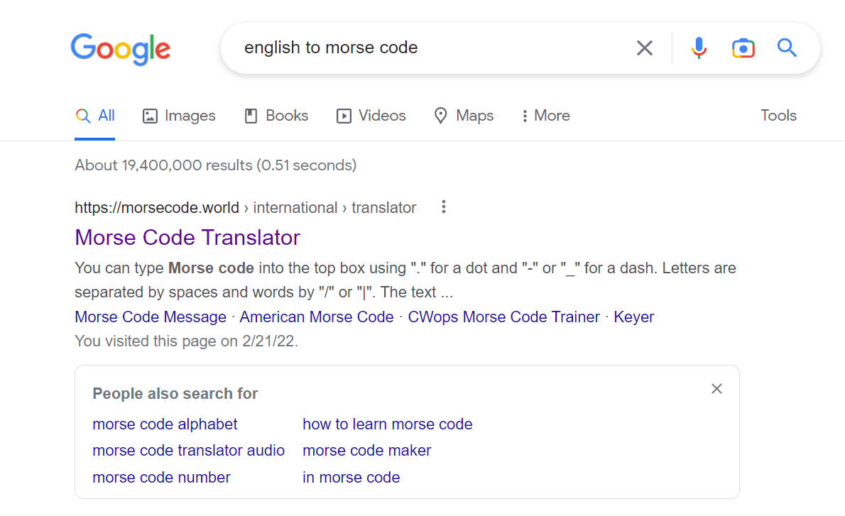
2- Find a website that can translate English to morse code.
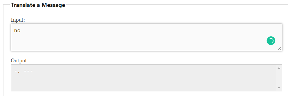
3- Type the word that you want to translate it to morse code.
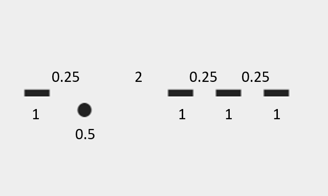
4- Consider the following: for every dit (dot), the LED should luminate for 0.5 second and every dah (dash) means that the light should luminate for 1 second. The space between every dih and dih, dih and dah, or dah and dah in the same letter means the light should be off for 0.25 second. Finally, the space between every alphabetic letter is should be resembled with light being off for 2 seconds.
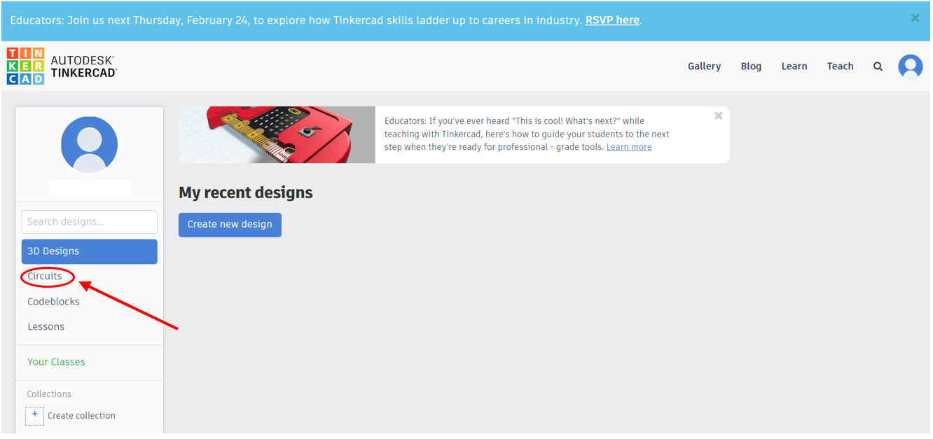
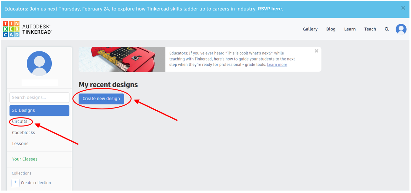
5- Open Tinkercad website, login or register.

6- Select ‘Circuits’. Then, select ‘create new design’.
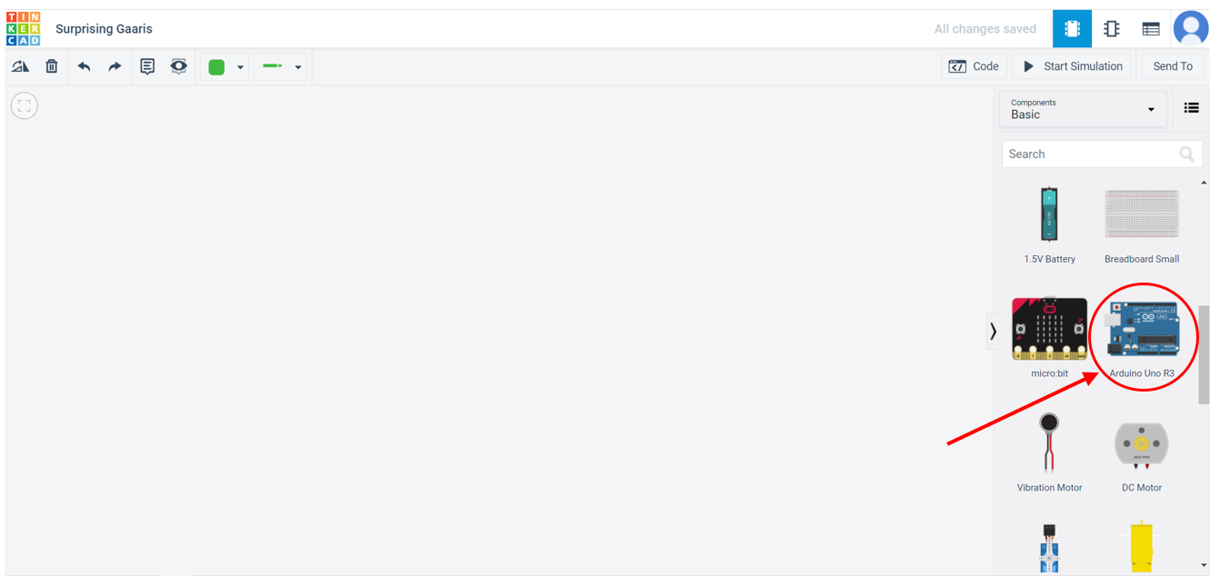
7- Drag the Arduino from the tool box.
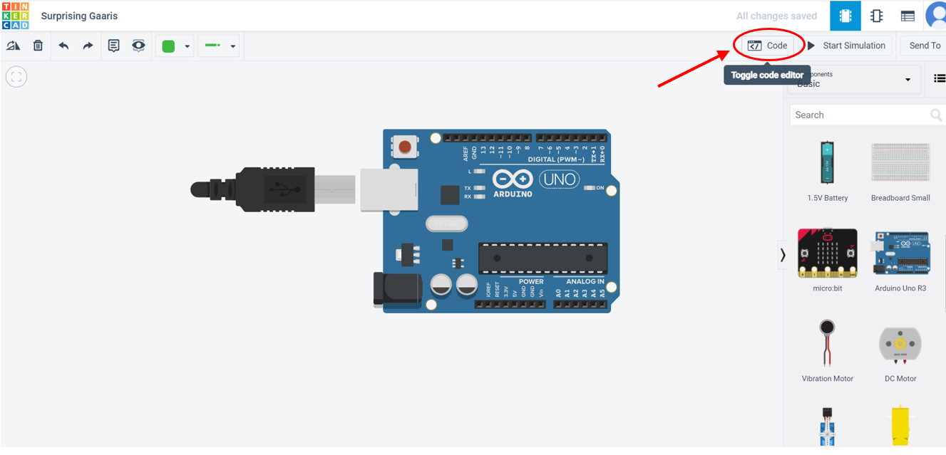
8- Click on ‘code’ to open the code editor.
9- Now you can create your block code by just dragging the blocks you need from the toolbox to the workspace.
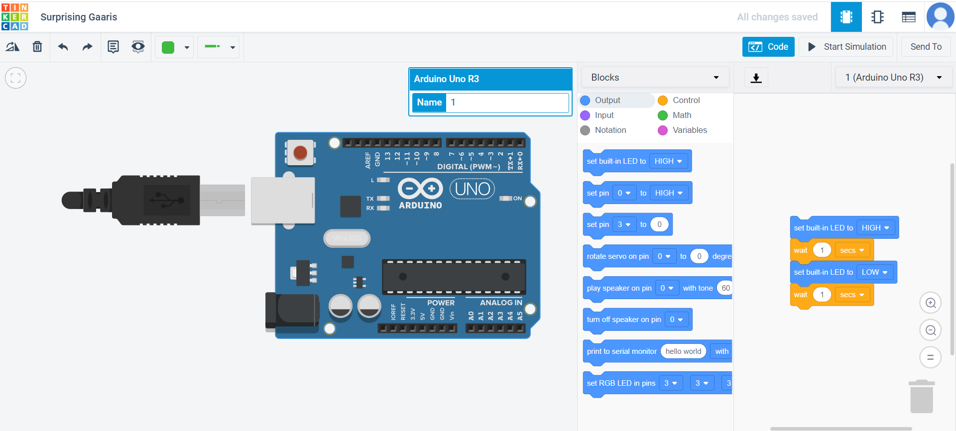
10- The only blocks you need to make blink are: ‘set built-in LED to (High/Low)’ from the output blocks, ‘wait’ from the control blocks, and repeat from the control blocks too. Below is what each block do:
- Set built-in LED to High: turns the LED on.
- Set built-in LED to Low: turns the LED off.
- Wait: is the amount of time the LED will stay on or off.
- Repeat: is used when you have a repeated pattern of blocks.
11- Make a block code in which the virtual Arduino in Tinkercad blinks the morse code you chose.
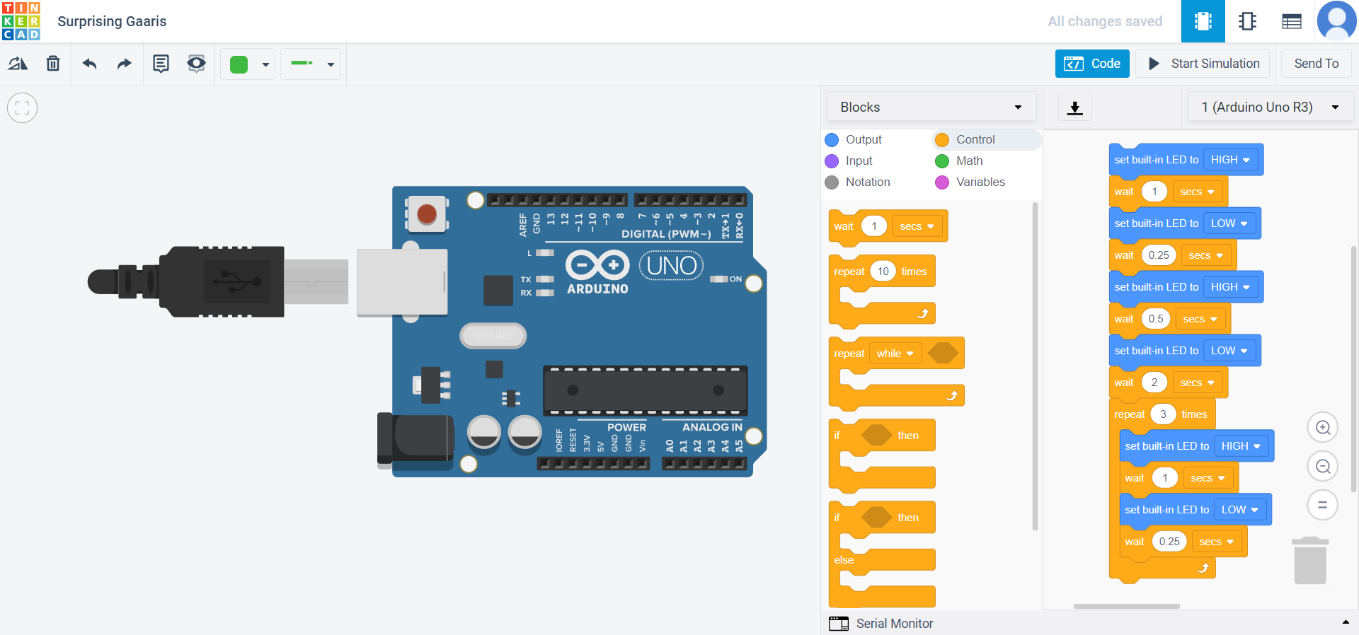
12- Click on ‘start simulation’ to run the block code.
Informations about Adafruit Feather nRF52840:
Microcontroller and QSPI (Quad Serial Peripheral Interface):
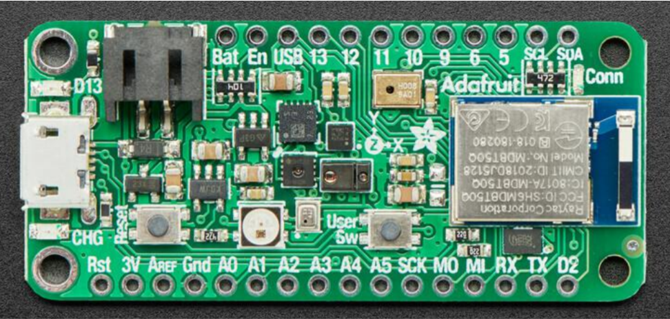
Power pins:
- 3V: This pin is linked to the on-board 3.3V regulator’s output. It may be used to power external sensors at 3.3V.
*LiPo Input (Bat): This is the power supply from the optional LiPo cell linked to the JST PH connection. It has a nominal voltage range of 3.5-4.2V.
*VREG Enable (En): This pin can be set to GND to deactivate the board voltage regulator’s 3.3V output. A pullup resistor is used to set it to high by default.
- USB Power (USB): This is the 4.5-5.2V voltage supply from the USB connection.
Analog inputs (ADC pins):
- (A0-A5) analog inputs: Based on either an internal 0.6V reference or an external supply, the 6 accessible analog inputs (A0… A5) may be set to create 8, 10, or 12-bit data (or 14-bits with over-sampling) at rates up to 200kHz (depending on the bitwidth of the values generated).
The following values are used for Arduino by default:
-
Default voltage range: 0-3.6V (uses the internal 0.6V reference with 1/6 gain)
-
Default resolution: 12-bit (0..4096)
-
Default mV per lsb (assuming 3.6V and 12-bit resolution): 1 LSB = 0.87890625 mV
Two Additional ADC pins are available but preconnected for specific functions:
- It can be used as an optional external analog reference for the internal comparator (COMP) peripheral. AREF is not available for use with the ADC. It can be accessed via PIN_AREF or A7 in code. When using an external AREF, it must equal or be less than VDD, which is usually 3.3 Volts.
PWM Outputs and I2C Pins:
PWM outputs: Using the specialized PWM block, any GPIO pin may be set as a PWM output. Up to 12 PWM channels with independent frequency control in groups of up to four channels can be provided by three PWM modules.
I2C pins: The nRF52840’s I2C pins have 4.7K pullup resistors fitted and are linked to all sensors except the microphone. Any other sensors can be connected as long as there is no I2C address clash.
Sensors:
Gyro + Accel: LSM6DS33 - This sensor is a 6-DoF IMU accelerometer + gyroscope.
Magnetometer: LIS3MDL - Sense the magnetic fields surrounding us.
Light + Gesture + Proximity: APDS9960 - Ambient light, proximity and gesture sensor device. Simple motions can be detected (left to right, right to left, up to down, and down to up are currently supported), the quantity of red, blue, green, and clear light can be returned, and the proximity of an item (how close is an object) to the front of the sensor may be returned.
Humidity: SHT30 - It is a humidity and temperature sensor. It can measure the amount of water in the surrounding air. It has ±2% relative humidity and ±0.5°C accuracy for most uses.
Temp + Pressure: BMP280 - Measures barometric pressure with ±1 hPa (hPa means Hectopascal and 1 Hectopascal is equal to 100 pascal) absolute accuracy, and temperature with ±1.0°C. Because pressure varies with altitude and the pressure measurements are pretty accurate, you may use it as an altimeter with accuracy of ±1 meter.
PDM Microphone sound sensor: MP34DT01-M - PDM sound sensor.
USB and Battery:
USB micro: This USB port is used for programming and/or powering the Feather Sense. it is a normal USB Micro connector.
Battery: There is a 2-pin JST PH connector for a battery . You can power the Feather Sense from any 3V-6V power source, because it has internal regulator and protection diodes. You can also charge LiPoly batteries plugged into this connector using USB power. Always Check that the batteries you are using are the the same as Adafruit polarity. If the batteries have wrong polarity the charging circuitry will be destroyed.
Buttons:
Reset button: This button is next to the USB connector on the left side. Press it once to reset the board. Press it twice quickly to enter the bootloader.
User button: The button on the right is can be used by the bootloader and is controllable by the user too
NeoPixel and Status LEDs:
NeoPixel: The RGB NeoPixel LED is used as a status LED by the bootloader and CircuitPython, but is also controllable using code.
Red status LED: Labeled as D13, is a little red LED. It works as a status LED in the bootloader. But it is also controllable.
Blue status LED: Labeled Conn. is a little blue LED. It works as a connectivity status LED in Arduino. It is also user-controllable in both Arduino aand CircuitPython.
Charge status LED: Labeled CHG, is a little LED belwo the USB connector. It is the charge status LED. It flashes when there is no battery connected. The LED becomes steady amber when a battery is connected and charging.
Please refer to the Datasheet of the specific model of your microcontroller to check the function of other pins, get the codes to control the LEDs and sensors, and a lot of other important information.
Acronyms and Terminology:
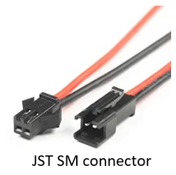
1- What is a JST connector?
“JST Connector” is either shorthand for a connector manufacturer called Japan Solderless Terminal, or a vernacular term for a range of different type of wire to board connectors, which either are, or resemble designs from Japan Solderless Terminal.
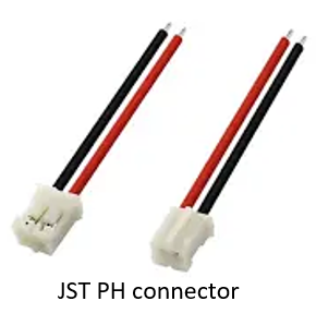
JST PH connector: This is a thin, low-profile 2.0mm pitch connector 8.0mm in height after mounting and 4.5mm in width. It is designed to meet the demand for high-density connection of internal wires to printed circuit boards. It is compact, highly reliable and low in cost.
It is a type of connector designed by JST (Japan Solderless Terminal). It has 2.00mm pitch connector, 8.00mm in height after mounting, and 4.5mm inwidth. It is compact, low in cost, and designed to cope the dense connection of internal wires to printed circuit boards. There are also other types of connectors like the JST SM connector.
2- What is a voltage regulator?
A voltage regulator system is a system designed to automatically maintain a constant voltage. it can be used in myriad applications. One of them is to stabilize the DC voltages used by the processor and other elements. In automobile alternators and central power station generator plants, voltage regulators control the output of the plant. So, you can say it is a circuit that creates and maintains a fixed output voltage, irrespective of changes to the input voltage or load conditions. Voltage regulators (VRs) keep the voltages coming from a power supply within a range that is compatible with the other electrical components.
3- What is comparator?
A comparator is a device which is used to compare two voltages or currents and outputs a digital sign showing which is bigger. It has two analog input terminals and one binary digital output. It is used for digital comparison, meaning it is used for testing whether one number represented by one binary word is greater than, equal, or less than the other number. It is widely used in CPU, microcontroller, combinational, and communication systems.
4- What is a voltage divider?
Voltage dividers are used to get less voltage output from a higher voltage input. So, its output voltage is fraction of the input voltage. The simplest from of a voltage divider is two resisters connected in series.
5- What is an amplifier?
An amplifier, often known as an electrical amplifier or (informally) amp, is a device that can amplify or increase the power of a signal. It’s a two-port electrical circuit that uses power from a power source to increase the amplitude of a signal supplied to its input terminals, resulting in a signal with a correspondingly higher amplitude at the output. Nowadays, most amplifiers use transistore.
6- What does ADC stand for?
Analog-to-digital converters (ADCs, A/Ds, or A-to-Ds) are electronic devices that convert analog signals into digital signals, such as sound picked up by a microphone or light entering a digital camera.
7- What does Vcc stand for?
Means that the supply voltage pin is connected to the transistor’s collector.
8- What does Vee stand for?
Means that the supply voltage pin is connected to the transistor’s emitter.
9- What does Vdd stand for?
Means that the supply voltage pin is connected to the transistor’s drain.
10- What does Vss stand for?
Means that the supply voltage pin is connected to the transistor’s source.
11- What does GND stand for?
The GND (Ground which carries a zero voltage) and is used as a reference point.
12- What is a bit in a computer?
A bit is a short name for binary digit. it is the smallest unit of information or data in a computer. A bit has a singgle binary value which can be either 0 or 1. Half a byte is four bits and is called a nibble.
13- What is QSPI?
(Quad Serial Peripheral Interface) is a serial communication interface.
14- What is analog signal?
An analog signal is a continuous signal in and variable in time and amplitude. In other words, it means one variable is analogous to the other. It has all the values in a given limit of time.
15- What does MOSFET stand for?
Metal Oxide Semiconductor Field Effect Transistor.
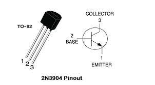
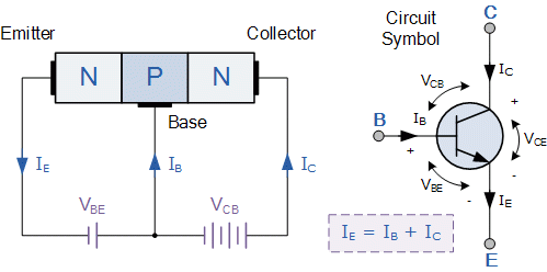
16- What is an emitter in a transistor?
In BJT (Bipolar Junction Transistor) type, it is the the left pin that supply the free electrons (flow of electricity or current).
17- What is a collector in a transistor?
In BJT (Bipolar Junction Transistor) type, it is the the right pin where the free electrons (flow of electricity) are output from. It is where the current leaves the transistor.
18- What is a base in a transistor?
In BJT (Bipolar Junction Transistor) type, it is the the middle pin. The base forms two circuits, the input circuit with the emitter and the output circuit with the collector.
19- What is I2C pin?
I^2C (Inter-Integrated Circuit, eye-squared-C), also known as I2C or IIC is a serial communication protocol. It means that data is transferred one bit a time (bit by bit) along a single wire (the SDA line).
20- What is PWM output?
Pulse width modulation is a modulation technique that is used to digitalize analog input. It is done by generating variable-width (square wave that is switching between on and off) pulses to represent the amplitude of an analog input signal.
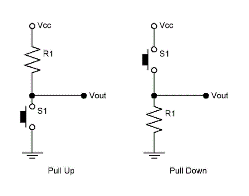
21- What is a pull-up resistor?
A pull-up resistor is used to connect unused pins to the positive supply of the circuit (a resistor connected to the positive supply of the circuit). This is done to keep the given input HIGH.
22- What is a pull-down resistor?
A pull-down resistor is used to connect unused pins to ground (a resistor connected to ground). This is done to keep the given input LOW.
23- What is GPIO pin?
(general-purpose input/output) is an uncommitted digital signal pin on an integrated circuit or electronic circuit board which can be used as an input or output.
24- What is PDM sound sensor?
(Pulse Density Modulation) microphone.
25- What is a bootloader?
A bootloader, boot manager, or bootstrap loader, is a computer program responsible for booting a computer.
Task-2
The aim of this task was to use Arduino IDE (Integrated Development Environment) software which allows you to write codes and upload them to your microcontroller.
1- Click on this link to go to Arduino website.
2- Download Arduino IDE software on your device.
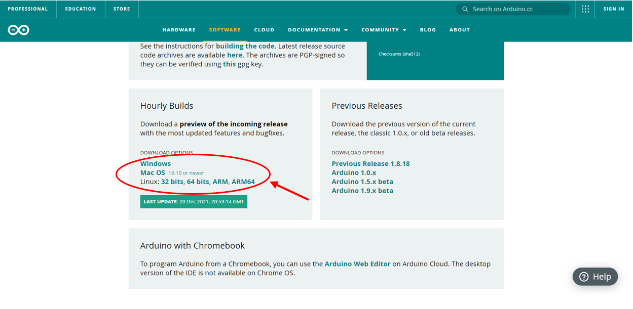
3- Install and run the software.
4- Click on this link and the steps on the website to set up the software.
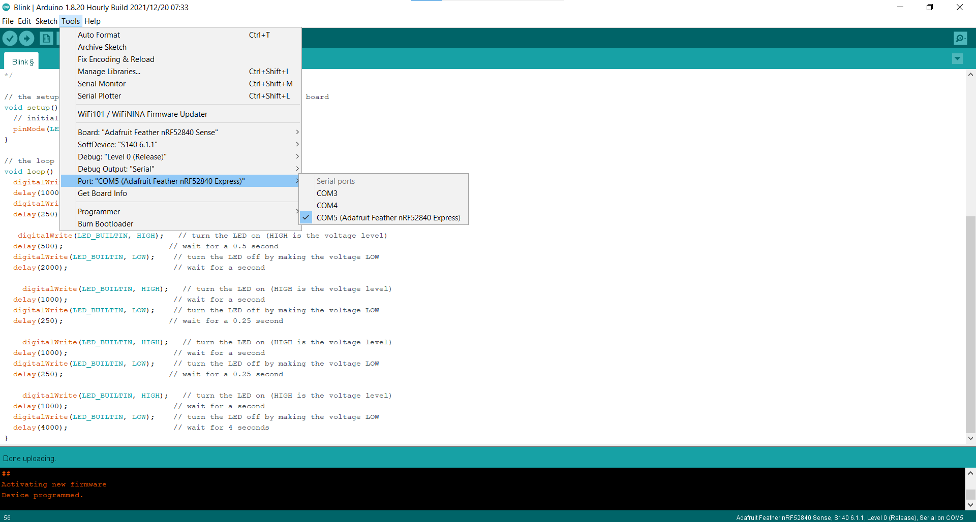
5- Once you are done with the setup using the upper step, connect your Adafruit feather to your device.
6- When your feather starts flashing, click on its restart button twice. It will flash in green.
7- Once it is connected, click on Tools, Port, and select COM% (Adafruit Feather nRF52840 Express).
8- Click on Examples, 01.Basics, then Blink.
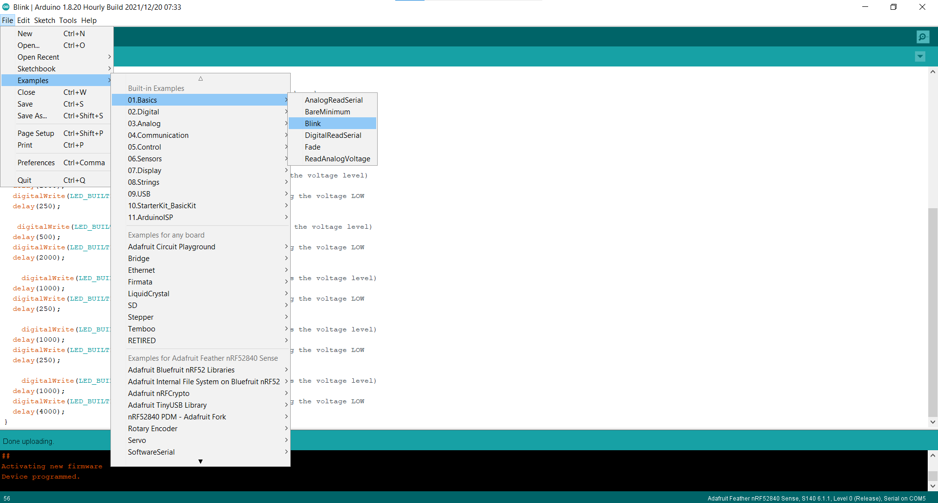
9- A new page will open.
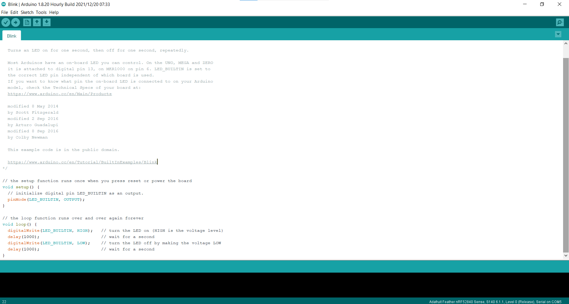
10- Now you can upload this code and this code will turn the LED on for 1 second and turn it off for 1 second. You can do this to check if your feather is working. Note that the software uses milliseconds and not seconds. This is why if you want to have 1 second high for example, you must type 1000.
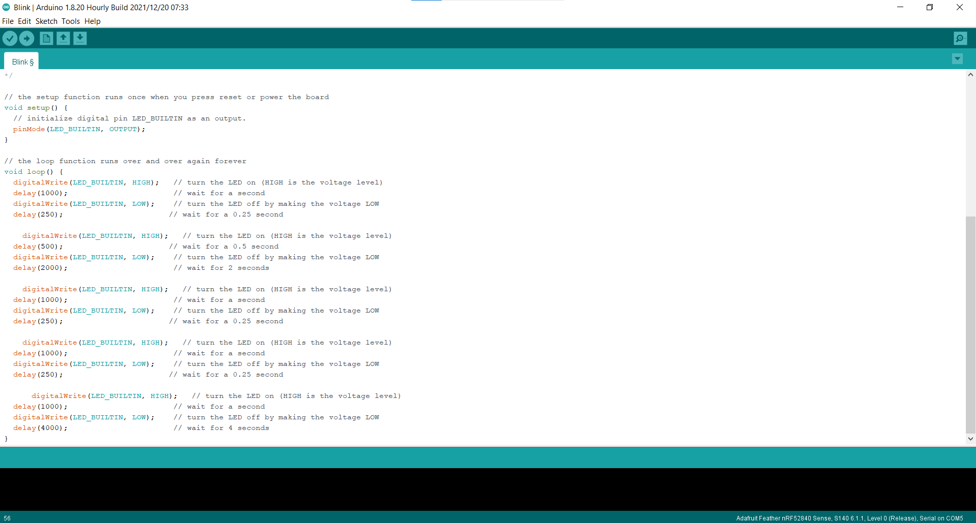
11- However, it is required to make a morse code using the Blink in the feather. So, you can choose the previous morse code you worked in Task-1. Change the code shown in the figure of step 10 to match the morse code you have. The word ‘no’ was used as in Task-1. But, the morse code was ended with 4 seconds (4000 milliseconds)
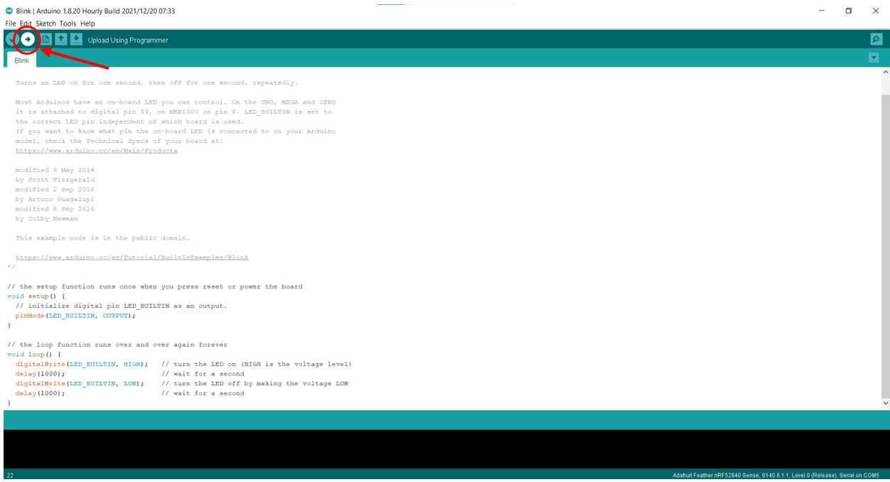
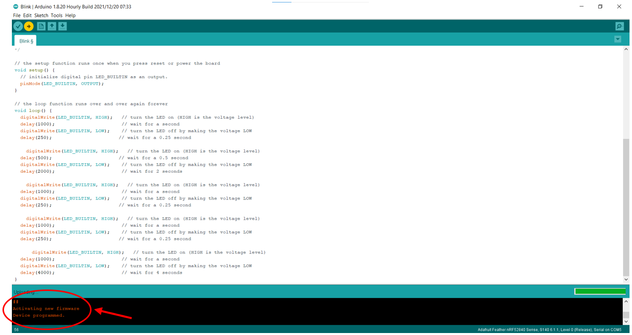
12- Finally upload the file to your feather. Note that sometime your feather can disconnect on its own. So, make sure to repeat step-7 if this occurs.
13- Upload a video showing your Feather blinking your morse code.
Useful links
- Quad SPI, everything you need to know
- Introduction to Bipolar Junction Transistors
- What are the terminals of a transistors
- Circuit playground: M is for MOSFET
- Booting
- Pull up resistor and pull down resistor explained
- Analog signal
- Analog vs Digital: Difference between analog and digital signal
- What is serial communication interface? (SCI)
- Electronic Components Datasheet Search
- Digital Magnitude/Identity Comparator
- What is Voltage Regulator and How Does it Work?
Code Example
Use the three backticks to separate code.
// the setup function runs once when you press reset or power the board
void setup() {
  // initialize digital pin LED_BUILTIN as an output.
  pinMode(LED_BUILTIN, OUTPUT);
}

// the loop function runs over and over again forever
void loop() {
  digitalWrite(LED_BUILTIN, HIGH);   // turn the LED on (HIGH is the voltage level)
  delay(1000);                       // wait for a second
  digitalWrite(LED_BUILTIN, LOW);    // turn the LED off by making the voltage LOW
  delay(250);                       // wait for a 0.25 second

    digitalWrite(LED_BUILTIN, HIGH);   // turn the LED on (HIGH is the voltage level)
  delay(500);                       // wait for a 0.5 second
  digitalWrite(LED_BUILTIN, LOW);    // turn the LED off by making the voltage LOW
  delay(2000);                       // wait for 2 seconds

    digitalWrite(LED_BUILTIN, HIGH);   // turn the LED on (HIGH is the voltage level)
  delay(1000);                       // wait for a second
  digitalWrite(LED_BUILTIN, LOW);    // turn the LED off by making the voltage LOW
  delay(250);                       // wait for a 0.25 second

    digitalWrite(LED_BUILTIN, HIGH);   // turn the LED on (HIGH is the voltage level)
  delay(1000);                       // wait for a second
  digitalWrite(LED_BUILTIN, LOW);    // turn the LED off by making the voltage LOW
  delay(250);                       // wait for a 0.25 second

      digitalWrite(LED_BUILTIN, HIGH);   // turn the LED on (HIGH is the voltage level)
  delay(1000);                       // wait for a second
  digitalWrite(LED_BUILTIN, LOW);    // turn the LED off by making the voltage LOW
  delay(4000);                       // wait for 4 seconds
}
From Vimeo
Sound Waves from George Gally (Radarboy) on Vimeo.