4. Embedded programming
Microcontroller
what is a microcontroler
A microcontroller (MCU for microcontroller unit) is a small computer on a single metal-oxide-semiconductor (MOS) integrated circuit (IC) chip. A microcontroller contains one or more CPUs (processor cores) along with memory and programmable input/output peripherals. Program memory in the form of ferroelectric RAM, NOR flash or OTP ROM is also often included on chip, as well as a small amount of RAM. Microcontrollers are designed for embedded applications, in contrast to the microprocessors used in personal computers or other general purpose applications consisting of various discrete chips.
In modern terminology, a microcontroller is similar to, but less sophisticated than, a system on a chip (SoC). An SoC may include a microcontroller as one of its components, but usually integrates it with advanced peripherals like a graphics processing unit (GPU), a Wi-Fi module, or one or more coprocessors.
Microcontrollers are used in automatically controlled products and devices, such as automobile engine control systems, implantable medical devices, remote controls, office machines, appliances, power tools, toys and other embedded systems. By the reducing size and cost compared to a design that uses a separate microprocessor, memory, and input/output devices, microcontrollers make it economical to digitally control even more devices and processes. Mixed signal microcontrollers are common, integrating analog components needed to control non-digital electronic systems. In the context of the internet of things, microcontrollers are an economical and popular means of data collection, sensing and actuating the physical world as edge devices.
wikipedia
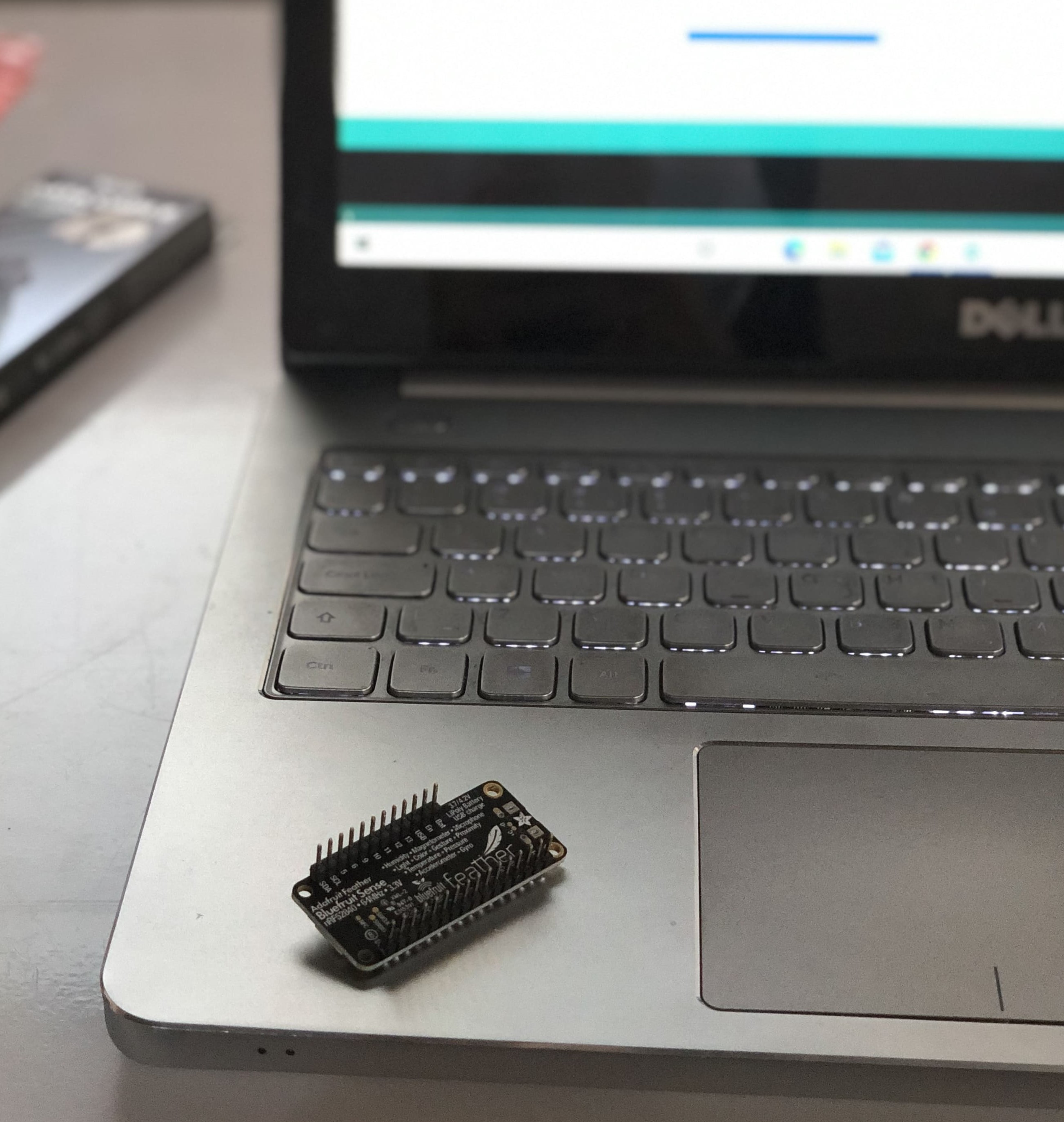
Microcontroler datasheet
By visiting the following link, you can learn everything you need to know about the Adafruit datasheet: adafruit feather datasheet
General features
- ARM Cortex M4F (with HW floating point acceleration) running at 64MHz
- 1MB flash and 256KB SRAM
- Native Open Source USB stack - pre-programmed with UF2 bootloader
- Bluetooth Low Energy compatible 2.4GHz radio (Details available in the nRF528 40 (https://adafru.it/Dvy) product specification)
- FCC / IC / TELEC certified module
- Up to +8dBm output power
- 21 GPIO, 6 x 12-bit ADC pins, up to 12 PWM outputs (3 PWM modules with 4 outputs each)
- Pin 13 red LED for general purpose blinking, Blue LED for general purpose connection status, NeoPixel for colorful feedback
- Power/enable pin
- Measures 2.0” x 0.9” x 0.28” (51mm x 23mm x 7.2mm) without headers soldered in
- Light as a (large?) feather - 6 grams
- 4 mounting holes
- Reset button
- SWD debug pads on bottom of PCB -Works out of the box with all of our Adafruit FeatherWings! (https://adafru.it/vby) (Even the UART-using ones like the GPS FeatherWing)
USB and Battery
- USB Micro - This USB port is used for programming and/or powering the Feather
- Sense. It is a standard USB Micro connector.
- Battery - 2-pin JST PH connector for a battery. Power the Feather Sense from any 3V-6V power source, as it has internal regulator and protection diodes. You can also charge LiPoly batteries plugged into this connector using USB power.
Sensors
In this small board there are various of sensors such as - APDS9960 Proximity, Light, Color, and Gesture Sensor (https://adafru.it/z0d) - BMP280 Temperature and Barometric Pressure/Altitude (https://adafru.it/fIK) - LIS3MDL Magnetometer (https://adafru.it/IfI) - LSM6DS33 Accel/Gyro (https://adafru.it/Iqd) - SHT31 Humidity (https://adafru.it/k6d) - PDM Microphone (https://adafru.it/L-c)
comparassion table between other boards
This is an overview comparassion between arduino uno, raspberry pi and adafruit feather
group assignment
after being divided to 4 groups , our group’s task was to search for the microcontrollers programming languages and compare between them , let’s start with…
What is an embedded programming language?
An embedded programming language is a programming language that developers use in embedded systems. In general, the languages offer low-level access to the device hardware. Developers use several common programming languages for embedded systems.
Some people also call these embedded coding languages. But programming involves much more than coding.
What programming languages are used in embedded systems?
Developers use a variety of programming languages in embedded systems. The most used languages include C, C++, Python, MicroPython, and Java.
Popular programming languages for embedded systems
Programming languages that developers frequently use in embedded systems have some key advantages.
Most languages also have drawbacks. Here are the advantages and limitations of popular embedded
programming languages.
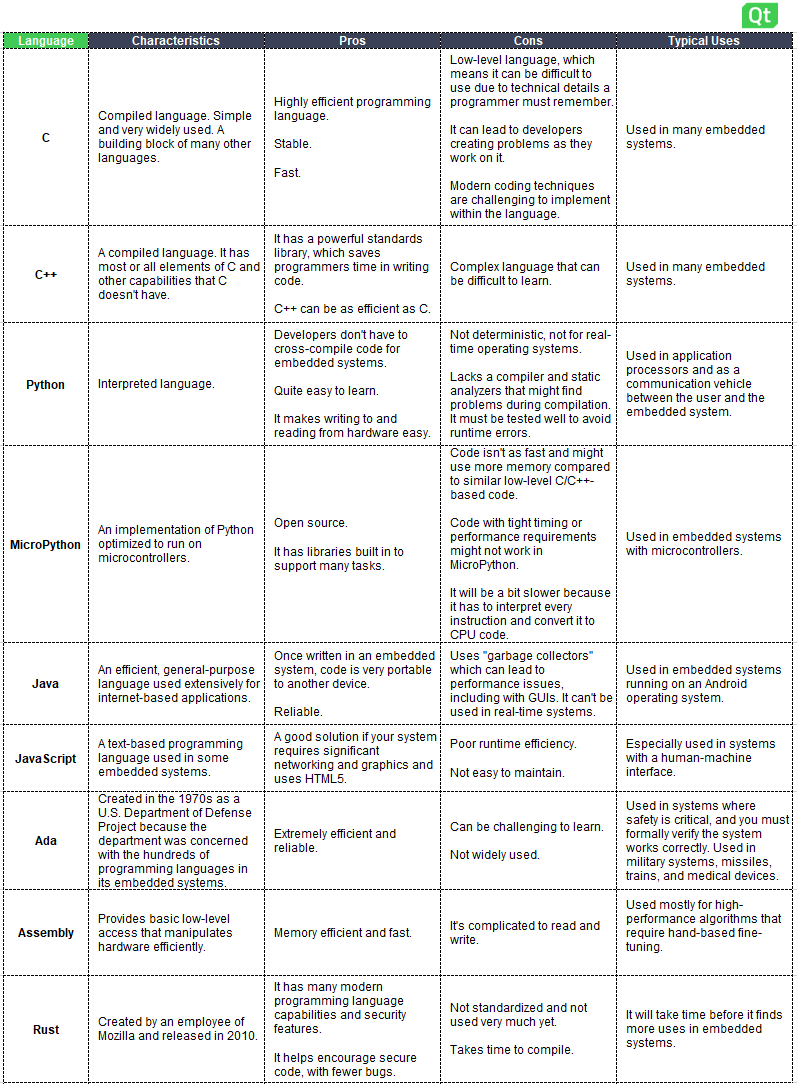
describision of each programming languages
c
- The basics: Developed in the early 1970s, C is a compiled language that serves as a building block of many other languages.
- Pros: C is an efficient and widely used programming language. Industry estimates say 80% of embedded systems use the C programming language.
- Cons: Requires developers to understand and use technical coding techniques that can be complicated.
C++
- The basics: This compiled language has most or all elements of C, but also other capabilities. The language was designed in part for system programming and embedded systems.
- Pros: C++ can be as efficient as using C, but it has a standards library that can save programmers time in writing code.
- Cons: A complex language that can be difficult to learn.
- Expert commentary: “If you look at C++, it has so many capabilities. But there are capabilities in the language that if you don’t use a subset of it, you can really destroy performance in an embedded system. So, there’s that need to recognize that,” explains Jacob Beningo, Embedded Software Consultant and President of Beningo Embedded Group. “You have all of these features, but it’s only a true subset that you can use as an embedded developer. Other features can slow down your code, make it kind of bloated, and just not perform very well.”
Python
- The basics: Developed in the early 1980’s (and named after the British comedy troop Monty Python),Python is a popular programming language. It excels in machine learning, artificial intelligence (AI), and data analytics, but you can use it in many other applications.
- Pros: The language is open source, free to use, and easy to learn, read, and write.
- Cons: This language is not deterministic— not for real-time operating systems (RTOS).
MicroPython
- The basics: This language is a version of Python optimized for microcontrollers.
- Pros: MicroPython is also open source, free to use, and easy to learn.
- Cons: The code isn’t as fast and may use more memory compared to C or C++
- Expert commentary: Beningo says the advantages of MicoPython include “all the libraries, the frameworks, the existing code, and the fact that everybody knows it. It’s easy to learn. I’ve even heard of elementary school students writing Python code.”
Java
- The basics: Java is an efficient, general-purpose language used extensively for internet-based applications. In embedded systems, Java is best for those running on the Android OS.
- Pros: Once written in an embedded system, the code is portable to another device and quite reliable.
- Cons: The language can be complex, leading to performance issues, including those with graphical user interfaces (GUIs). You can’t use Java in real-time systems.
JavaScript
- The basics: JavaScript is a text-based programming language used in some embedded systems.
- Pros: A good option if your system is based on HTML5 and requires significant networking and graphics.
- Cons: Poor runtime efficiency and can be challenging to maintain.
Rust
- The basics: In 2010, a Mozilla employee developed this high-level programming language designed for performance and safety.
- Pros: Rust helps encourage secure code with fewer bugs.
- Cons: Rust takes time to compile. The language isn’t standardized or used much yet.
- Expert commentary: “Rust is still very new. It will take more time until it really penetrates the embedded market on the system level. But its potential is clear, and it should be on every strategic watchlist,” explains Maurice Kalinowski, Product Director for Qt.
Other languages for embedded systems
Developers also use other languages for embedded systems with specific needs. These languages are not common across all embedded systems but are popular in specific cases and perfect for some systems.
Ada
- The basics: In the 1970s, Ada was created as a U.S. Department of Defense project due to its concern about the hundreds of programming languages in its embedded systems.
- Pros: The language is extremely efficient and reliable.
- Cons: Ada can be challenging to learn and isn’t widely used.
Assembly
- The basics: Assembly is a low-level programming language that directly communicates with computer hardware.
- Pros: The language is memory efficient and fast.
- Cons: Assembly can be difficult to read and maintain.
This is summary table to compare between all these programming languages
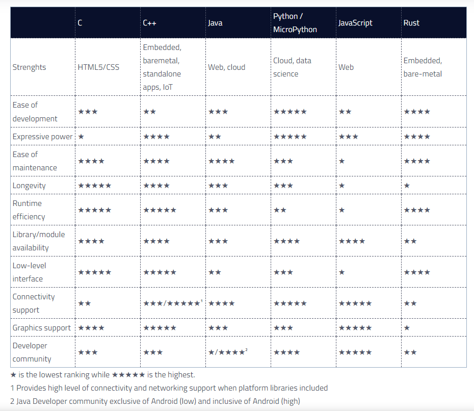
The second’s group assignment was to search about different Types of Microcontrollers Boards and compare between them
click here to view the google docs
Set up the Programming software
- There are a lot of platforms to input your code, and I’m using the Arduino IDE
- Here is the link to the official software’s website click here to download Arduino IDE
- Choose your device type and update version, Mine was Windows 7 and newer
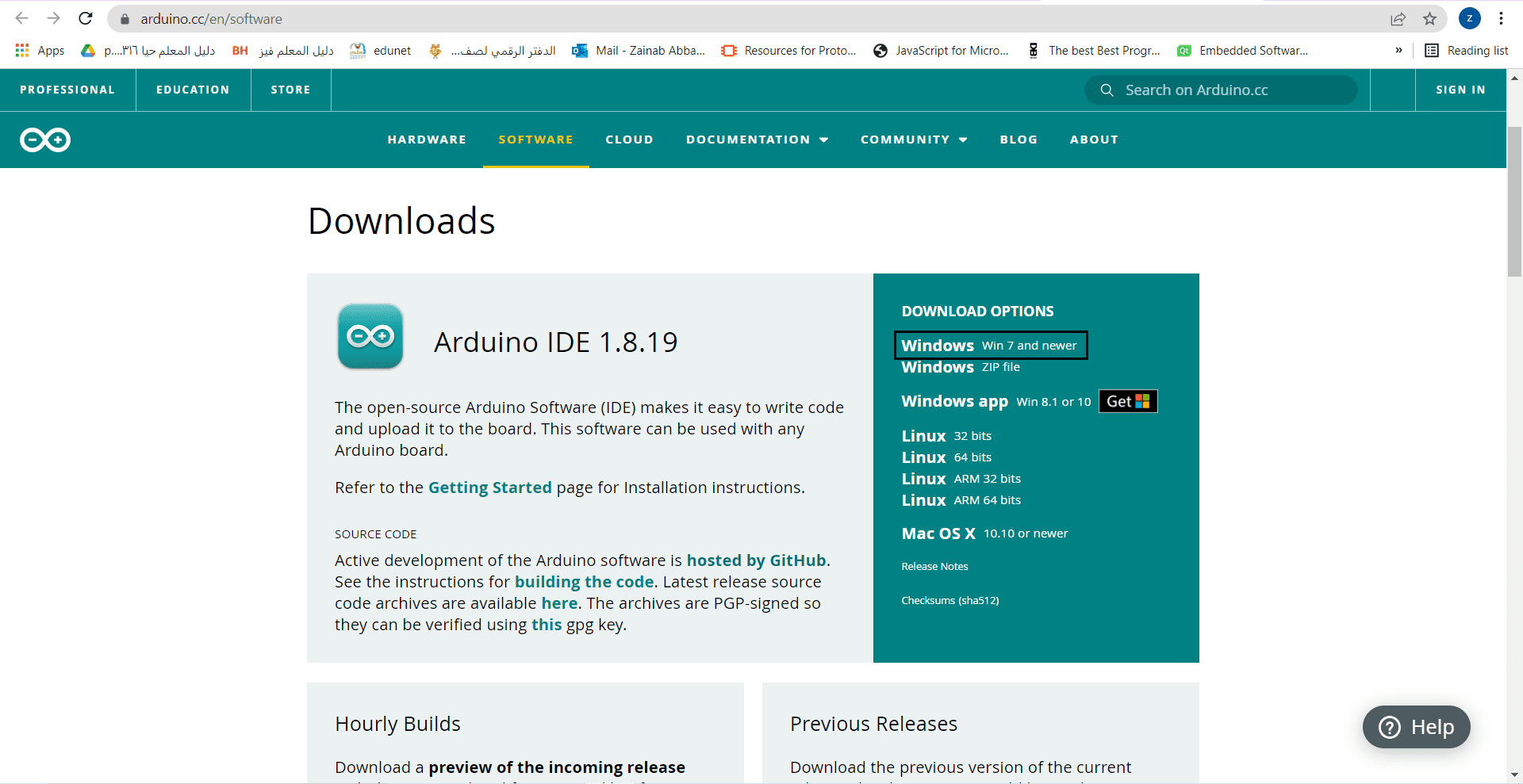
- finish confirmation and setup
-
Finally You will see a blank page , here you should type your codes
-
BSP installation
-
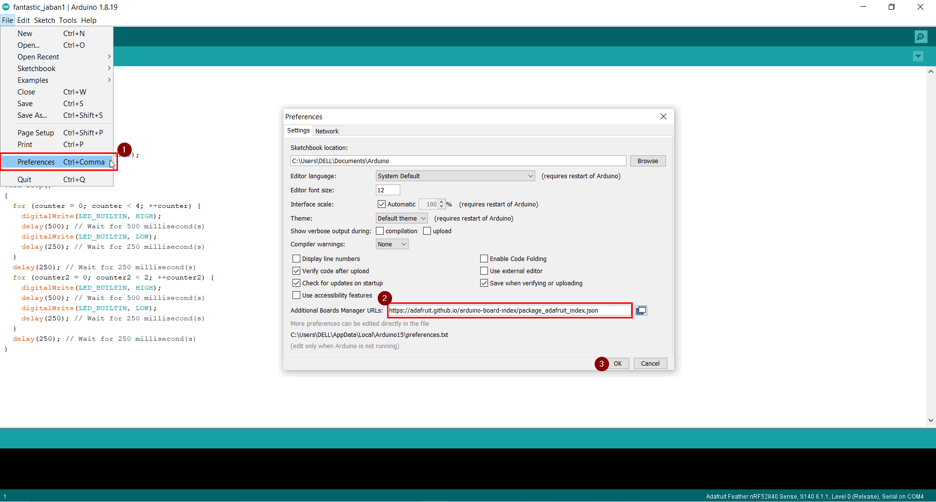
Select Preferences from the menu bar.
-
As a ‘Additional Board Manager URL,’ add https://adafruit.github.io/arduino-board-index/package adafruit index.json (see image below)
-
Restart the Arduino IDE again.
-
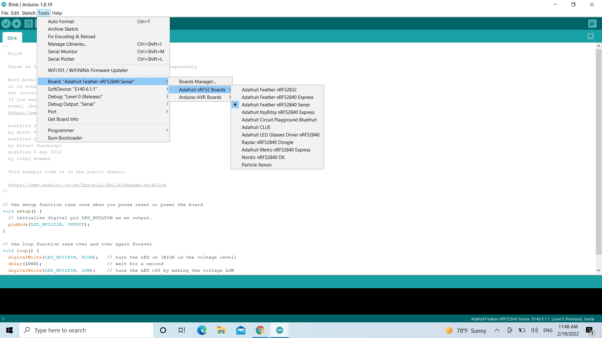
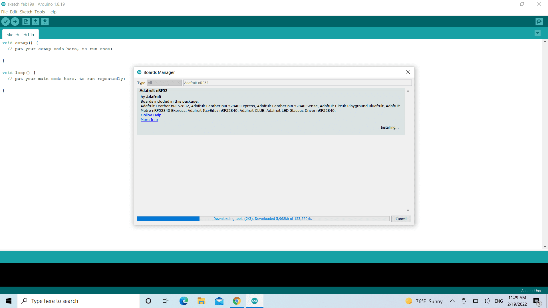
Install ‘Adafruit nRF52 by Adafruit’ using the Boards Manager option from the Tools -> Board menu (see image below)
-
The delay exhibited in the graphic below during the installation stage is normal; please be patient and allow the installation to complete normally:
experiments
blinking
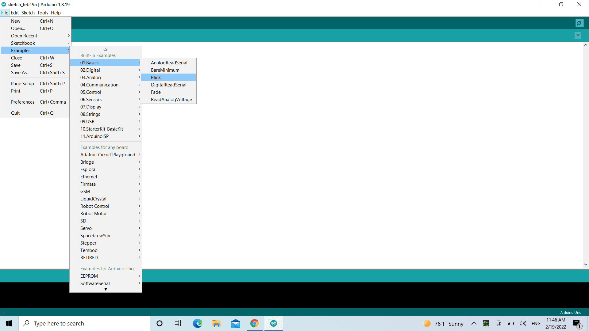
- We start with a simple thing , let’s check the examples found in the software , to program the the built-in light to blink
- In file click examples then basic and you will found the blink
 And these are the codes for the blinking
// the setup function runs once when you press reset or power the board
void setup() {
  // initialize digital pin LED_BUILTIN as an output.
  pinMode(LED_BUILTIN, OUTPUT);
}

// the loop function runs over and over again forever
void loop() {
  digitalWrite(LED_BUILTIN, HIGH);   // turn the LED on (HIGH is the voltage level)
  delay(1000);                       // wait for a second
  digitalWrite(LED_BUILTIN, LOW);    // turn the LED off by making the voltage LOW
  delay(1000);                       // wait for a second
}
the tasks levels
Easy mode: Blink your led but have your blink delay periods be randomized values between 1 second and 5 seconds Medium mode: pre code your microcontroller to send a Morse code 1 word message and challenge a friend, family member, your colleagues or your instructor to figure it out. dot = 0.5 second light on. dash=1 second light on. gap between dots and dashes=0.5 second light off. gap between letters=2 second light off
Hard mode: you select the duration of the light being on and off while the program is running by entering it in the serial monitor. Write a code that takes the data from the serial monitor and delays by that amount of time.
Easy mode
The task is to Blink your led but have your blink delay periods be randomized values
between 1 second and 5 seconds
1. To pick randomized value .
2. Selct math blocks (green ) and choose (pick random block ) and fill your range of numbers.
3. Then insert it into the value time of wating
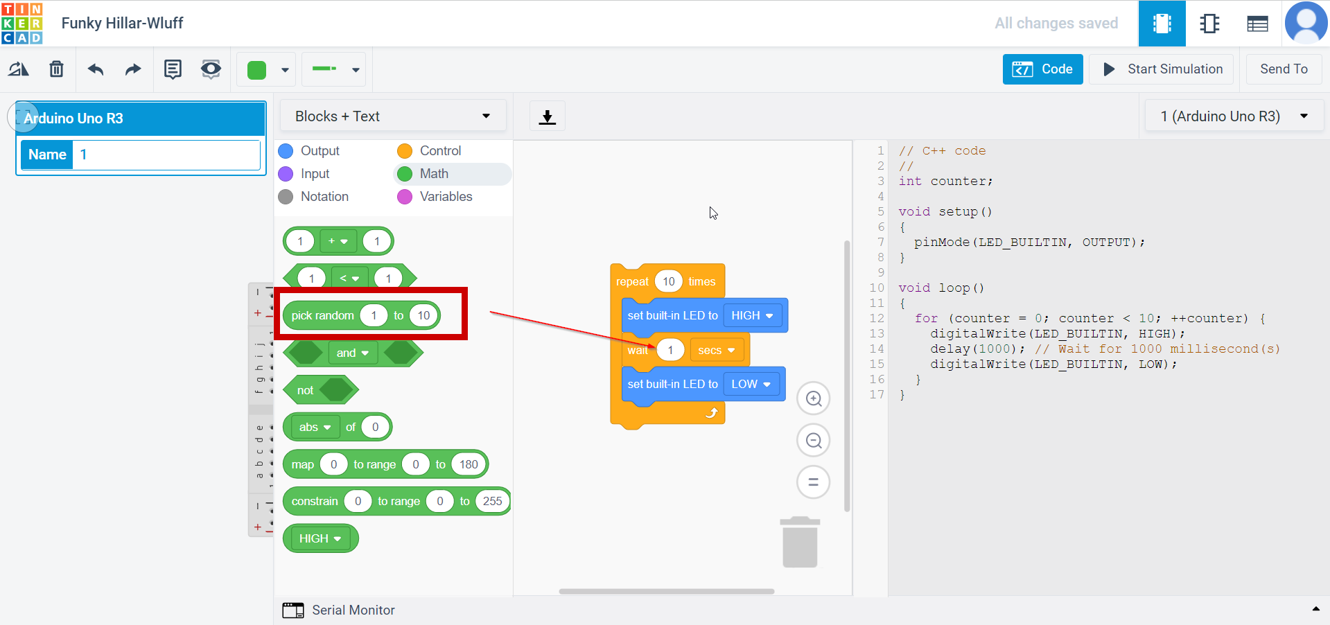 .
.
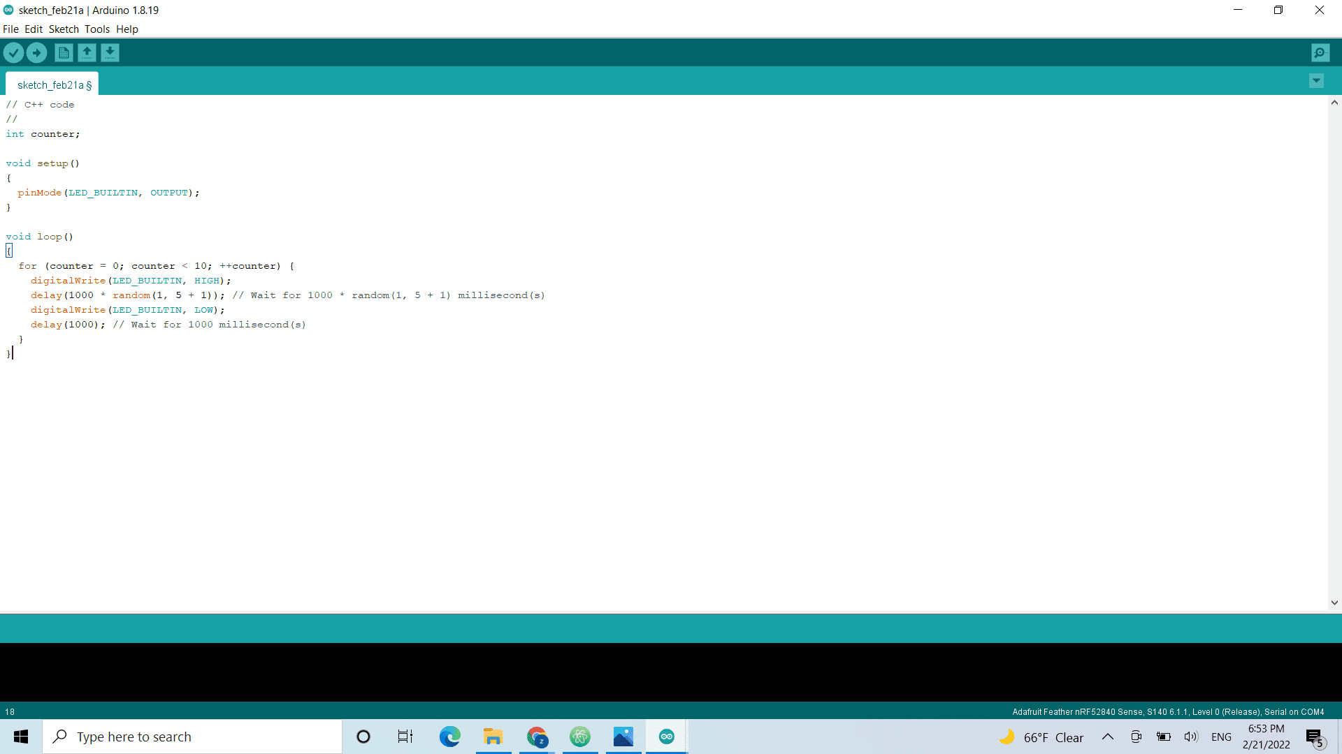
The final blocks and should look like this
// C++ code
//
int counter;

void setup()
{
  pinMode(LED_BUILTIN, OUTPUT);
}

void loop()
{
  for (counter = 0; counter < 5; ++counter) {
    digitalWrite(LED_BUILTIN, HIGH);
    delay(1000 * random(1, 5 + 1)); // Wait for 1000 * random(1, 5 + 1) millisecond(s)
    digitalWrite(LED_BUILTIN, LOW);
    delay(1000 * random(1, 5 + 1)); // Wait for 1000 * random(1, 5 + 1) millisecond(s)
  }
}
Medium mode
Morse codes
Morse code is a method used in telecommunication to encode text characters as standardized sequences of two different signal durations, called dots and dashes, or dits and dahs. Morse code is named after Samuel Morse, one of the inventors of the telegraph.
There are lots of website to convert the word/sentence into morce code , The webisite in the link is the one I used Morse code translator
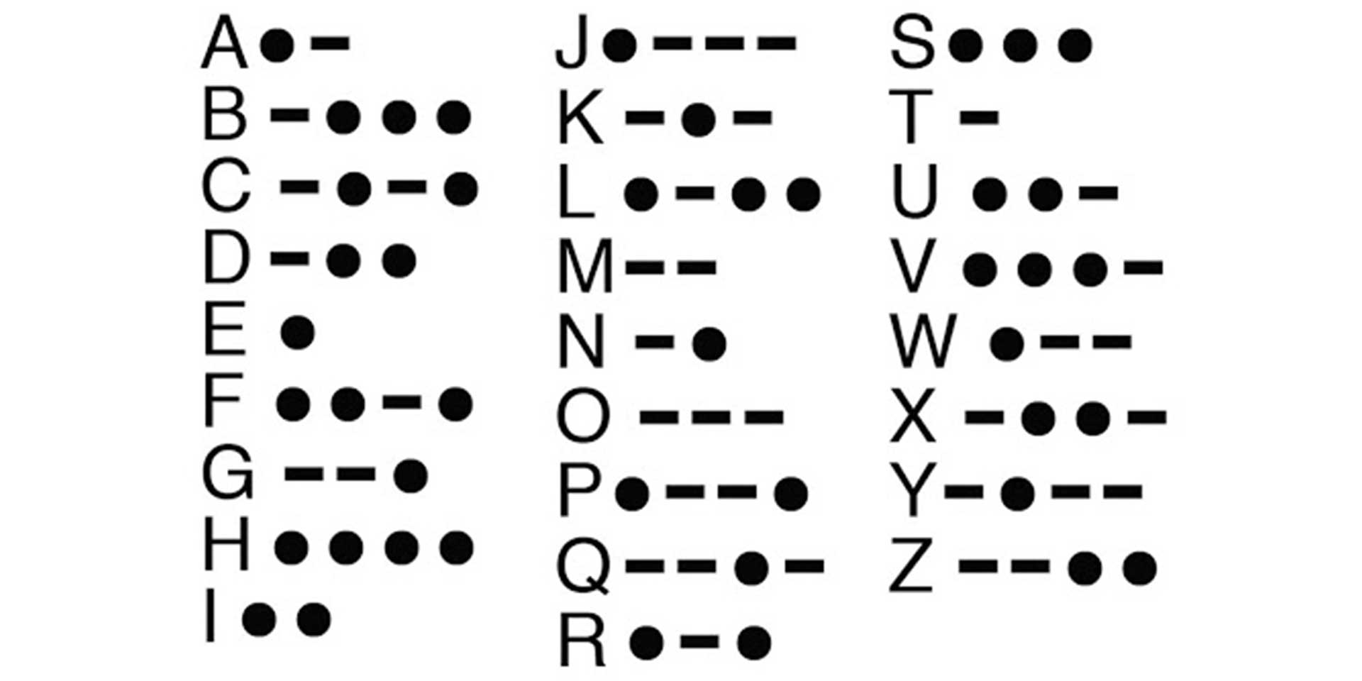
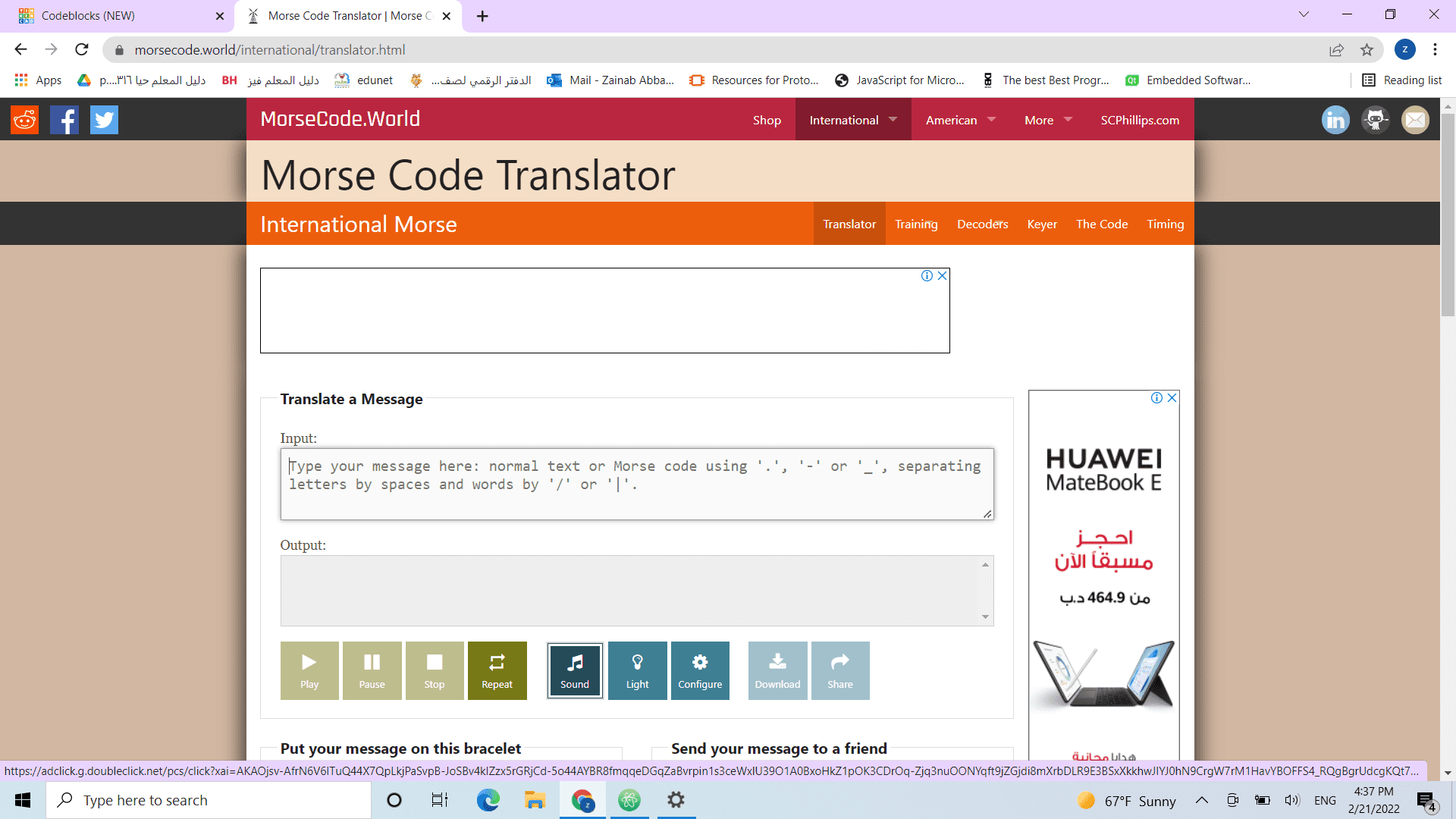 Morse code alphaphets are aassampled in dots and dashes ordered in various patterns.
The light will be on for a specific duration depending on the mark :
- The dash(-)means the light is on for 1s
- The dot (.) means the ligh is on for 0.5 s
- The space between one letter is 0.25s
- The space between two letters is 2s
Morse code alphaphets are aassampled in dots and dashes ordered in various patterns.
The light will be on for a specific duration depending on the mark :
- The dash(-)means the light is on for 1s
- The dot (.) means the ligh is on for 0.5 s
- The space between one letter is 0.25s
- The space between two letters is 2s
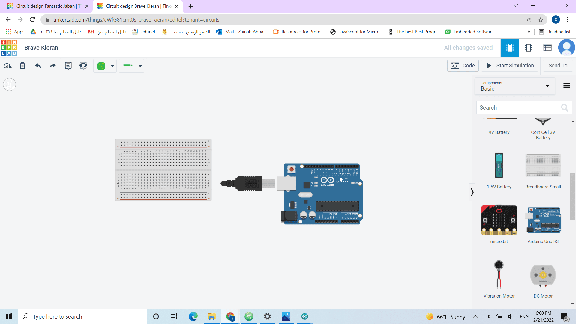
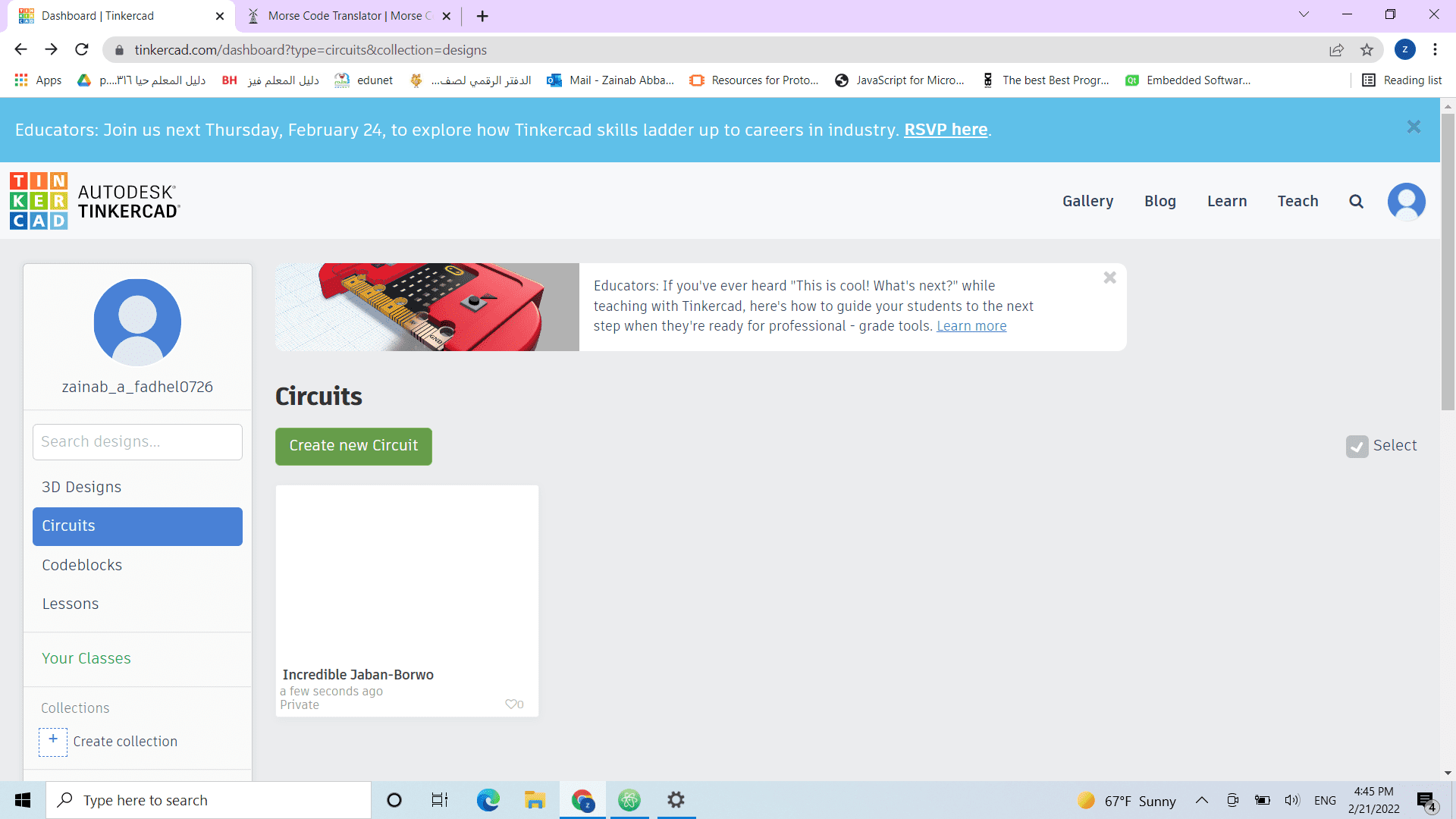
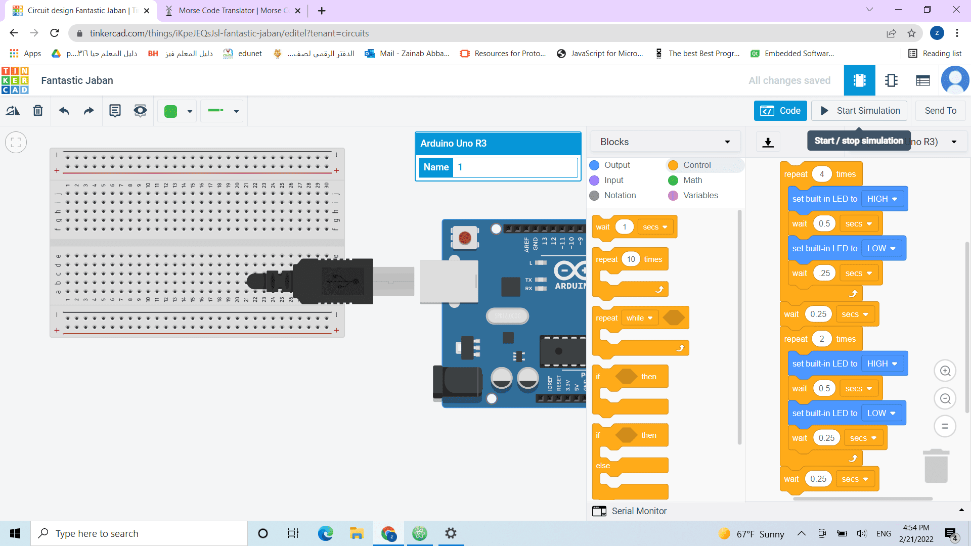
 Tinker cad is a website for 3D designs but it has a feature to create circuits and program it in a simple way
- click circut and create new design (as shown in the picture bellow)
Tinker cad is a website for 3D designs but it has a feature to create circuits and program it in a simple way
- click circut and create new design (as shown in the picture bellow)
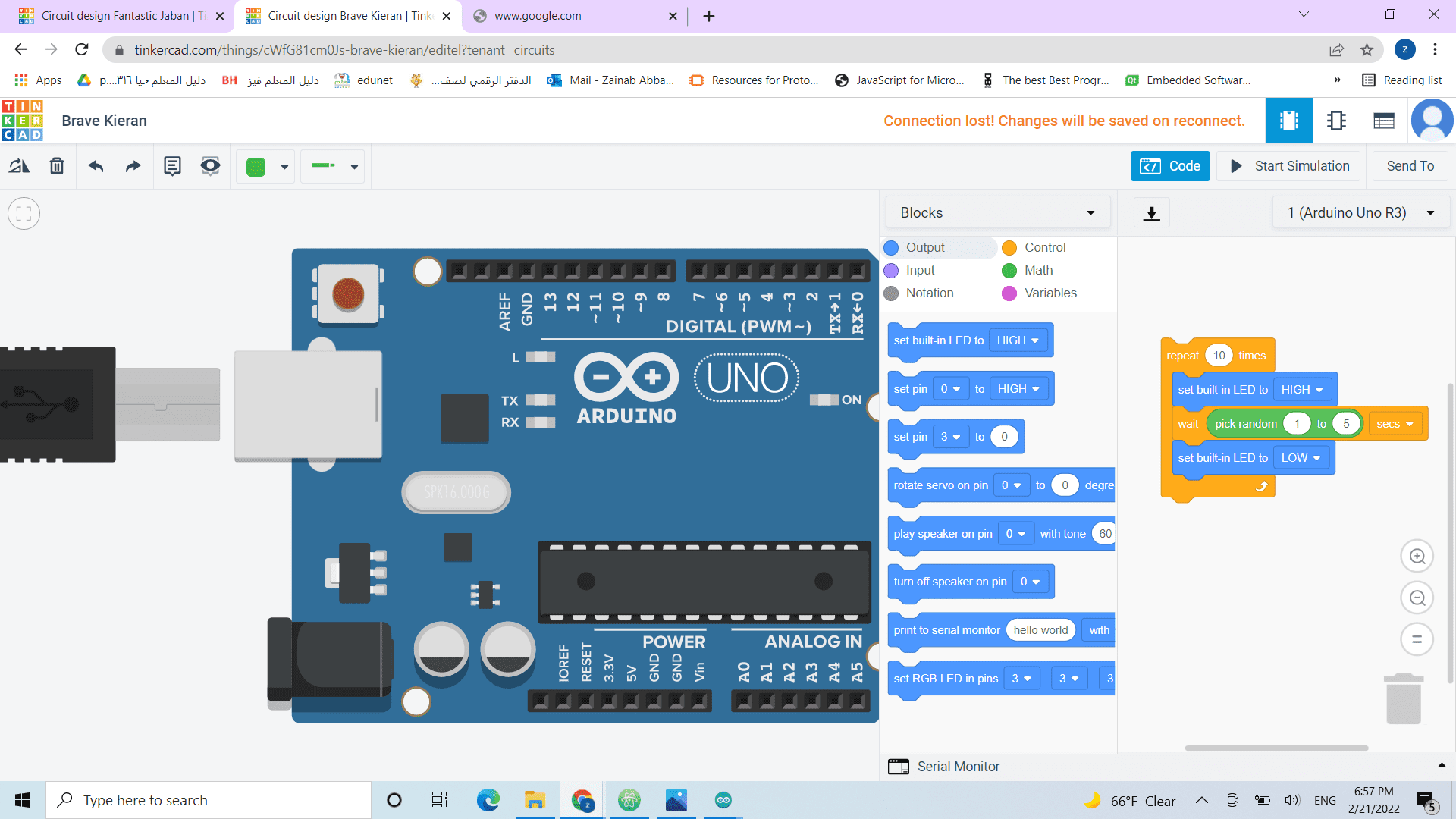
drag an arduino uno board and start programming it
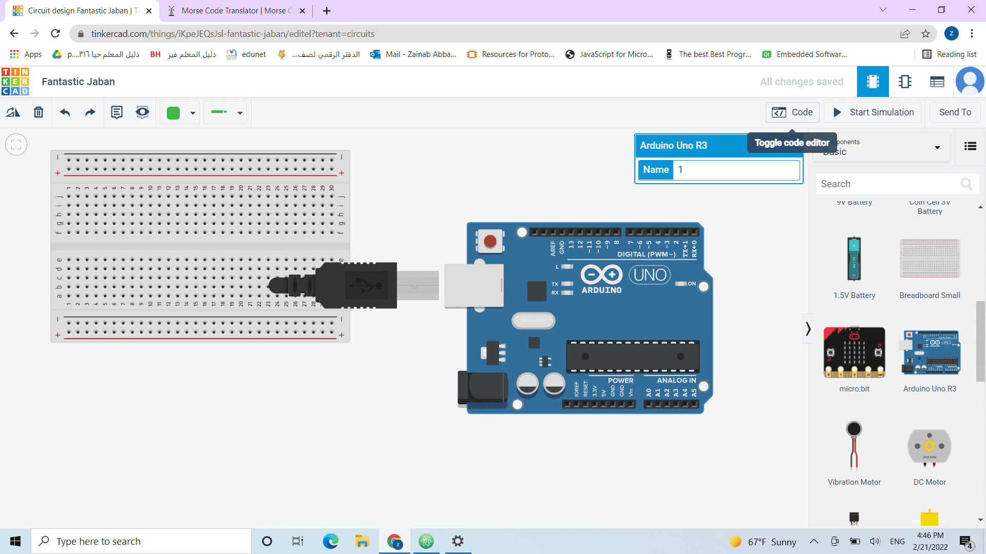
The easiest methoud to program a microcontroller is using blocks (drag and drop)
- adjust the duration according to the Morse code and start the simulation
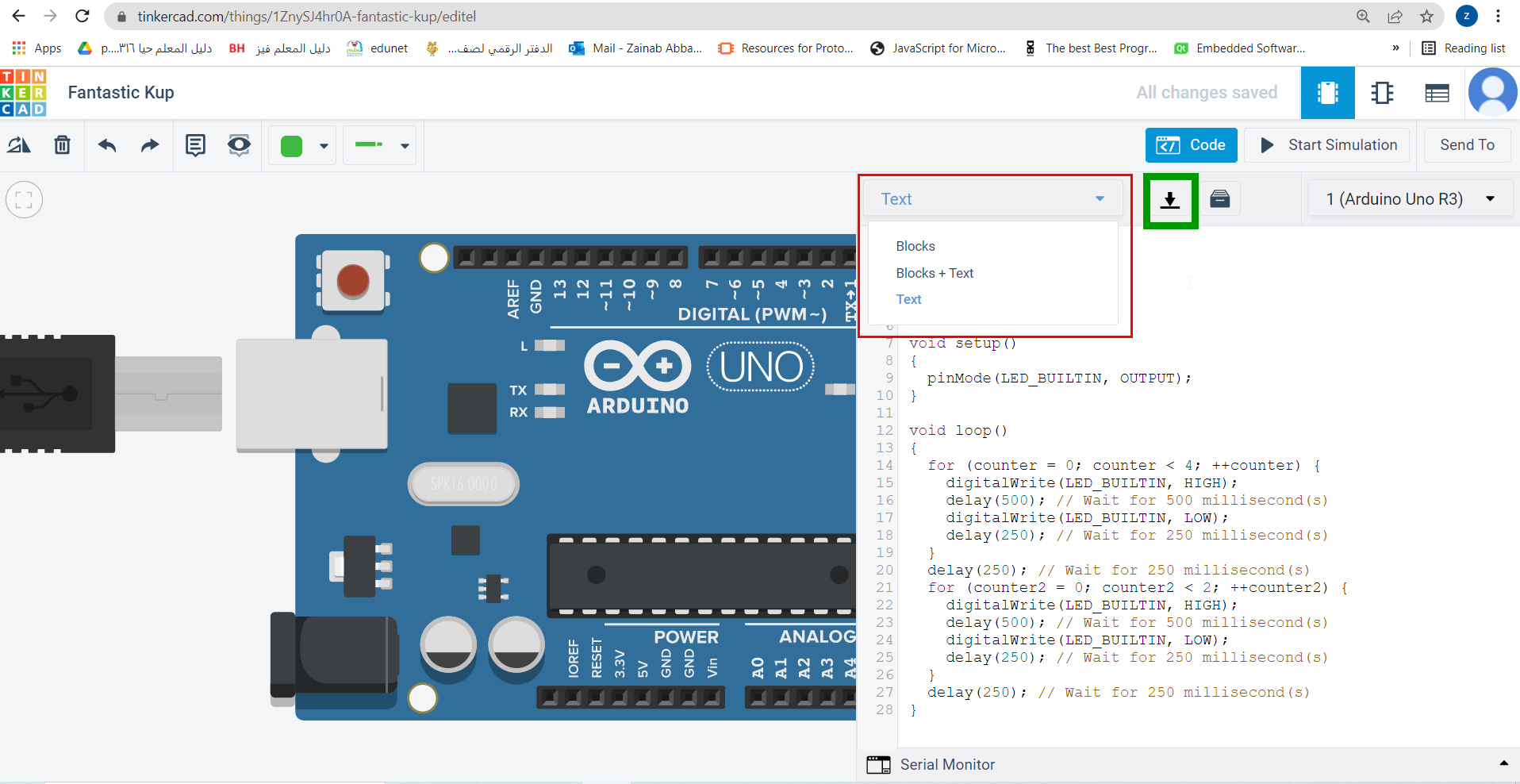
you can change the blocks to text from the list(shown in red)
and you can export the text by downloding the codes (shown in green) or select ,copy and paste
 The task was to pre code your microcontroller to send a Morse code 1 word message and challenge a friend,
family member, your colleagues or your instructor to figure it out. dot = 0.5 second light on.
dash=1 second light on.
gap between dots and dashes=0.5 second light off. gap between letters=2 second light off
First think of a word to challenge others
- convert the word in any Morse code translator
- follow the rule for each symbol
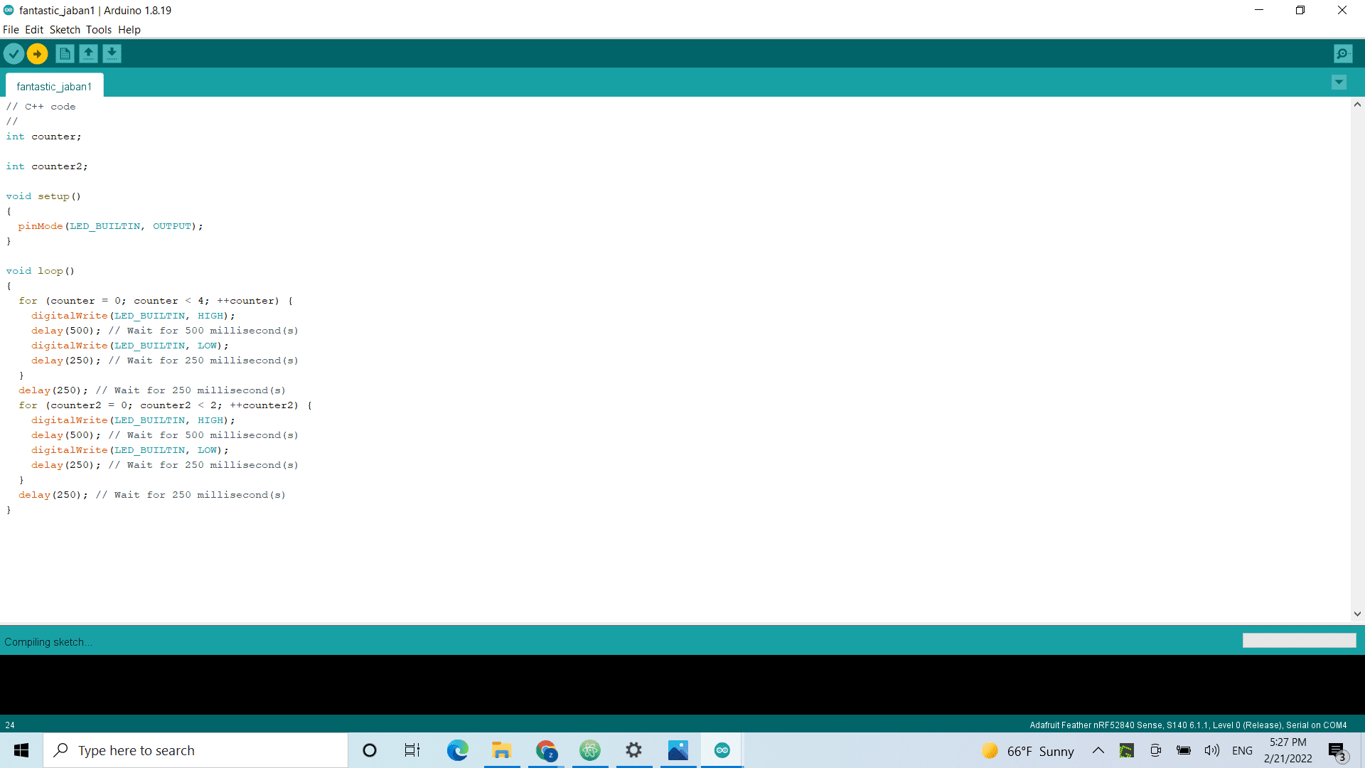
- this was the final codes if want to give it a try
The task was to pre code your microcontroller to send a Morse code 1 word message and challenge a friend,
family member, your colleagues or your instructor to figure it out. dot = 0.5 second light on.
dash=1 second light on.
gap between dots and dashes=0.5 second light off. gap between letters=2 second light off
First think of a word to challenge others
- convert the word in any Morse code translator
- follow the rule for each symbol
- this was the final codes if want to give it a try
// C++ code
//
int counter;

void setup()
{
  pinMode(LED_BUILTIN, OUTPUT);
}

void loop()
{
  for (counter = 0; counter < 4; ++counter) {
    digitalWrite(LED_BUILTIN, HIGH);
    delay(500); // Wait for 500 millisecond(s)
    digitalWrite(LED_BUILTIN, LOW);
    delay(250); // Wait for 250 millisecond(s)
  }
  delay(1750); // Wait for 1750 millisecond(s)
  digitalWrite(LED_BUILTIN, HIGH);
  delay(500); // Wait for 500 millisecond(s)
  digitalWrite(LED_BUILTIN, LOW);
  delay(2000); // Wait for 2000 millisecond(s)
  digitalWrite(LED_BUILTIN, HIGH);
  delay(500); // Wait for 500 millisecond(s)
  digitalWrite(LED_BUILTIN, LOW);
  delay(250); // Wait for 250 millisecond(s)
  digitalWrite(LED_BUILTIN, HIGH);
  delay(1000); // Wait for 1000 millisecond(s)
  digitalWrite(LED_BUILTIN, LOW);
  delay(250); // Wait for 250 millisecond(s)
  digitalWrite(LED_BUILTIN, HIGH);
  delay(500); // Wait for 500 millisecond(s)
  digitalWrite(LED_BUILTIN, LOW);
  delay(250); // Wait for 250 millisecond(s)
  digitalWrite(LED_BUILTIN, HIGH);
  delay(500); // Wait for 500 millisecond(s)
  digitalWrite(LED_BUILTIN, LOW);
  delay(2000); // Wait for 2000 millisecond(s)
  digitalWrite(LED_BUILTIN, HIGH);
  delay(500); // Wait for 500 millisecond(s)
  digitalWrite(LED_BUILTIN, LOW);
  delay(250); // Wait for 250 millisecond(s)
  digitalWrite(LED_BUILTIN, HIGH);
  delay(1000); // Wait for 1000 millisecond(s)
  digitalWrite(LED_BUILTIN, LOW);
  delay(250); // Wait for 250 millisecond(s)
  digitalWrite(LED_BUILTIN, HIGH);
  delay(1000); // Wait for 1000 millisecond(s)
  digitalWrite(LED_BUILTIN, LOW);
  delay(250); // Wait for 250 millisecond(s)
  digitalWrite(LED_BUILTIN, HIGH);
  delay(500); // Wait for 500 millisecond(s)
  digitalWrite(LED_BUILTIN, LOW);
  delay(10000); // Wait for 10000 millisecond(s)
}
Morse code hero shot
challenging family and friends
The Adafruit doing the blinking.
It was harder than it looks.