

Alright, CNC week! This week, we're diving into the world of Computer Numerical Control machines – those awesome, automated milling machines that carve 3D shapes out of materials with crazy precision. The assignment? Design and build something big using the CNC, focusing on joinery techniques. It's all about learning how to design for CNC production and actually making something useful. Here's how it went down.
This week's group assignment was all about getting to grips with the CNC router and understanding its quirks. You can check out our detailed group work here. It was a real team effort, and we covered a lot of ground, from safety protocols to optimizing cutting parameters.
First off, safety is paramount. We completed our lab's safety training, emphasizing the importance of protective eyewear, appropriate clothing, and understanding the emergency stop procedures. As the group assignment page mentions, wearing safety glasses and soundproof headsets are a must. We also made sure everyone knew the location of the emergency stop buttons – one on the machine and another near the computer – and understood the difference between the green (running) and blue (reset) states.
A significant part of the group assignment involved testing the CNC's capabilities. We experimented with runout, alignment, fixturing, speeds, feeds, materials, and toolpaths. According to our group's findings, we discovered that the optimal speed is 90, while the ideal feed rate is 14,000. We learned that finding the right balance between feed rate and spindle speed is crucial for efficient cutting. As the group assignment page points out, simply increasing both doesn't necessarily lead to faster cutting times. It's about maximizing the material removed, which is evident in the volume of sawdust and the sound of the operation.
Proper fixturing and machine setup are also critical. We made sure the platform was parallel to the supported plate and securely fixed the board in place using screws. We also paid close attention to the origin point, using the iron plate and clip to accurately adjust the drill's position. As the group assignment page emphasizes, ensuring the clip is connected is essential for completing the electrical circuit.
Through this group assignment, I gained a deeper appreciation for the complexities of CNC machining. It's not just about pushing a button and letting the machine do its thing. It requires a thorough understanding of safety procedures, material properties, machine capabilities, and toolpath optimization. I also learned the importance of teamwork and communication in tackling complex projects.
This week had two main parts:
First things first, gotta know what you're working with! I carefully measured the thickness of the wood we were using. This is super important because the joinery design depends on it.

Turns out, our wood was 11.22mm thick. This measurement became the foundation for my design in Fusion 360.
With the material thickness in hand, I jumped into Fusion 360 to design the joint test. The goal was to create a series of joints with slightly different offsets to find the sweet spot for a snug fit. After designing, I exported the design in DXF format.

Next up, VCarve! This software is key for creating the toolpaths that the CNC machine will follow. I imported the DXF file into VCarve. VCarve lets you create exciting 3D carving from a simple 2D image.

Then, I arranged all the drawings inside the workspace, making sure they were close together to maximize material usage. Waste not, want not!

This is a crucial step! To ensure the joints fit together properly, especially in the corners, I added "dog-bone" fillets. These fillets are special because they create a circular arc that is outside of the edges. The point of intersection for both edges is actually the mid-point of the arc.

Without these, the joints wouldn't fit because the CNC bit can't make perfect square corners.
Time to tell the CNC how to cut! I selected the appropriate toolpath operation. This involves specifying the cutting depth, the type of bit, and the cutting speed.

To keep the pieces from moving during the cutting process, I added tabs to the toolpath. These are small connections that hold the pieces in place. I added two tabs to make the cutting more accurate. The tabs are the number of time the machine going to cut the same line.

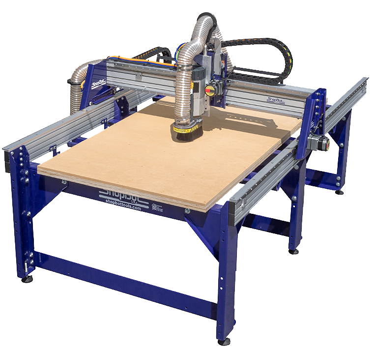
With the toolpath all set, I saved it in the correct format (.sbp) for the ShopBot CNC machine.

Now for the real deal! Setting up the ShopBot is a process. First, I secured the wood to the CNC bed. Then, I had to calibrate the z-axis. This involves using a metal plate and a clip to accurately set the height of the cutting bit.

I also made sure the starting point for the x and y axes was at the edge of the material, so the cuts would align with my design.
With everything calibrated and secured, it was time to let the ShopBot do its thing! I uploaded the toolpath file and started the cutting process. Of course, I made sure the vacuum system was running to collect all the sawdust.

After the cutting, I carefully removed the test joints and started experimenting with the fit.

I tested multiple different ratio between the original size of the joint, and I ended up that 0.2mm is the good fitting for me. It turned out that an offset of 0.2mm provided the best, snug fit. This meant that the slots needed to be 0.2mm wider than the tabs for a perfect connection.

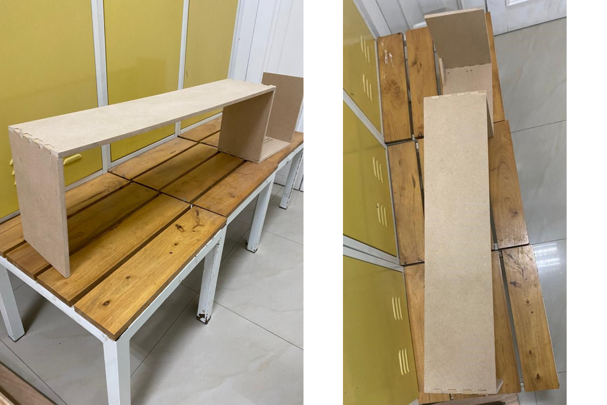
With the perfect joint offset figured out, I moved on to designing the "something big" – a small shelf! I designed the shelf in Fusion 360, incorporating the 0.2mm offset into all the joints.
This is the unassembled version for it with 0.2mm joint gap.
I followed the same process as before, importing the shelf design into VCarve, creating the toolpath, setting up the ShopBot, and letting it cut.
And here it is – the finished shelf! It's not huge, but it's "something big" enough for this assignment. The joints fit together perfectly thanks to the joint test, and it's actually a pretty useful little shelf.
Of course, things didn't go perfectly smoothly. One of the biggest challenges was getting the z-axis calibration just right. If it's off, the cutting depth will be wrong, and the joints won't fit properly. I had to re-calibrate a couple of times to get it dialed in.
Another issue was with the tabs. I didn't make them quite big enough, and a couple of pieces started to shift during the cutting process. Next time, I'll make sure the tabs are more substantial.
Here are the design files for the joint test and the shelf:
This week was a great introduction to the world of CNC machining. It was challenging, but also incredibly rewarding to see a design come to life. I learned a lot about the importance of accurate measurements, careful design, and proper machine setup. I'm looking forward to using these skills in future projects!