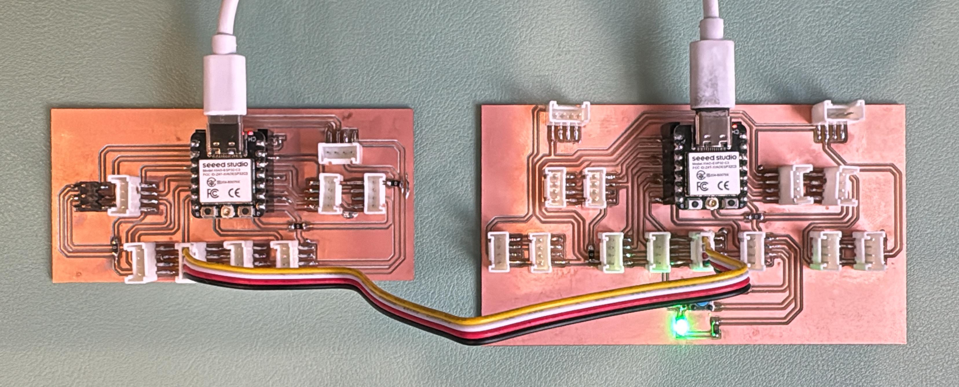
This week I dove into embedded networking by getting two microcontroller boards to talk to each other. I used my custom Grove-style board built around the XIAO ESP32C3, which made it really easy to plug things in and start experimenting.
The goal was simple: use I2C communication to send data from one board (the master) to another (the slave) and have that data control an LED on the receiving end.
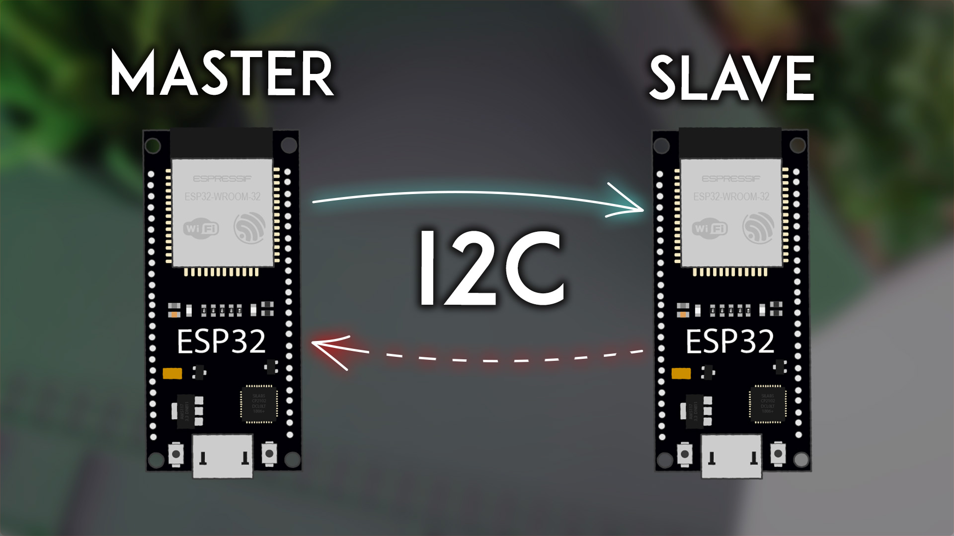
I went with I2C for this — a reliable two-wire protocol that’s perfect for communication between microcontrollers over short distances.
Wiring Setup:
One board played the role of master, sending commands, while the other acted as the slave, responding by turning an LED on or off.
Here’s what each board does:
'1' or '0' every 2 seconds to tell the slave whether to turn the LED on or off.
#include <Wire.h>

void setup() {
  Wire.begin(); // Join I2C bus as master
  Serial.begin(115200);
}

void loop() {
  Wire.beginTransmission(8); // Address of the slave
  Wire.write("1");       	// Command to turn on LED
  Wire.endTransmission();
  Serial.println("Sent: 1");
  delay(2000);

  Wire.beginTransmission(8);
  Wire.write("0");       	// Command to turn off LED
  Wire.endTransmission();
  Serial.println("Sent: 0");
  delay(2000);
}
#include <Wire.h>
#define LED_PIN 20

void setup() {
  Wire.begin(8);
  Wire.onReceive(receiveEvent);
  pinMode(LED_PIN, OUTPUT);
  Serial.begin(115200);
}

void loop() {
  // Main logic handled in receiveEvent
}

void receiveEvent(int howMany) {
  while (Wire.available()) {
    char c = Wire.read();
    if (c == '1') {
      digitalWrite(LED_PIN, HIGH);
      Serial.println("LED ON");
    } else if (c == '0') {
      digitalWrite(LED_PIN, LOW);
      Serial.println("LED OFF");
    }
  }
}
Once everything was connected and flashed, the setup worked perfectly:
What I Learned: