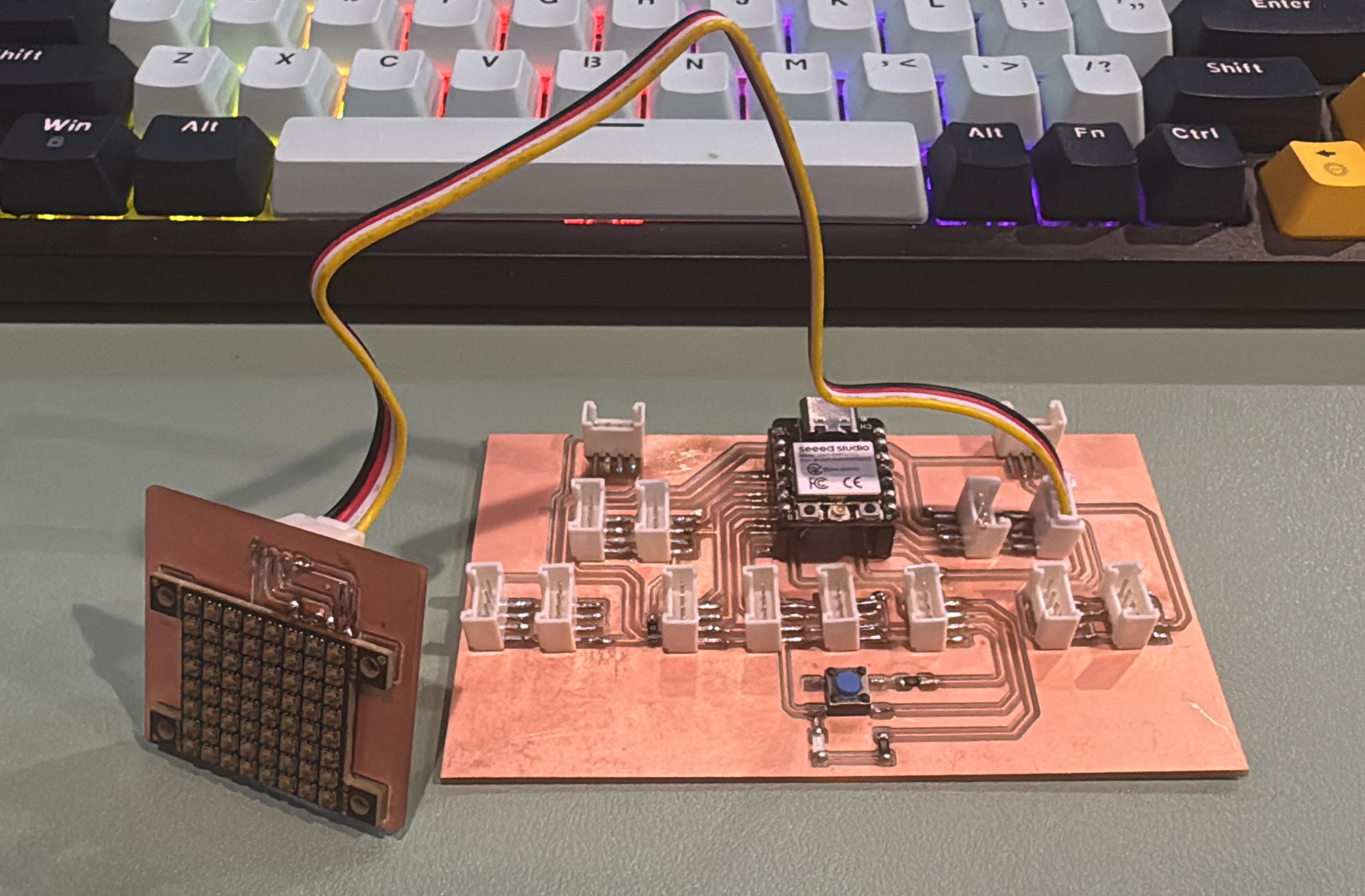
For this week’s assignment, I focused on controlling an output device using the custom Grove-compatible board I designed earlier, which is built around the XIAO ESP32C3.
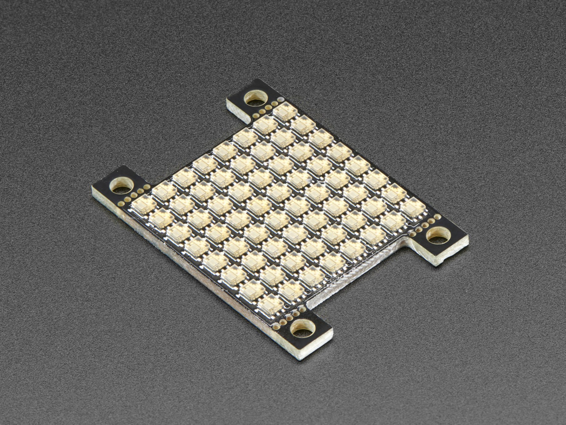
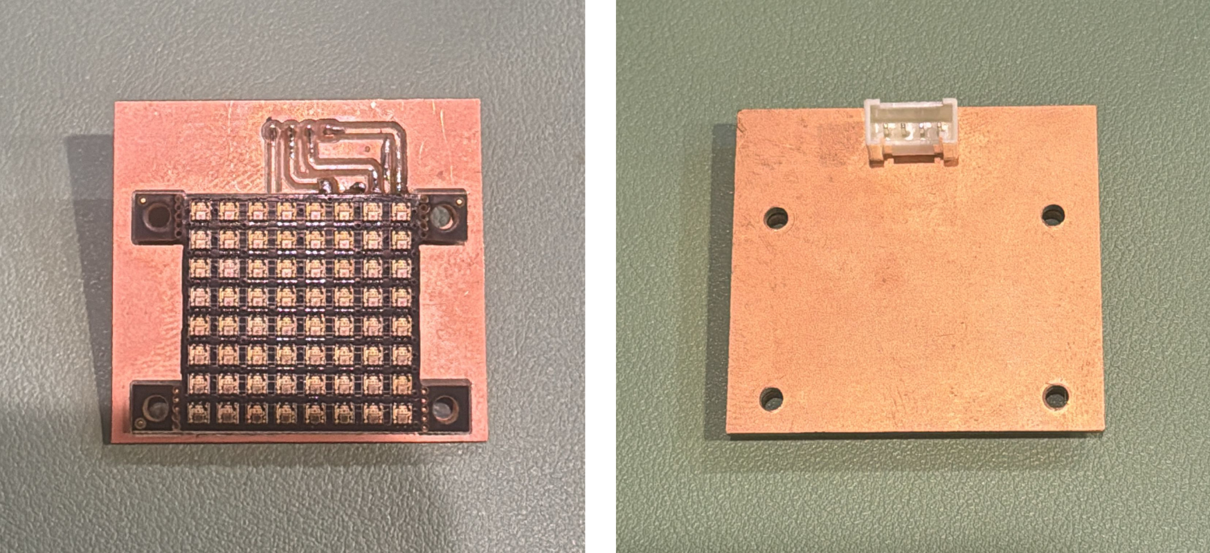
Instead of using a simple LED, I decided to go with something more exciting — the Adafruit DotStar HD 8x8 RGB LED Grid. This grid has 64 individually addressable RGB LEDs, which means I can light up each LED in any color I want. It’s a fun and powerful way to explore how microcontrollers can control complex output devices!
The DotStar Grid uses SPI communication, which means I needed two pins: one for data and one for clock. Here’s how I connected it to my board:
This setup let me run light patterns without any extra circuits or components — simple and clean thanks to the Grove-style connections.
I used the Adafruit DotStar library in the Arduino IDE to get things up and running. Here’s a simple test I wrote — each LED turns on one-by-one in red, and only one LED is lit at a time:
This code listens to the Serial Monitor for a color name (e.g., red, green, blue) and then lights up the DotStar Grid one LED at a time in the selected color. Only one LED lights up at a time, looping through all 64 pixels.
This gives a nice “running red light” effect — great for seeing the grid respond in real-time.
#include <Adafruit_DotStar.h>
#include <SPI.h>

#define NUMPIXELS 64
#define DATAPIN   10
#define CLOCKPIN  9

Adafruit_DotStar strip(NUMPIXELS, DATAPIN, CLOCKPIN, DOTSTAR_BGR);

uint8_t red = 255, green = 0, blue = 0; // Default color is red
String inputString = "";
bool newColorEntered = false;

void setup() {
  Serial.begin(115200);
  strip.begin();
  strip.show(); // Initialize all pixels to 'off'
  inputString.reserve(50); // Reserve memory for input
  Serial.println("Enter a color name (e.g., red, green, blue, yellow, cyan, magenta, white, black):");
}

void loop() {
  if (Serial.available()) {
    inputString = Serial.readStringUntil('\n');
    inputString.trim();
    inputString.toLowerCase();
    setColorFromInput(inputString);
    newColorEntered = true;
  }

  // Cycle one LED at a time with current color
  for (int i = 0; i < NUMPIXELS; i++) {
    strip.clear();
    strip.setPixelColor(i, red, green, blue);
    strip.show();
    delay(100);

    // If user entered a new color mid-animation, break and apply new color
    if (Serial.available()) {
      break;
    }
  }
}

void setColorFromInput(String color) {
  if (color == "red") {
    red = 255; green = 0; blue = 0;
  } else if (color == "green") {
    red = 0; green = 255; blue = 0;
  } else if (color == "blue") {
    red = 0; green = 0; blue = 255;
  } else if (color == "yellow") {
    red = 255; green = 255; blue = 0;
  } else if (color == "cyan") {
    red = 0; green = 255; blue = 255;
  } else if (color == "magenta") {
    red = 255; green = 0; blue = 255;
  } else if (color == "white") {
    red = 255; green = 255; blue = 255;
  } else if (color == "black" || color == "off") {
    red = 0; green = 0; blue = 0;
  } else {
    Serial.println("Unknown color. Try red, green, blue, yellow, cyan, magenta, white, or black.");
    return;
  }

  Serial.print("Color set to: ");
  Serial.println(color);
}
Working with the DotStar Grid was genuinely fun — it brought the project to life with rich, colorful visuals and smooth performance. Here are a few standout takeaways:
Overall, this test gave me a solid grasp of how to control addressable LEDs and how crucial timing and precise data updates are when working with these kinds of output devices.
Lighting up 64 full-color LEDs isn’t a small task — especially if they’re all set to white at full brightness! To keep everything running smoothly and safely, here’s how I handled power management during testing:
If I plan to push the grid to its limits in the future — like running all LEDs at max brightness — I’ll definitely use an external 5V power supply just to be safe.