
git
Git is a distributed version control system that tracks changes in any set of computer files.
This week I worked on my website page and started to getting used to the documentation process.
Git is a distributed version control system that tracks changes in any set of computer files.

Duis odio diam, luctus et vulputate vitae, vehicula ac dolor. Pellentesque at urna eget tellus sed etiam.

Duis odio diam, luctus et vulputate vitae, vehicula ac dolor. Pellentesque at urna eget tellus sed etiam.
Duis odio diam, luctus et vulputate vitae, vehicula ac dolor. Pellentesque at urna eget tellus sed etiam.
Duis odio diam, luctus et vulputate vitae, vehicula ac dolor. Pellentesque at urna eget tellus sed etiam.


This page shows the steps, designs and the process of making my final project for FAB Academy 2021.
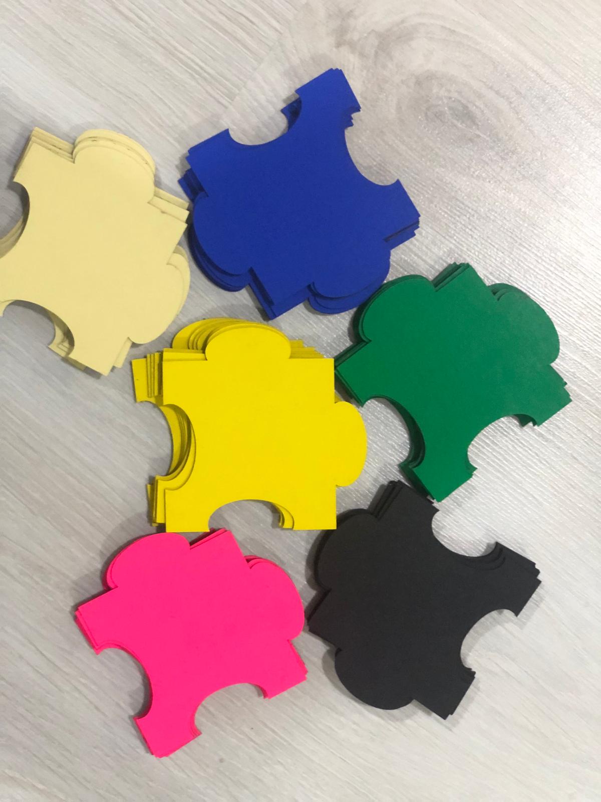
My passion for board games and educating people about the Solar System that we live in drove me to make this board game called Blue Home.

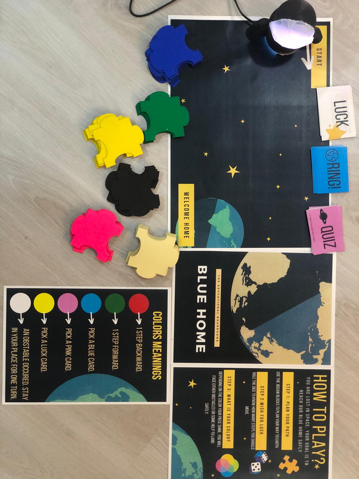
Blue Home is an educational interactive board game, played by 1+ and for ages 6+. Basically, it is for anyone who wants to get to know more about the planets around us and their moons in a fun way. It is about an astronaut who is lost in space and his goal is to reach his Blue Home safely, facing all the quizzes, obstacles, and using all needed help. You are that astronaut and your goal is to reach the Blue Home.
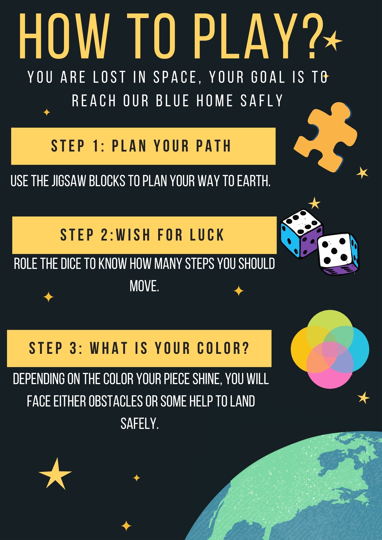
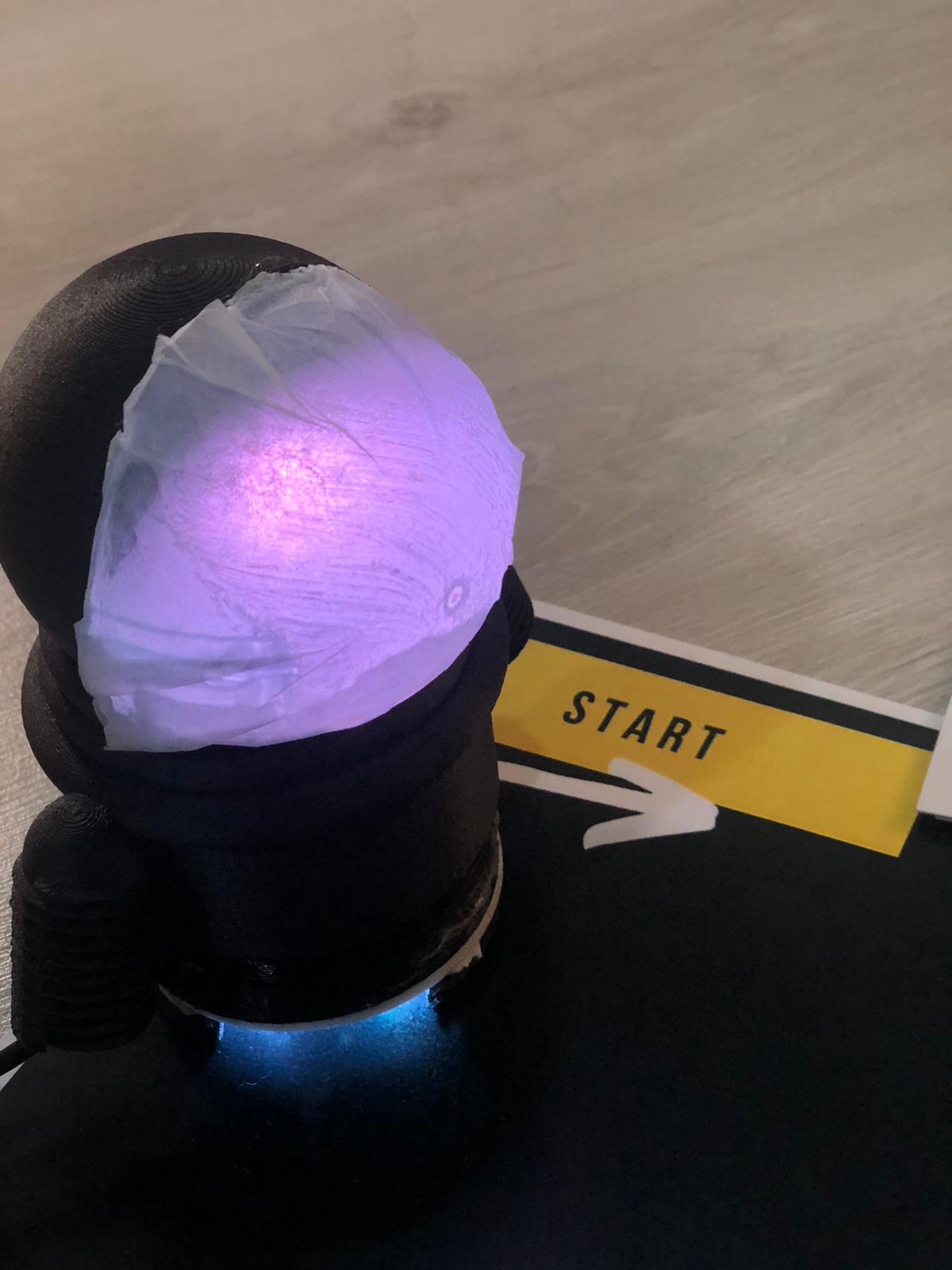
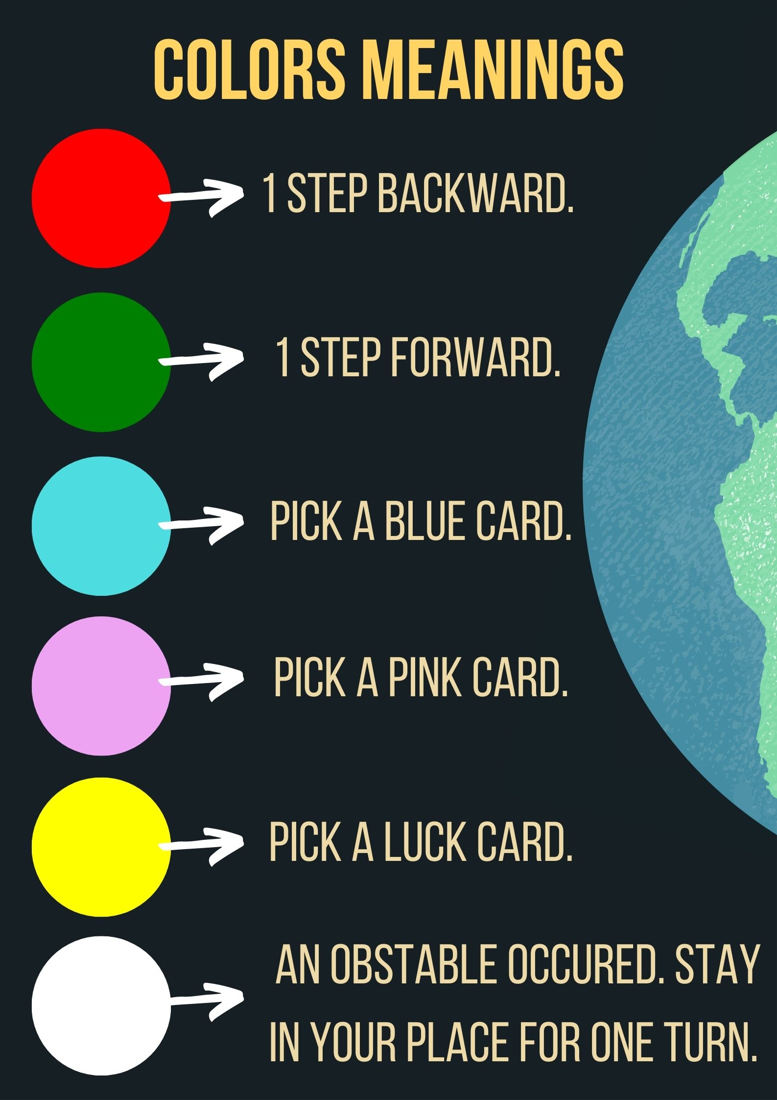
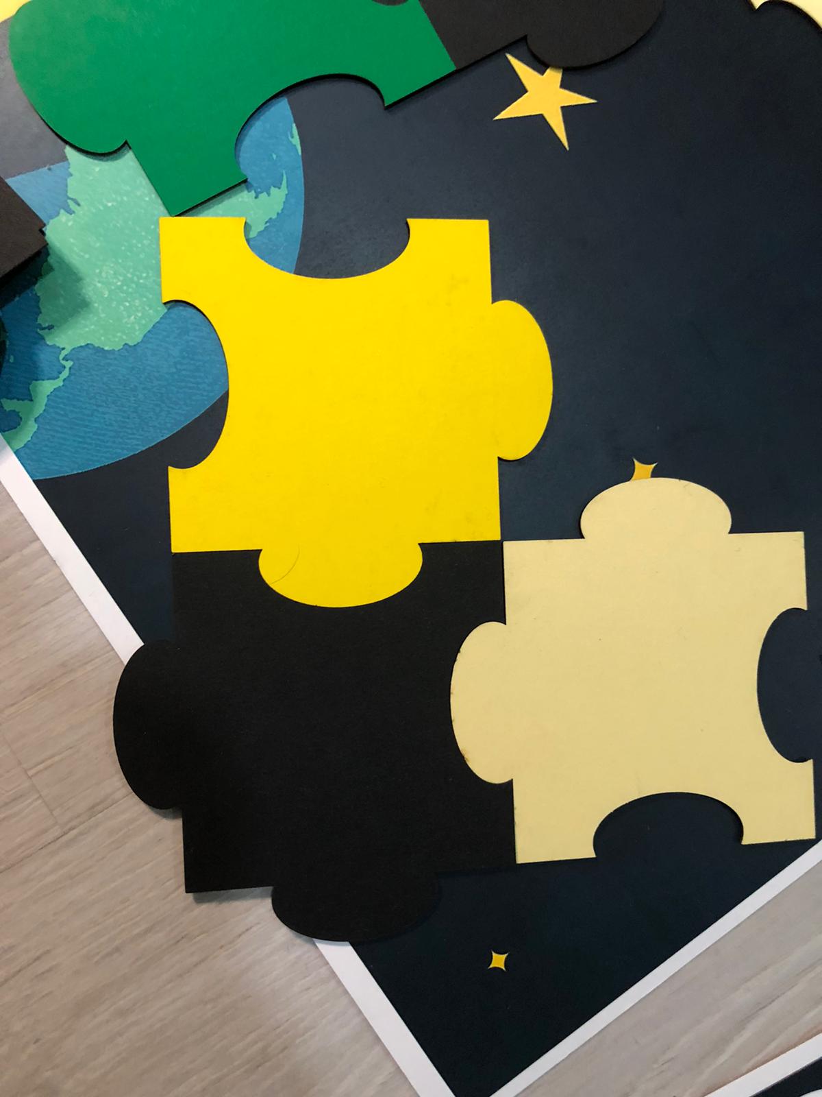
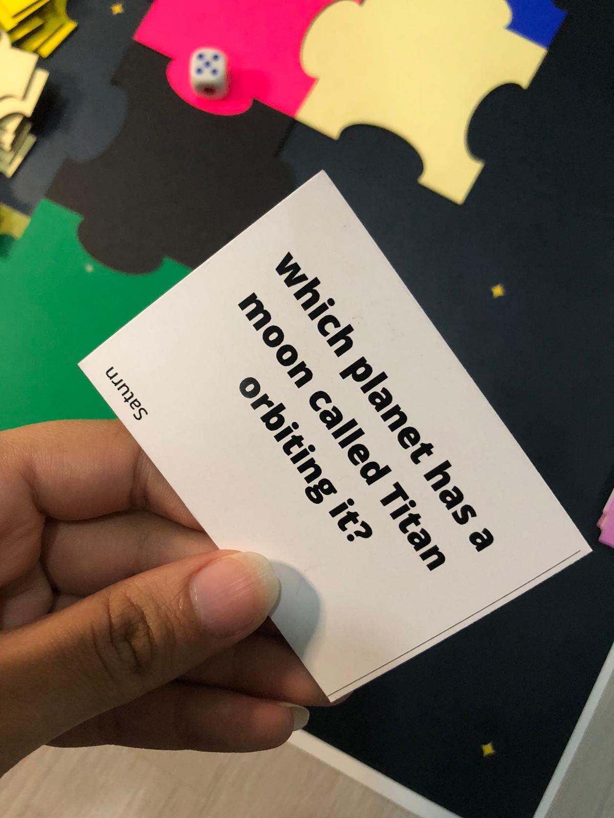
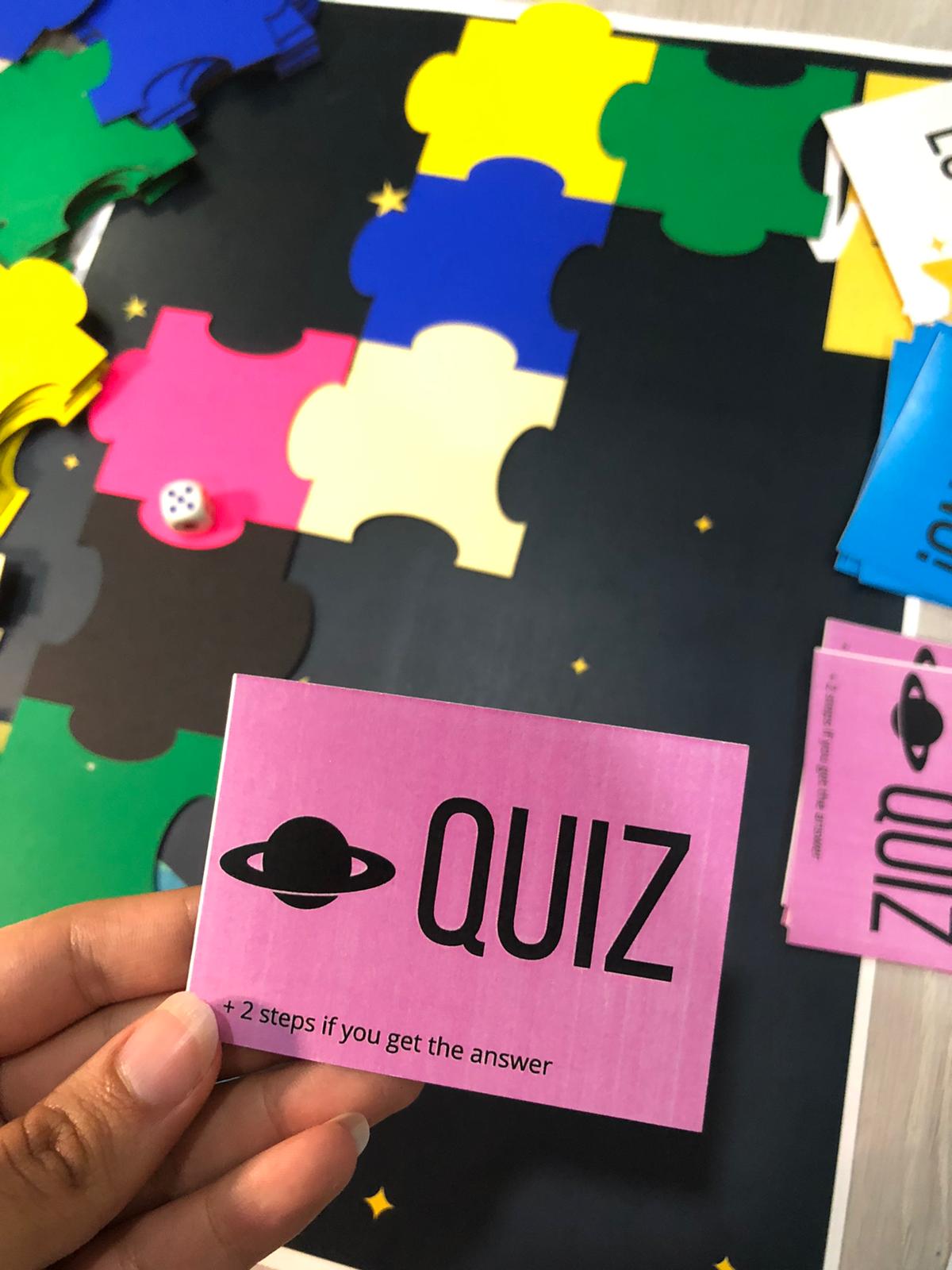
How To Play To Play Blue Home, first build your path using the colored jigsaw pieces. This will be your board that you will move on. After that, role the dice, and move your astronaut. The astronaut will then react randomly by vibrating and shining different colors. Depending on the color your piece shine, you will either move forward or backward, or pick a card.
How does it work The main component of this game is the RGB built-in sensor in the Arduino. It is placed downward to detect the color of the jigsaw piece it is on and based on that there will be various reactions from the RGB LED.
| Qty | Description |
|---|---|
| 6 | Different colors 15mm Cardboard |
| 1 | RGB LED |
| 1 | Arduino Nano 33 BLE Sense |
| 2 | Addressable RGB LED Strips each with 3 LEDs |
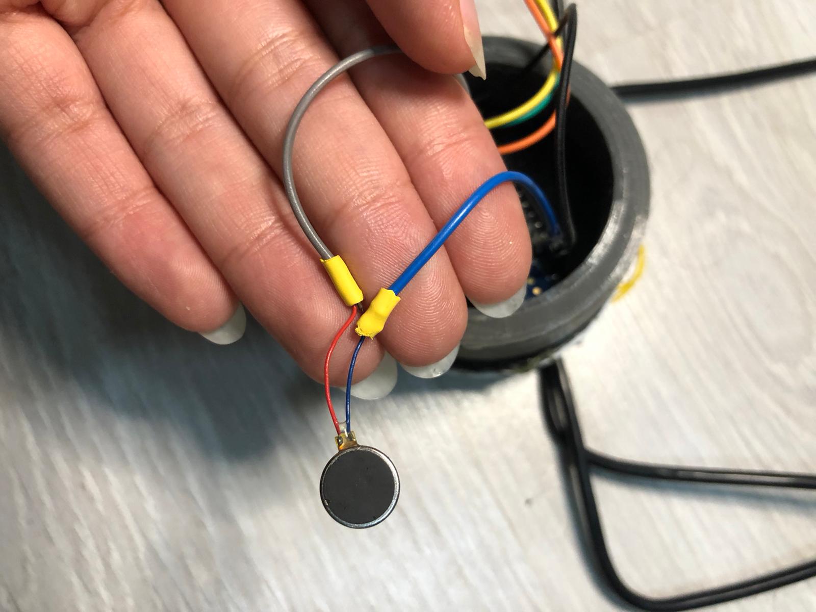
| 1 | Vibrating Mini |
| 1 | 3D printed Astronaut Piece |
| 30 | Printed Cards |
| 1 | Dice |
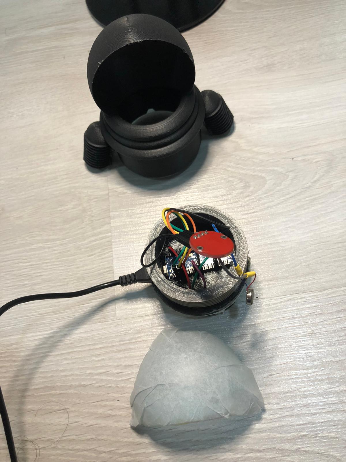
| 1 | Diffusive Paper |
The making of this board game consists of three main steps, fabrication, connecting the electronic parts and coding the game.
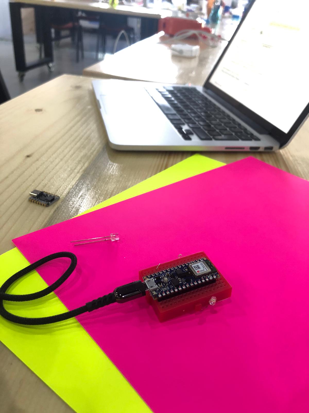
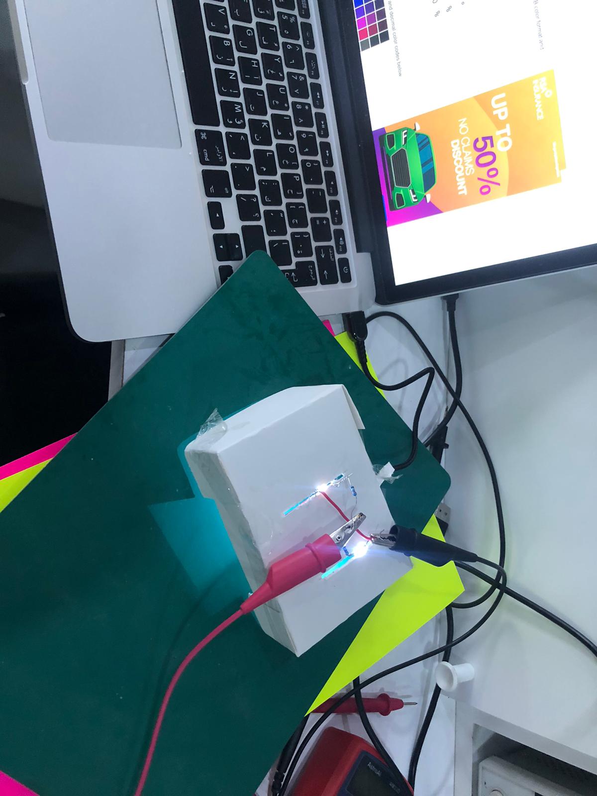
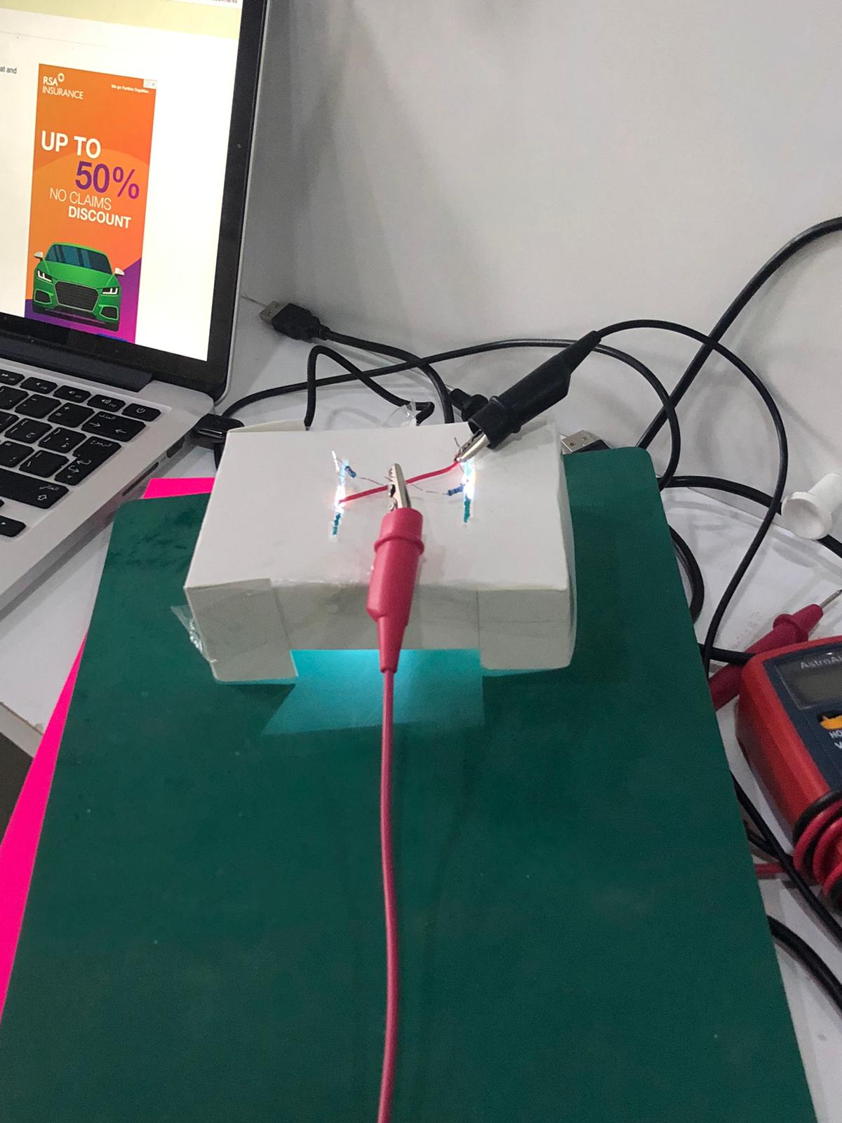
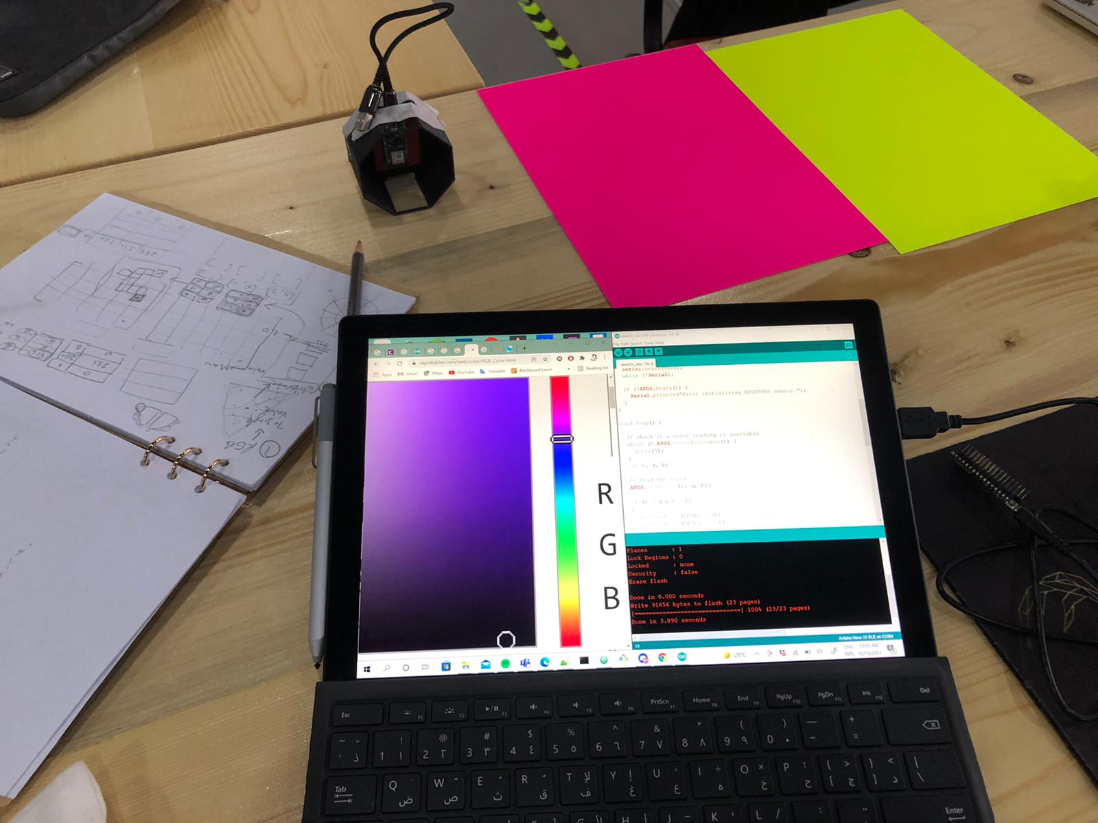
Before going and doing the fabrication, I started by testing the conditions that the RGB sensor will work in.
I started by making a sample model prototype using cardboard, and tested the reading of the sensor.
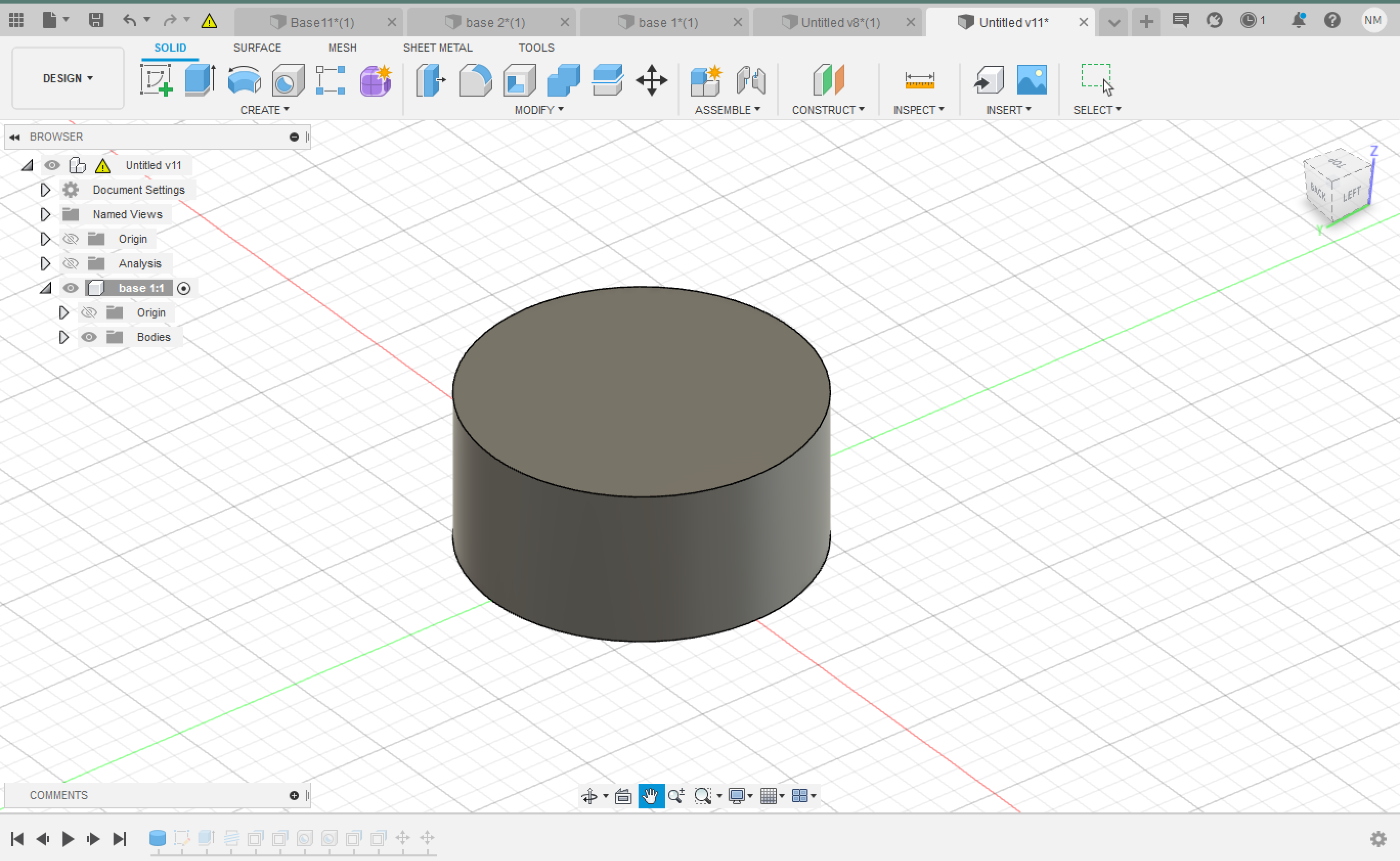
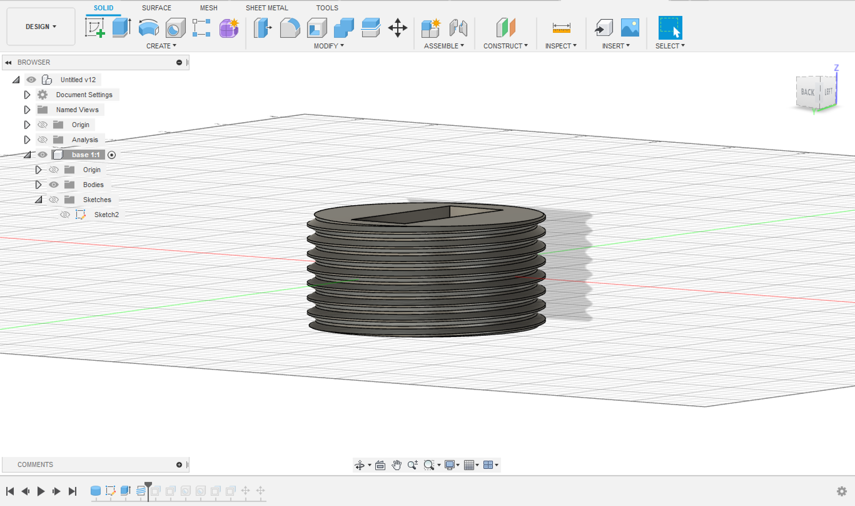
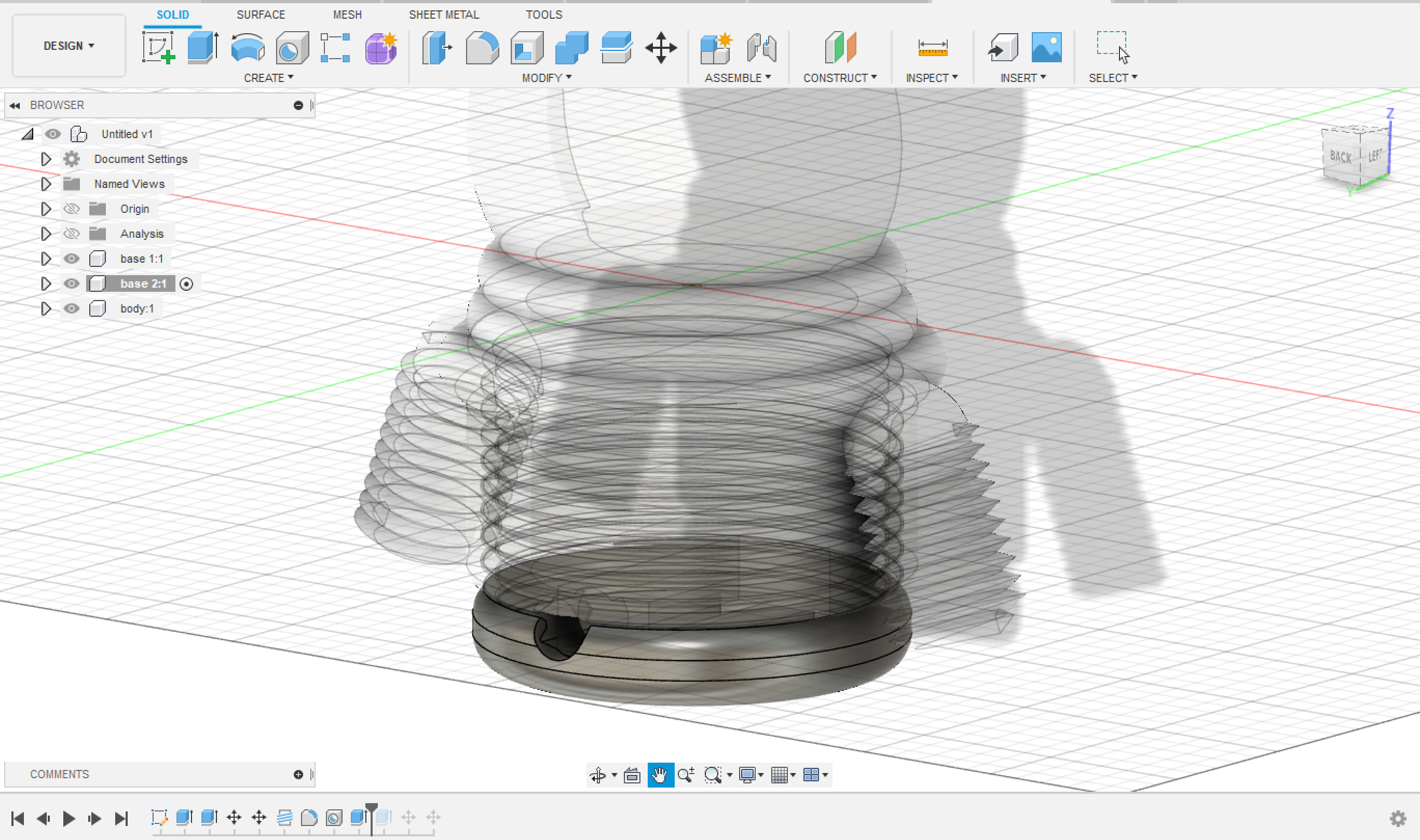
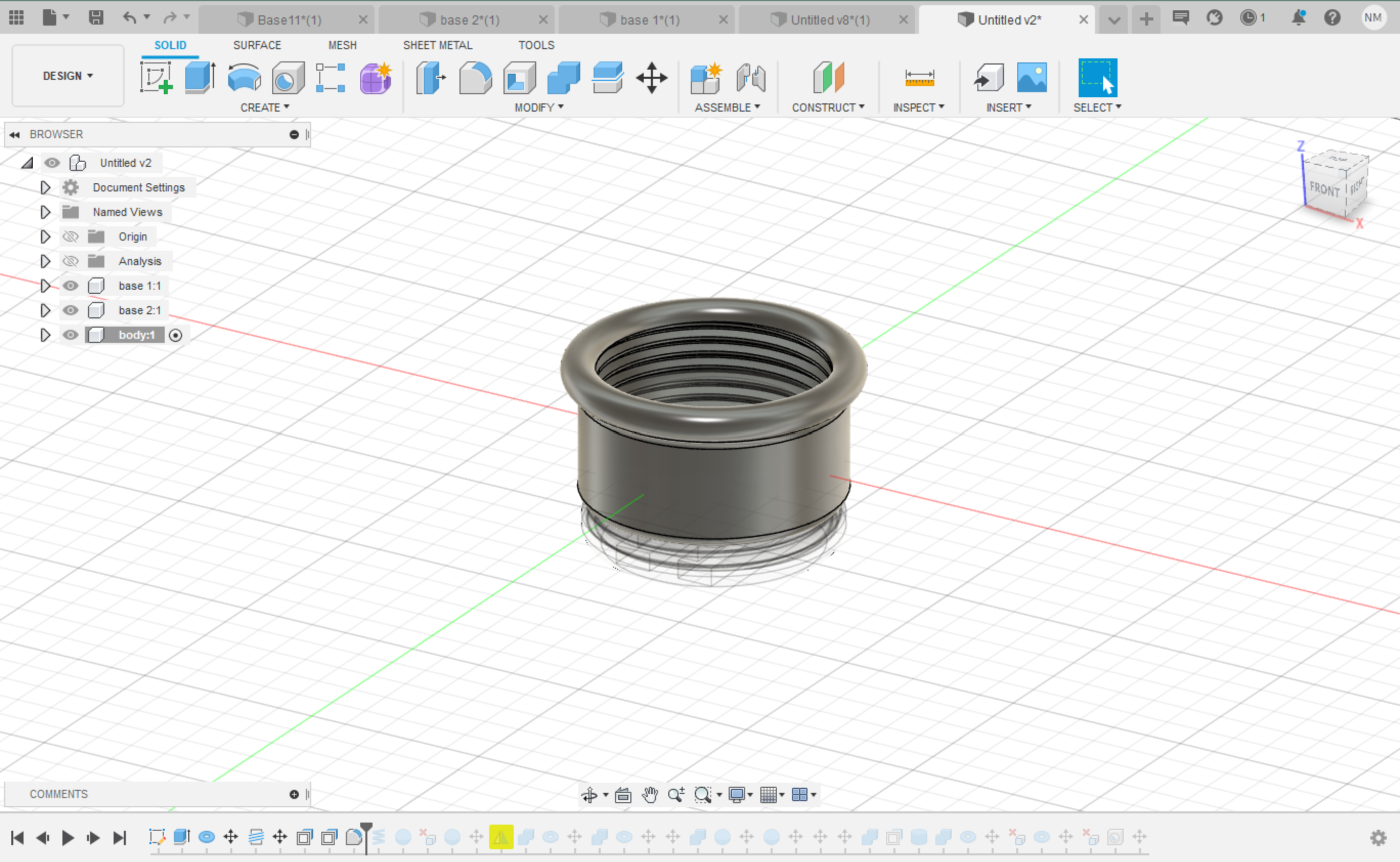
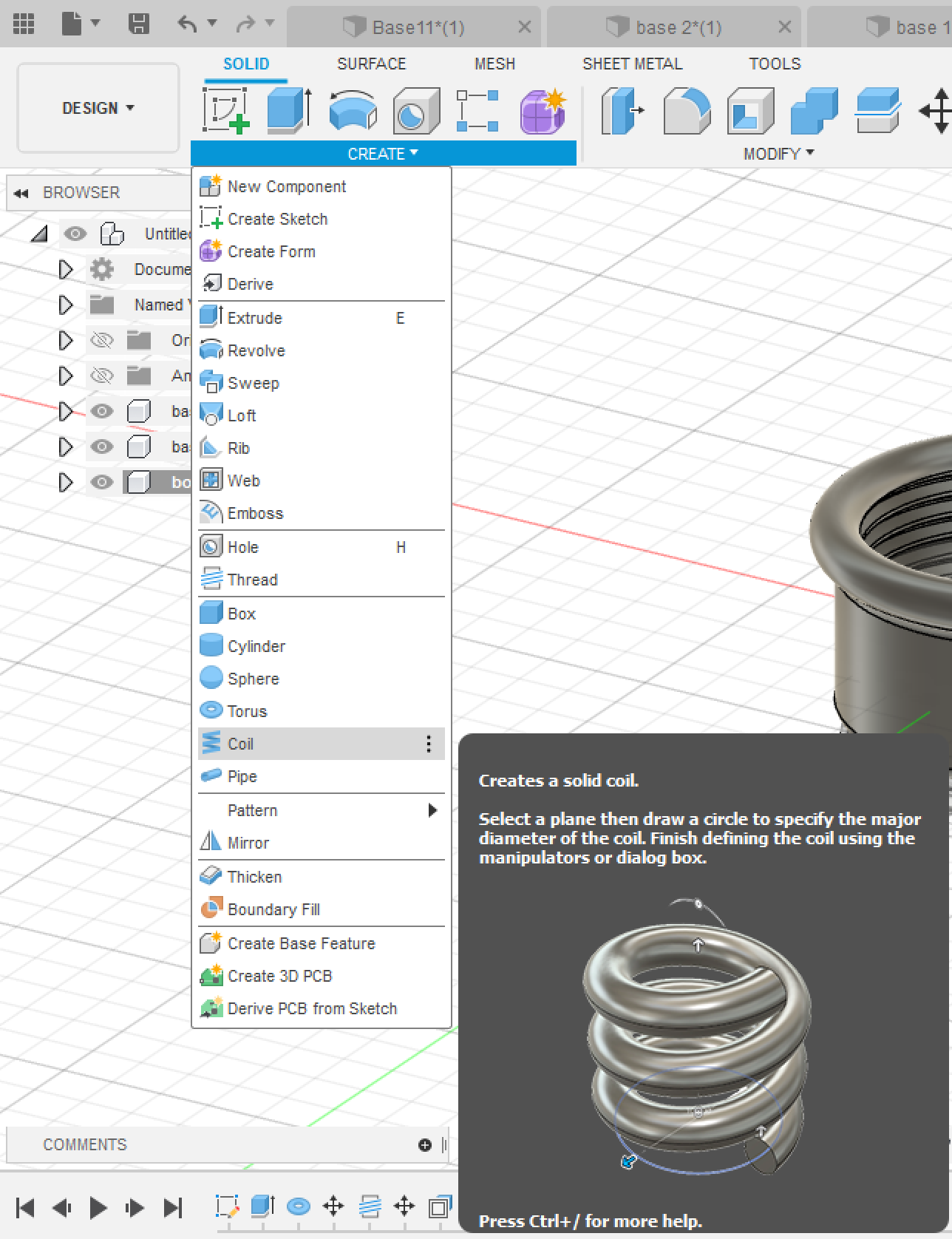
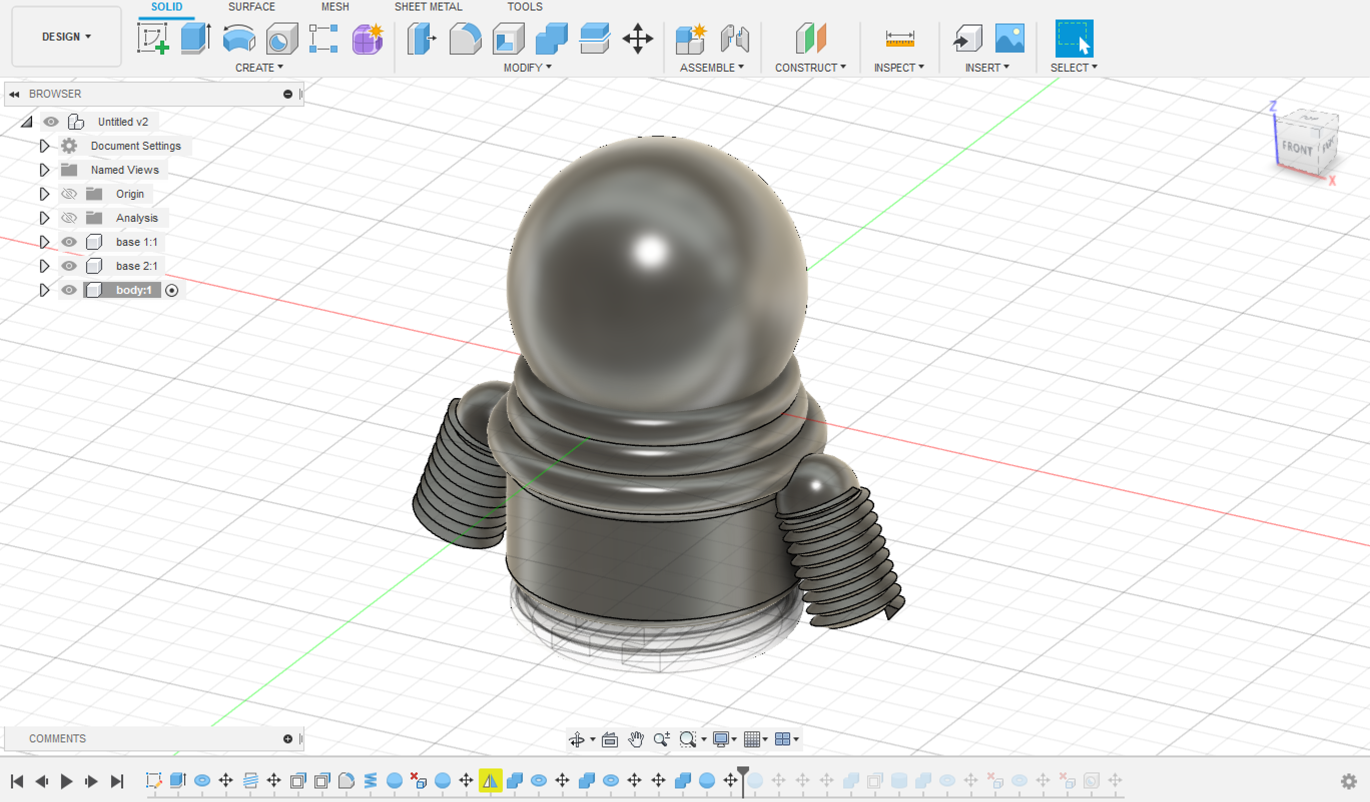
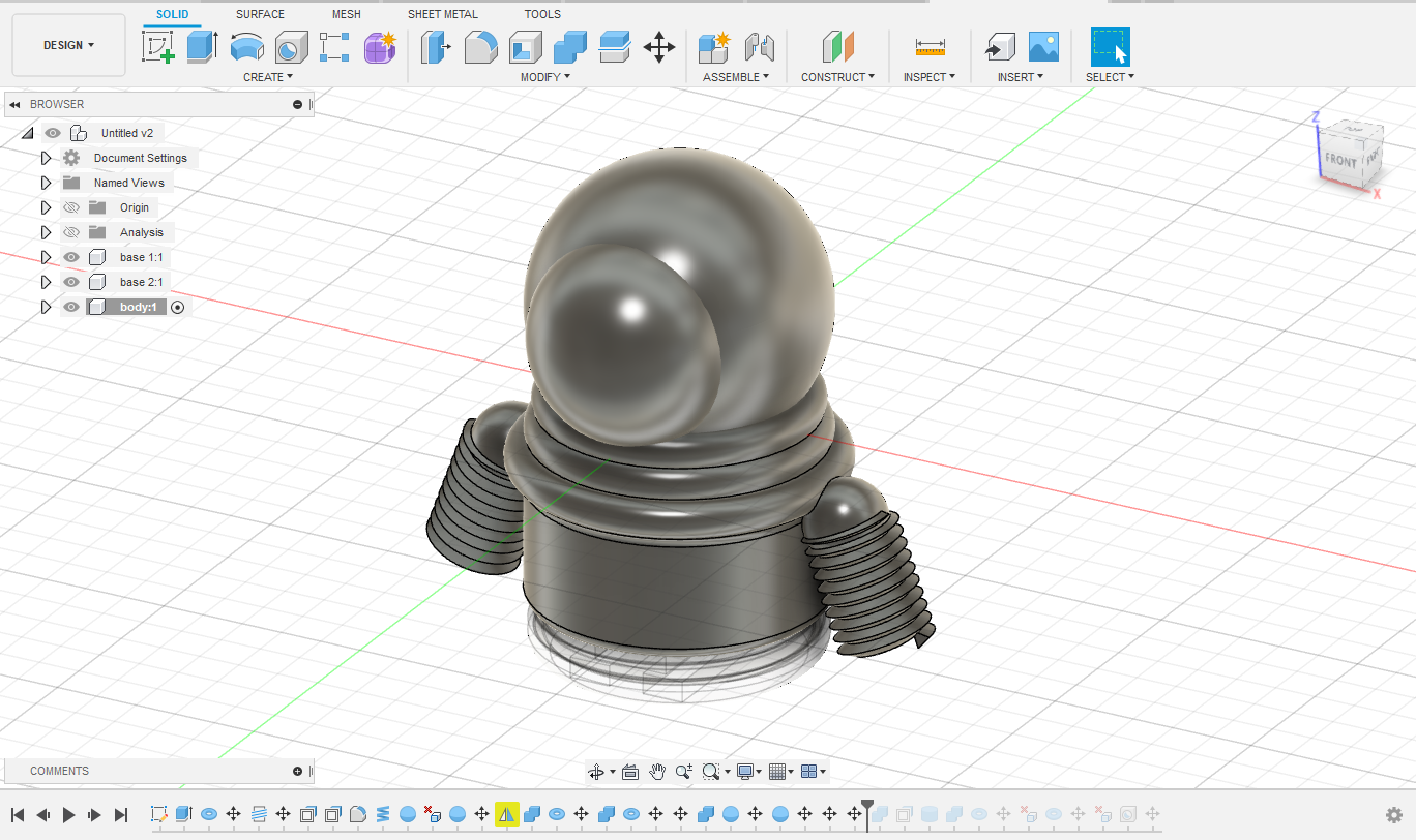
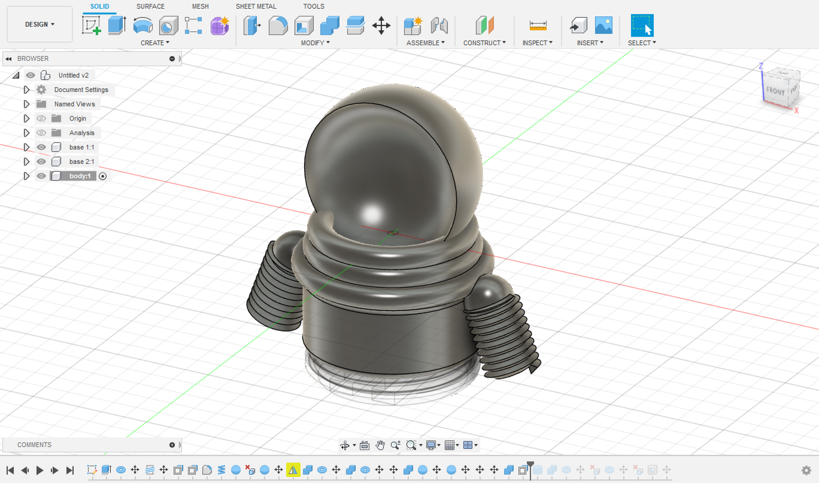
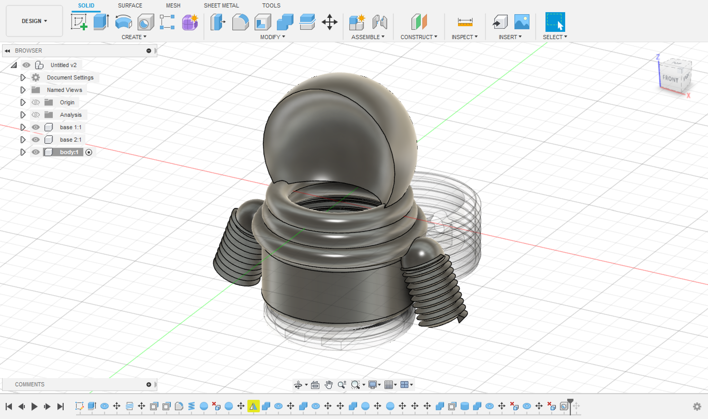
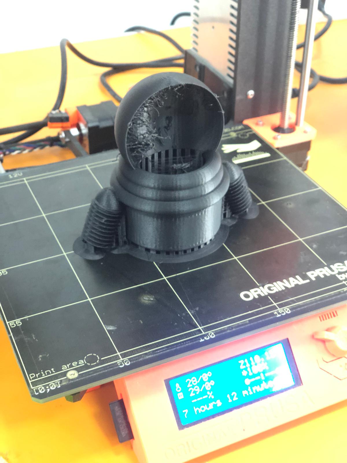
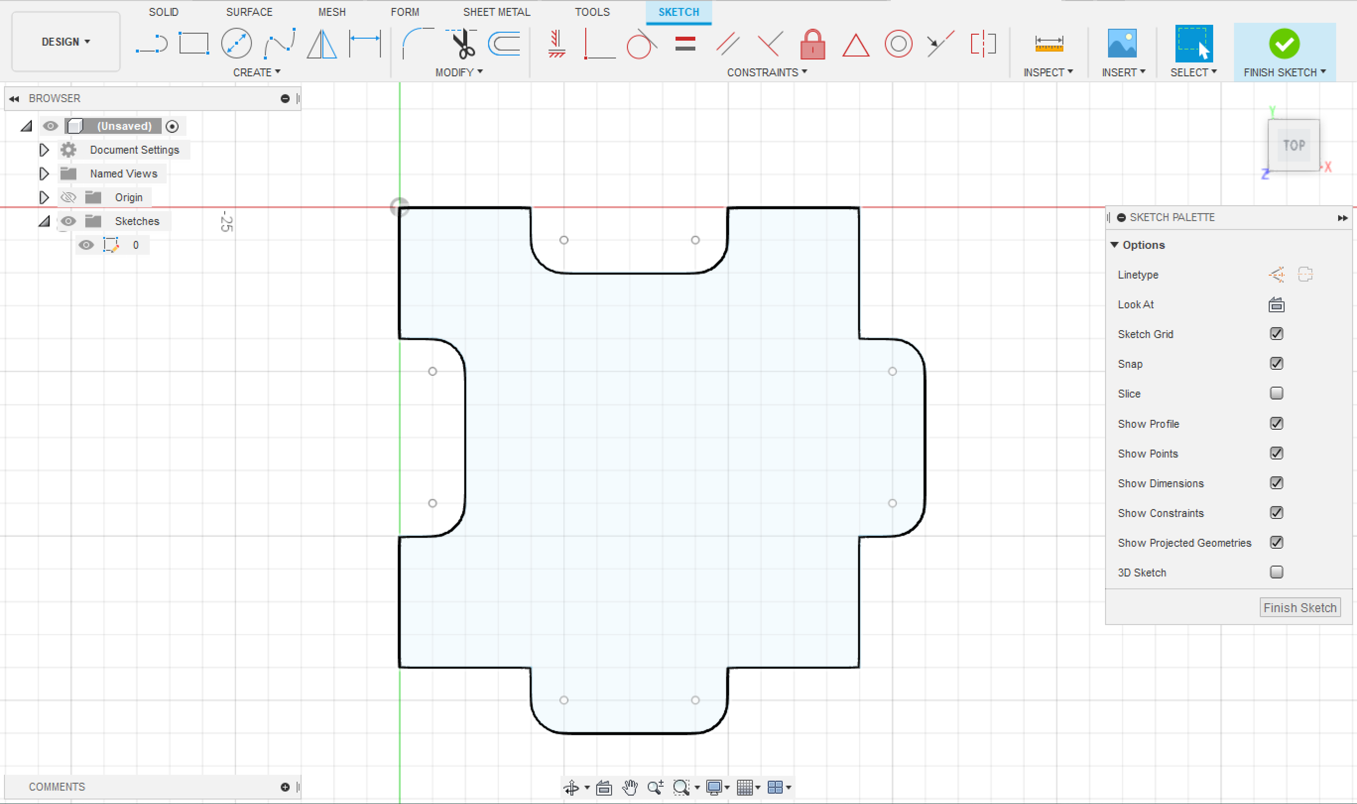
After knowing everything I need to include in my design for the piece, I then started the process of designing it and printing it.
I used Fuion360 for the design, and I did it from scratch.
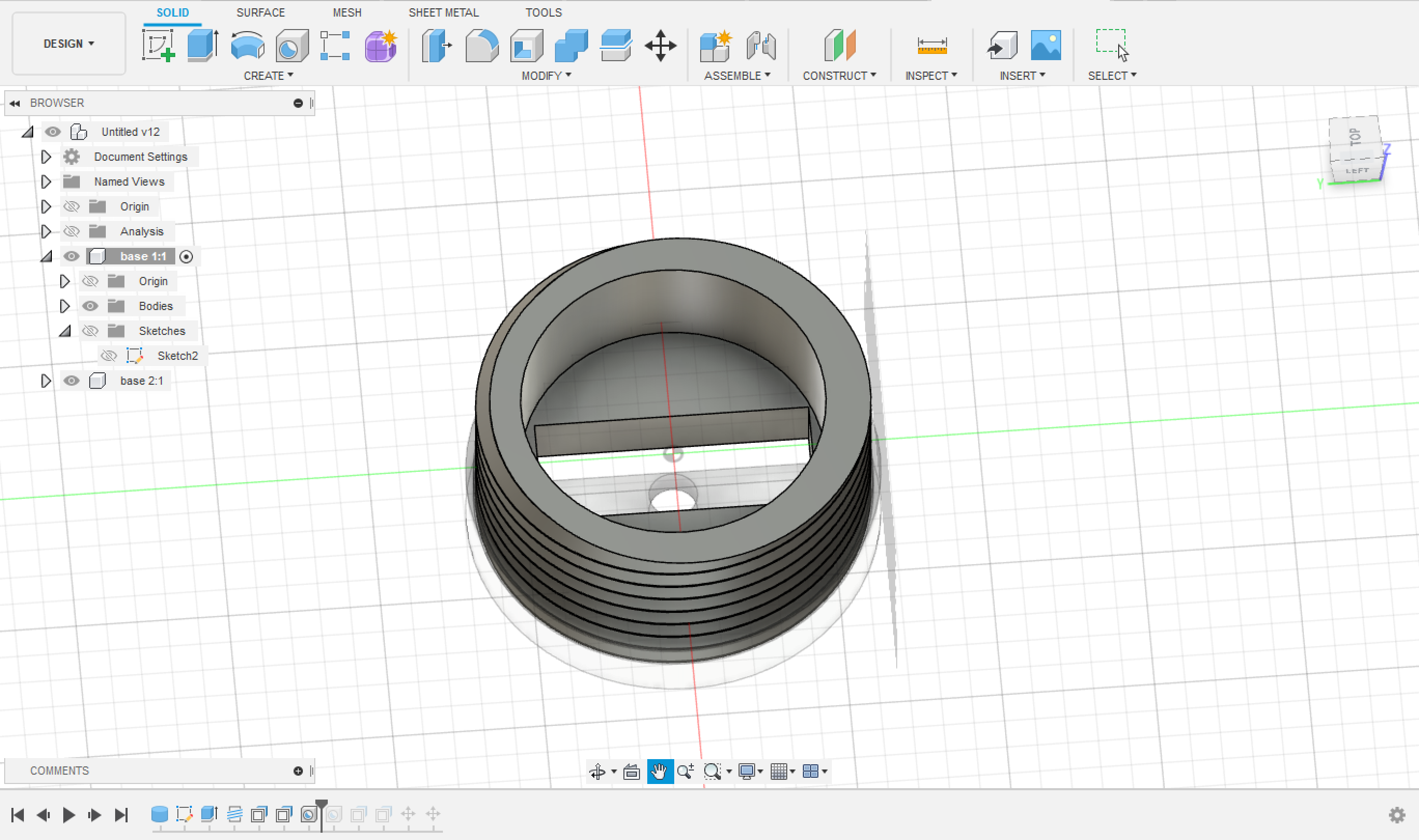
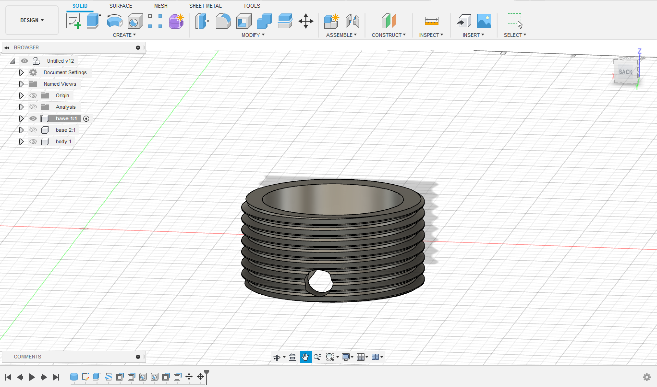
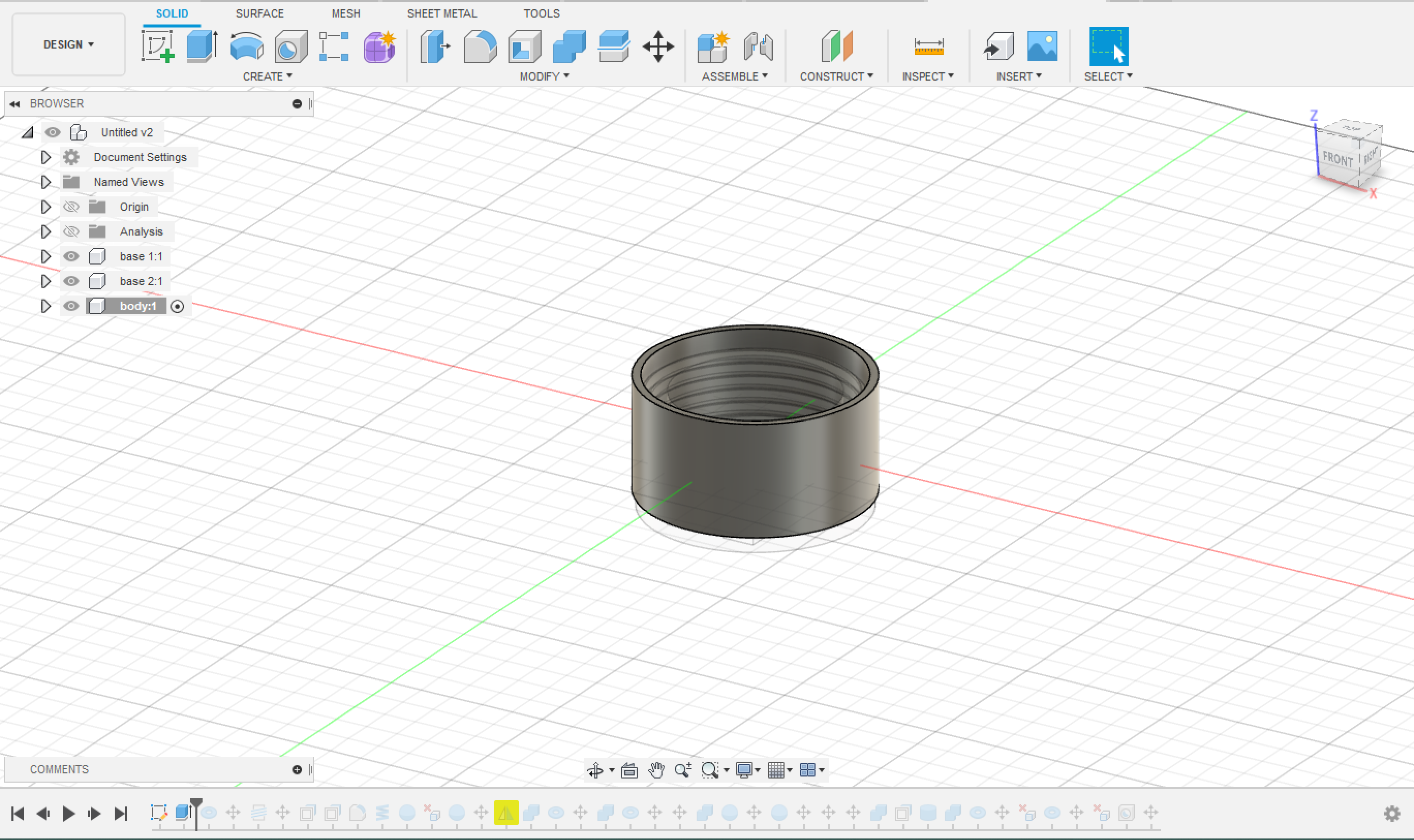
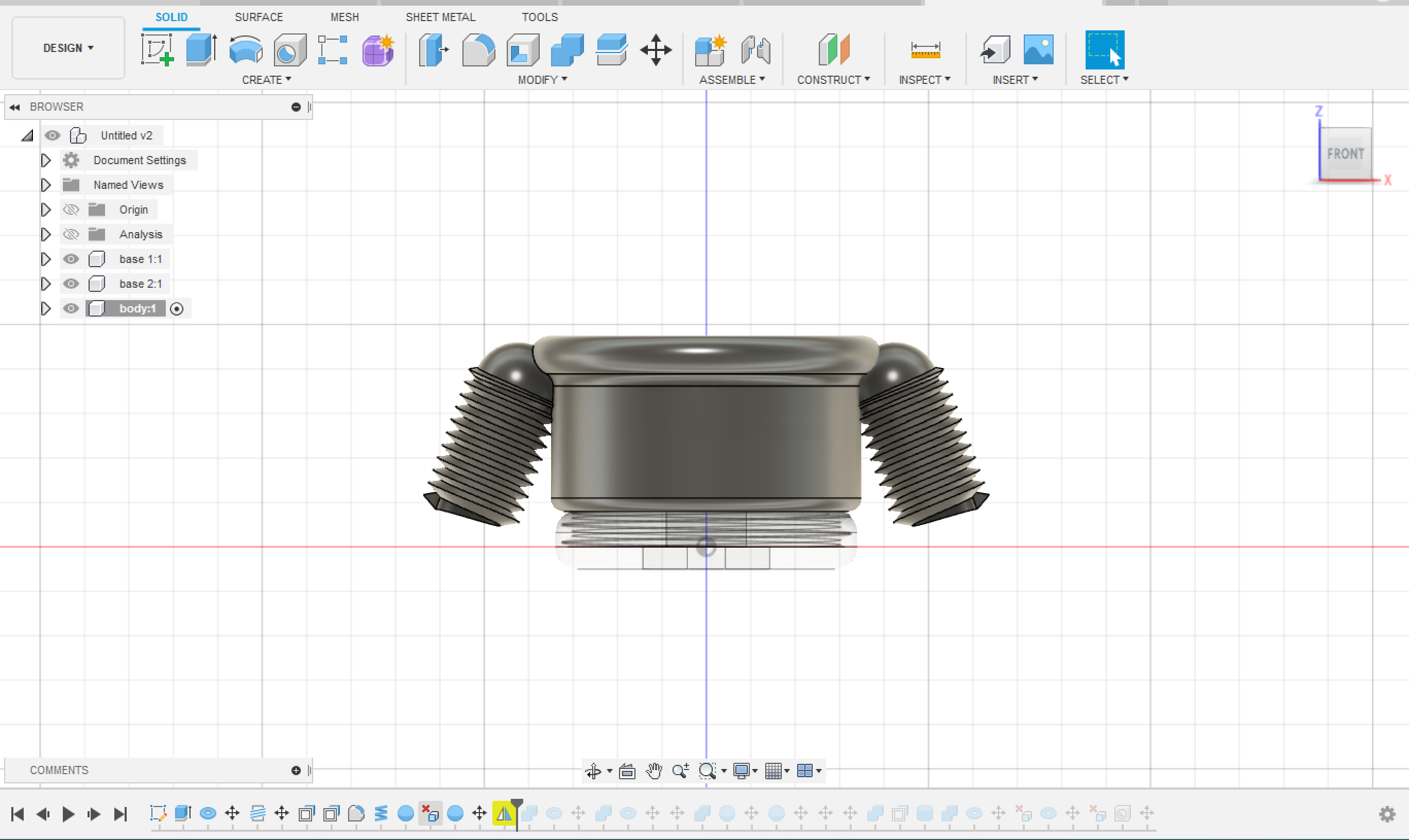
The design consists of three parts:
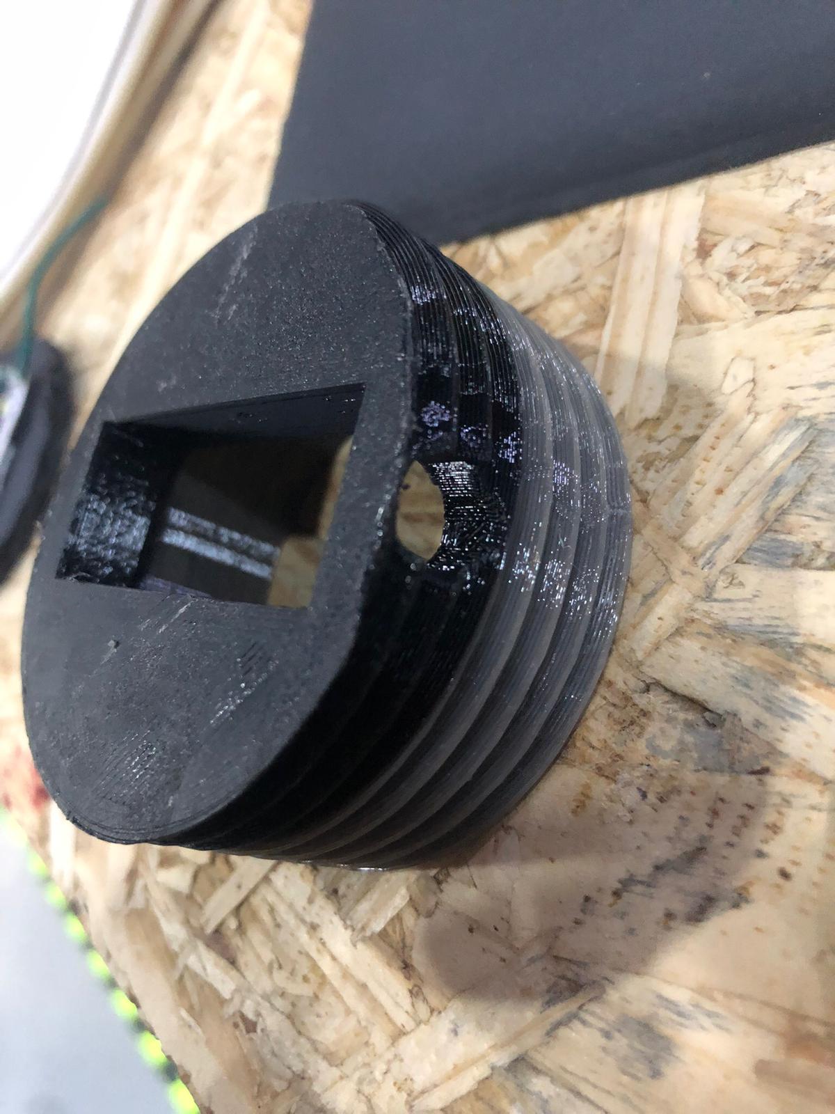
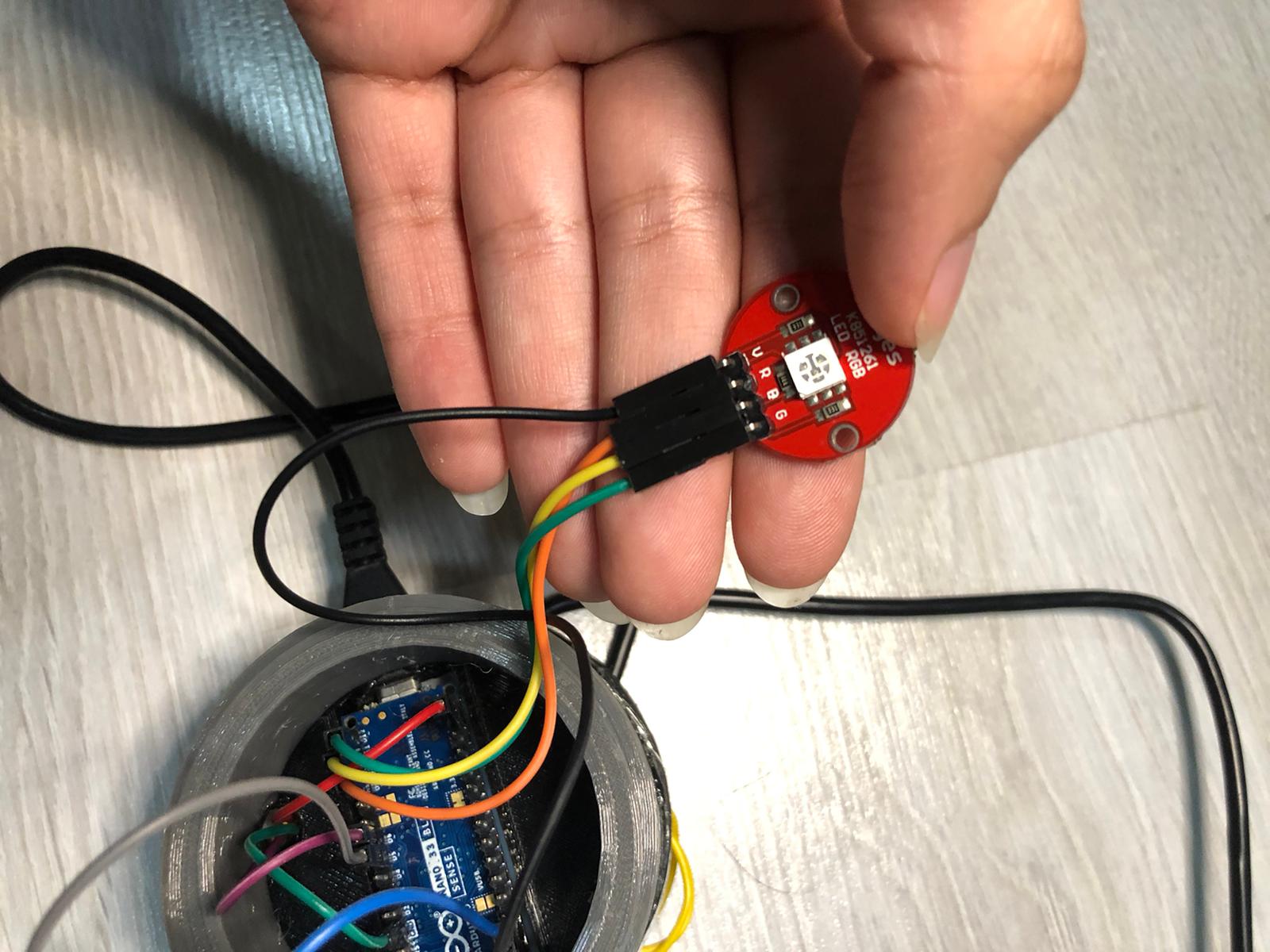
The 1st Base which holds on the Arduino, and it is tighten to the body and the 2nd base. It must have a hole for the USB wire and must be empty for the wires to be connected in the Pinouts of the Arduino.
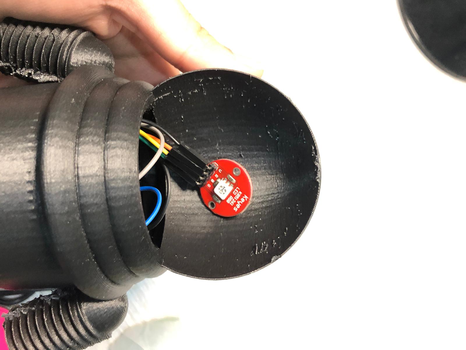
The 2nd Base which tightens up to the 1st base, and has a placement for LED Strips. It must have a place for the wires of the LED strips to go all the way up and be connected to the pinouts of the Arduino.
The Body which tighten up to the 1st base and basically it is the shape of the piece. It must be empty from the inside.
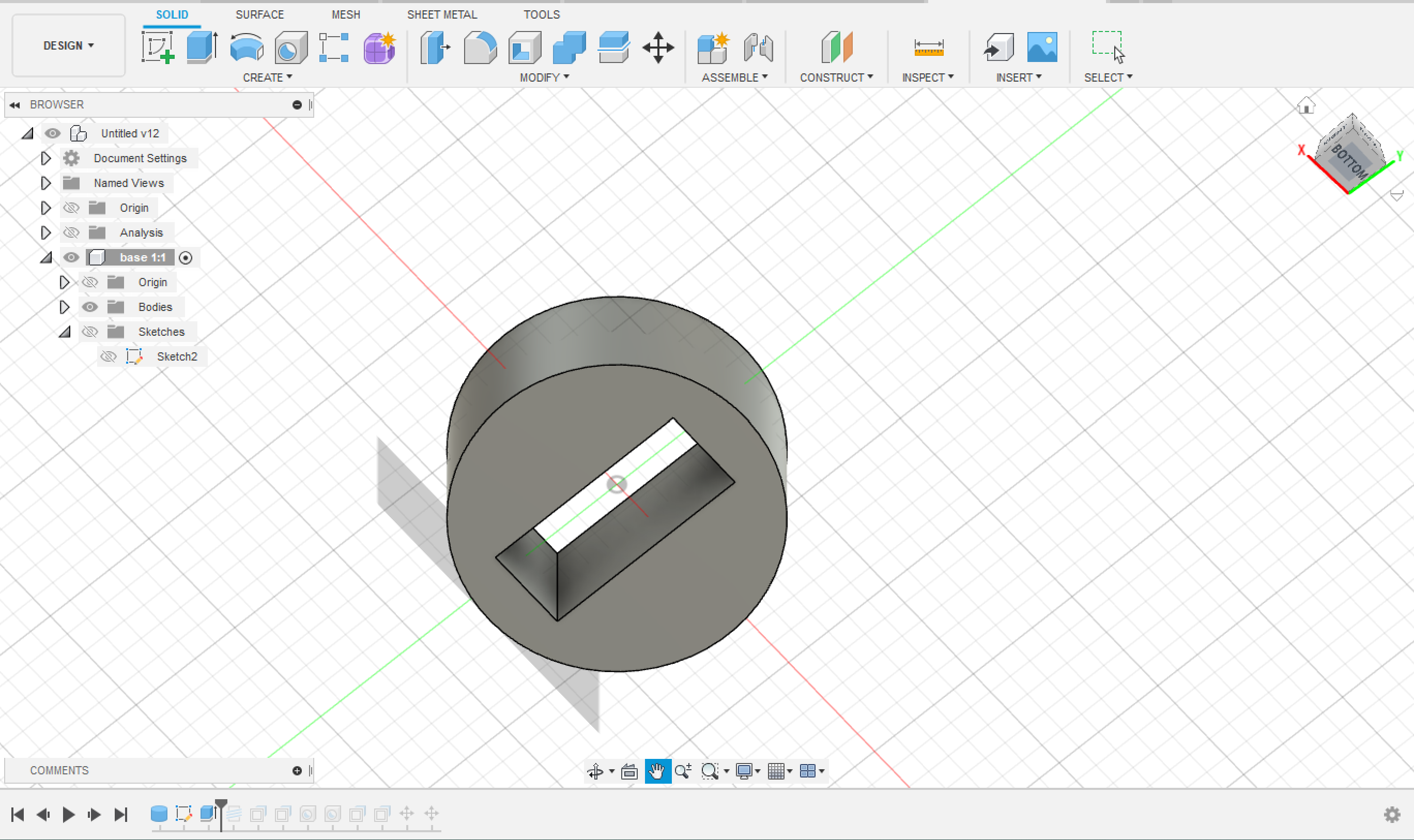
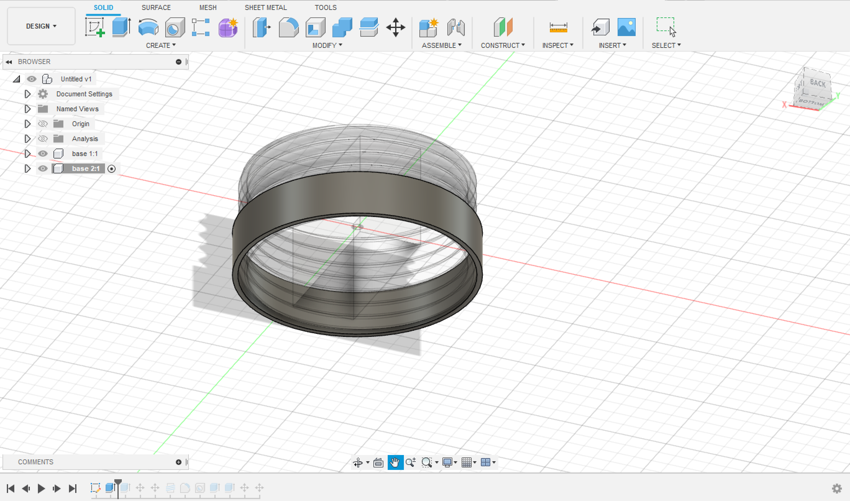
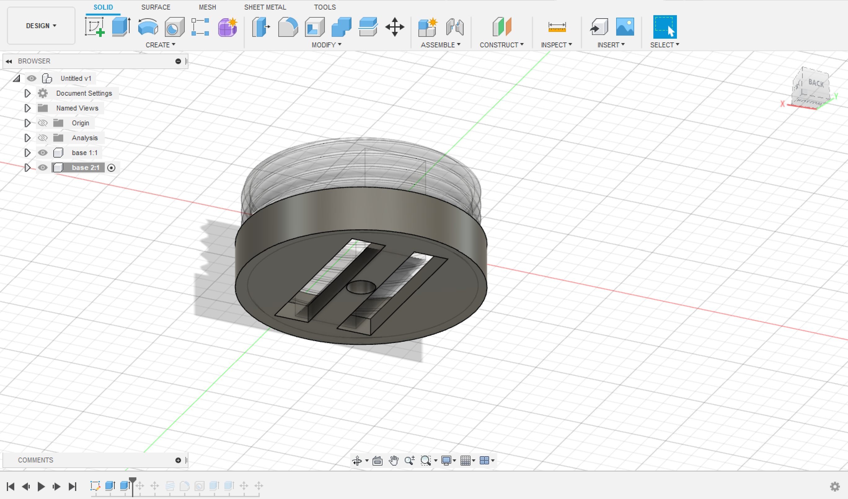

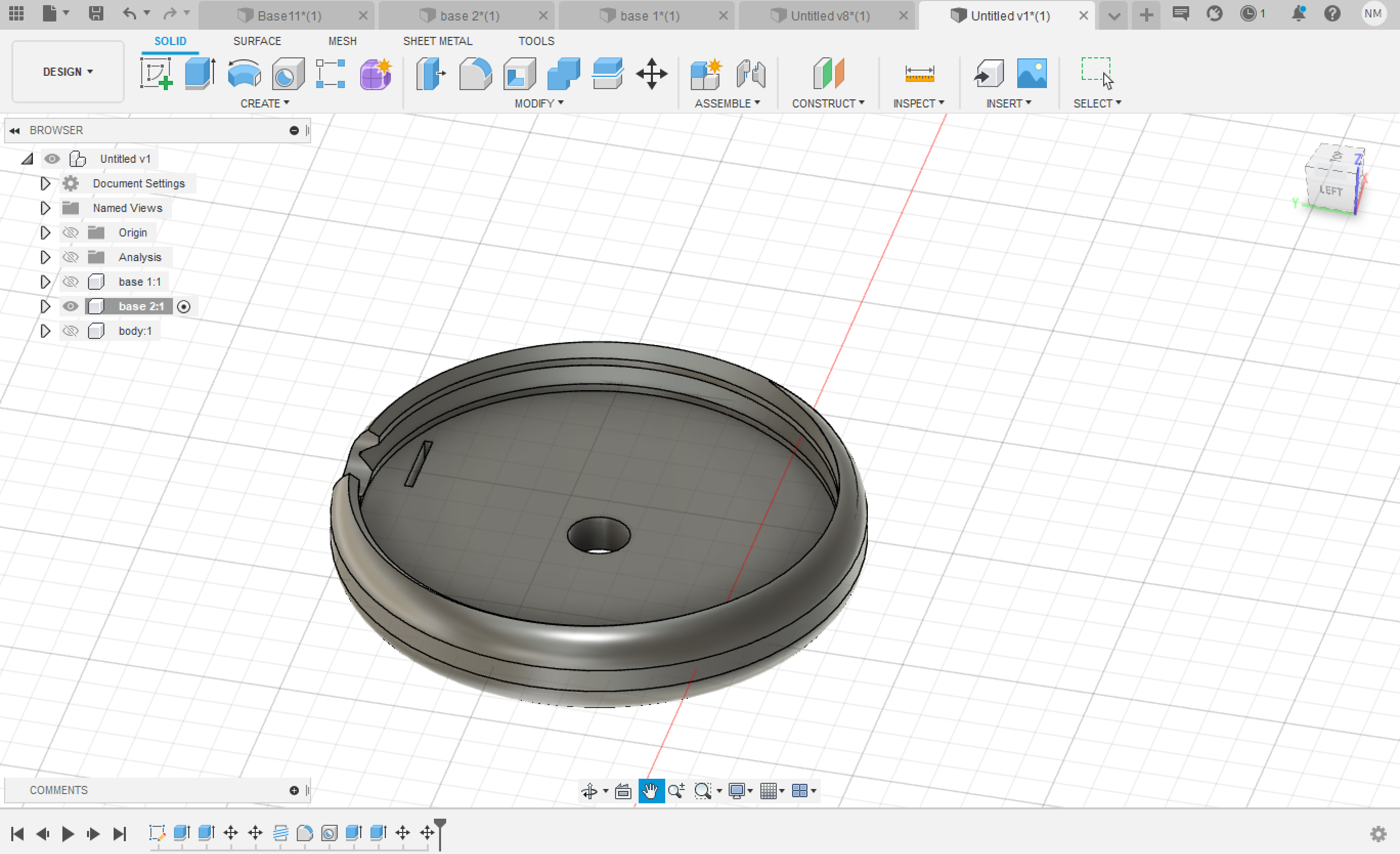
The final design of the 2nd Base is as seen:
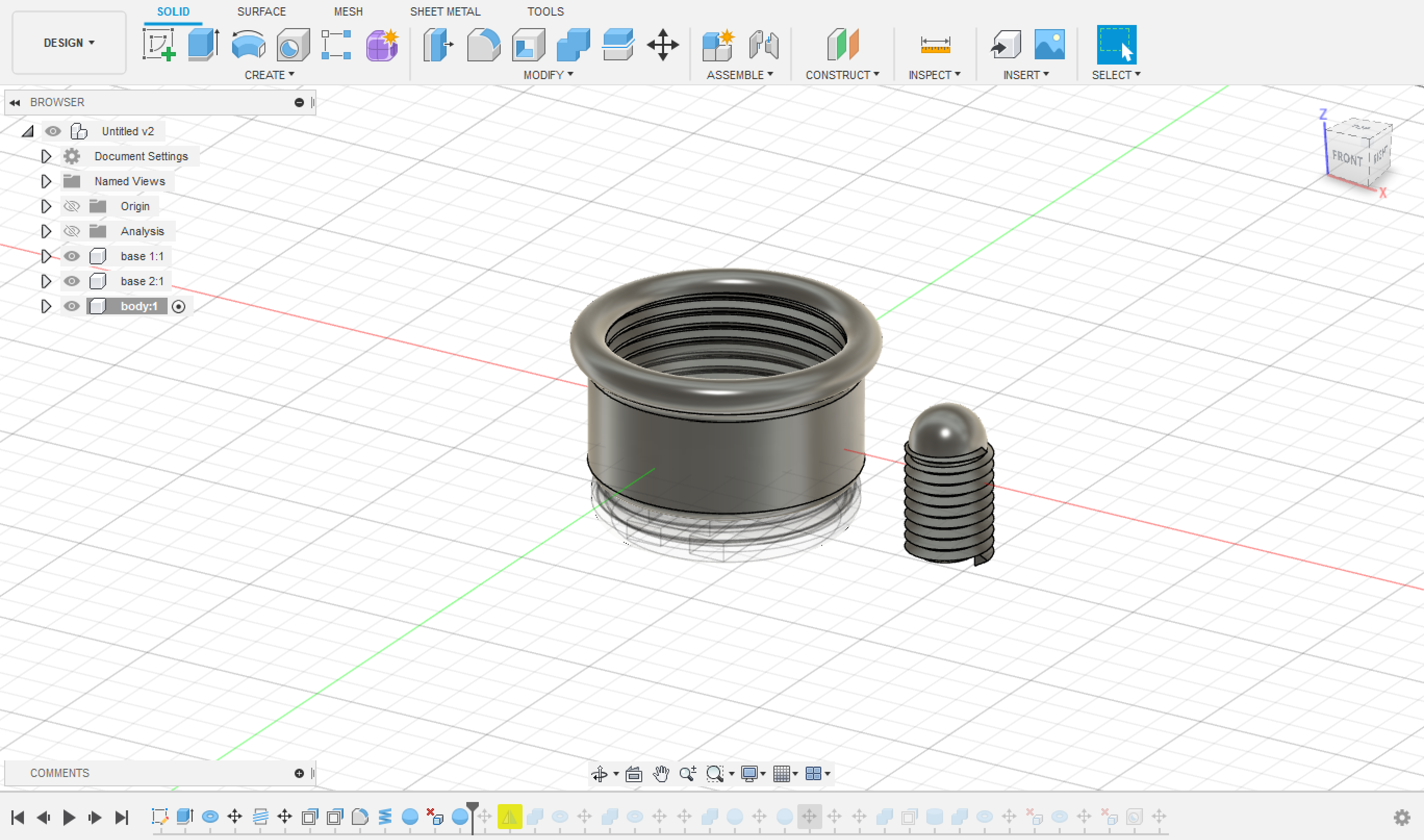

The 3 parts were 3D printed using Prusa i3 MK3S
I did the slicing in Ultimaker Cura; for further reading about the printer settings and how to 3D print Read This Page
The design then was cut using a laser cutter, on different colored cardboards of height ~ 15mm.
To know more about the laser cutting process and the setting of the machine Read This Page
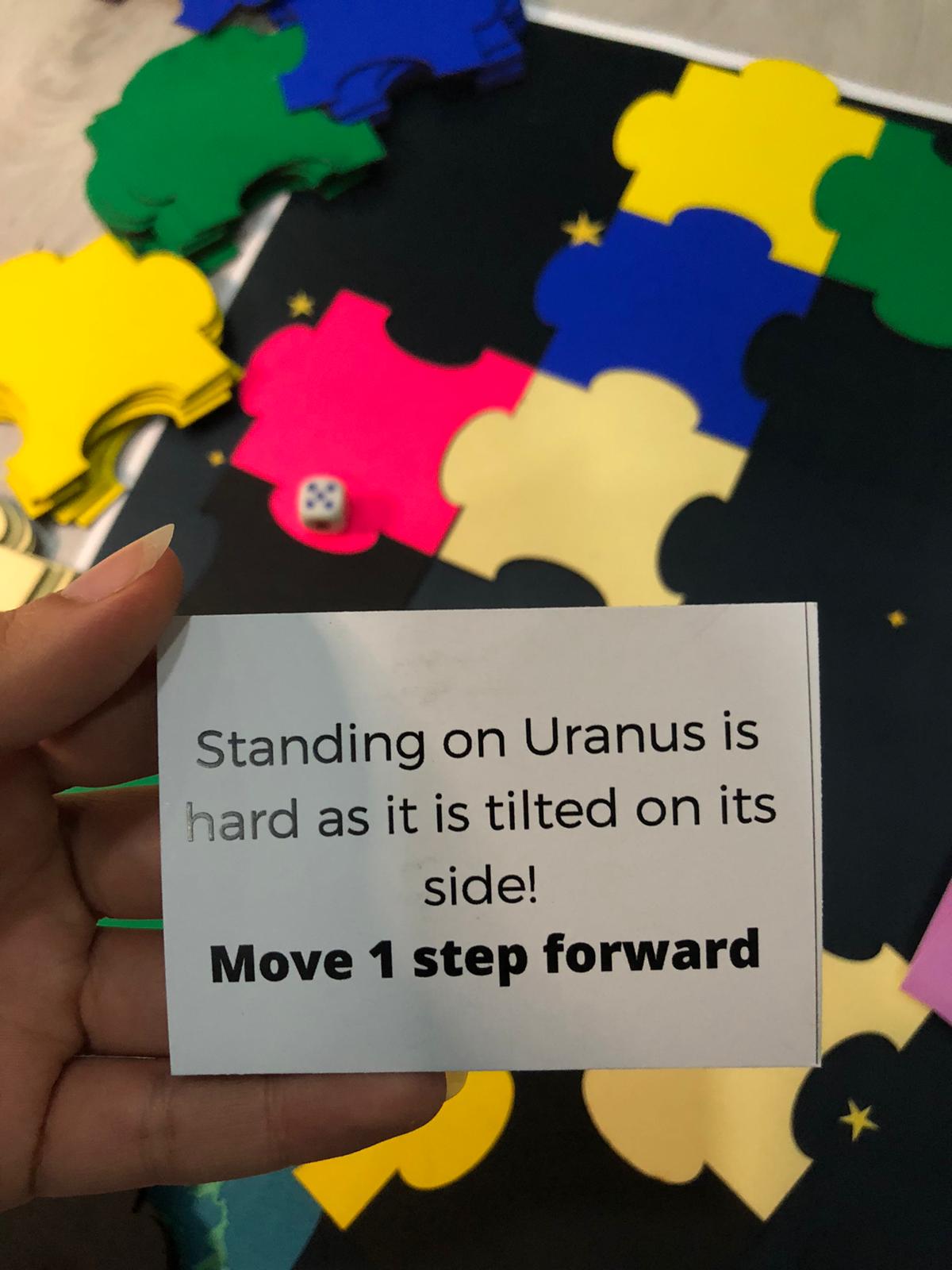
To download the file for the cards designs and the instructions see below.
Make sure to print the cards correctly as they are two-sided.
The electronic parts of this project are:
Wires for connections.
The electronic parts were connected as seen in the figure below:
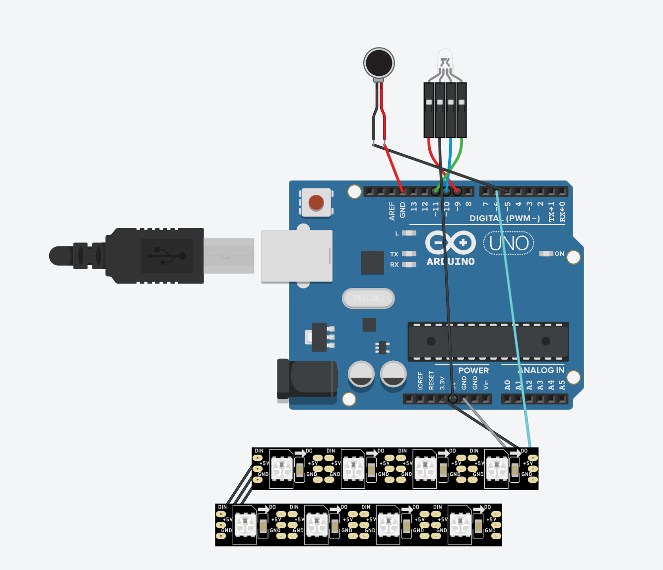
Simulation is done by TnkerCAD Note that Arduino Nano 33 BLE Sense was used in this project and not UNO.
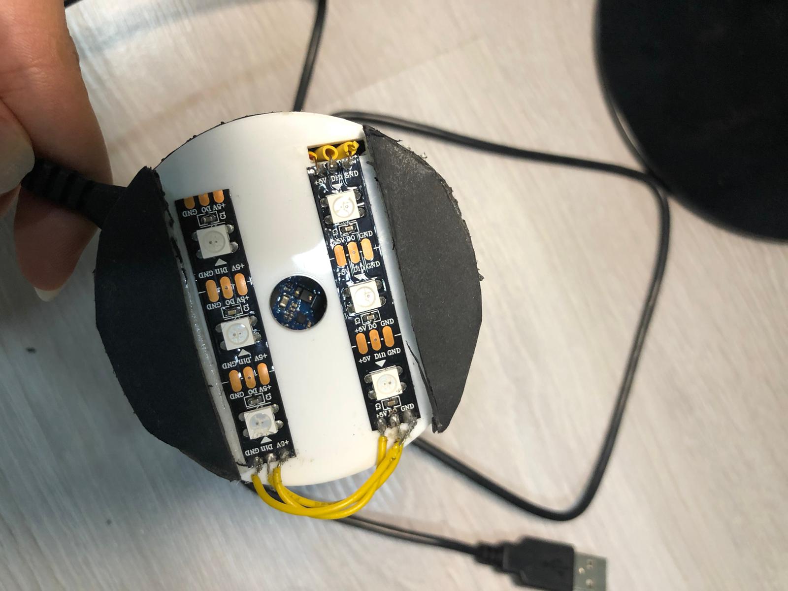
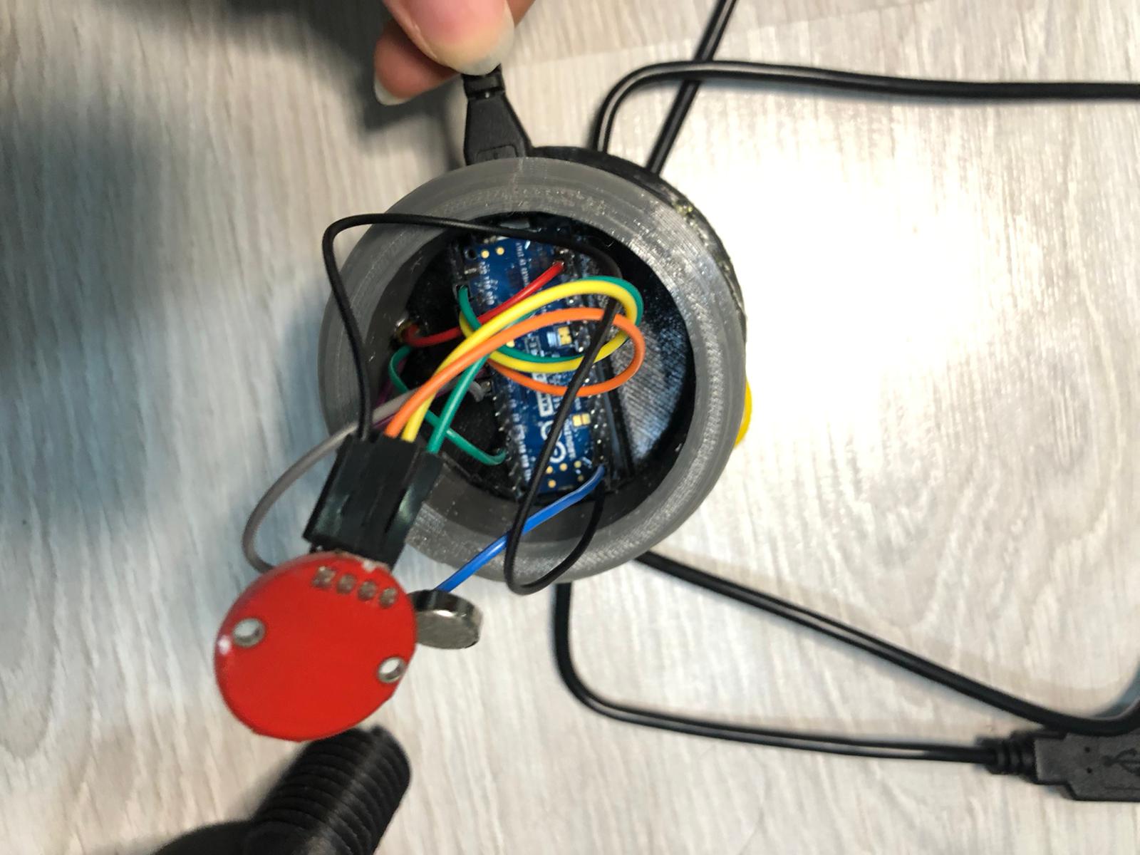
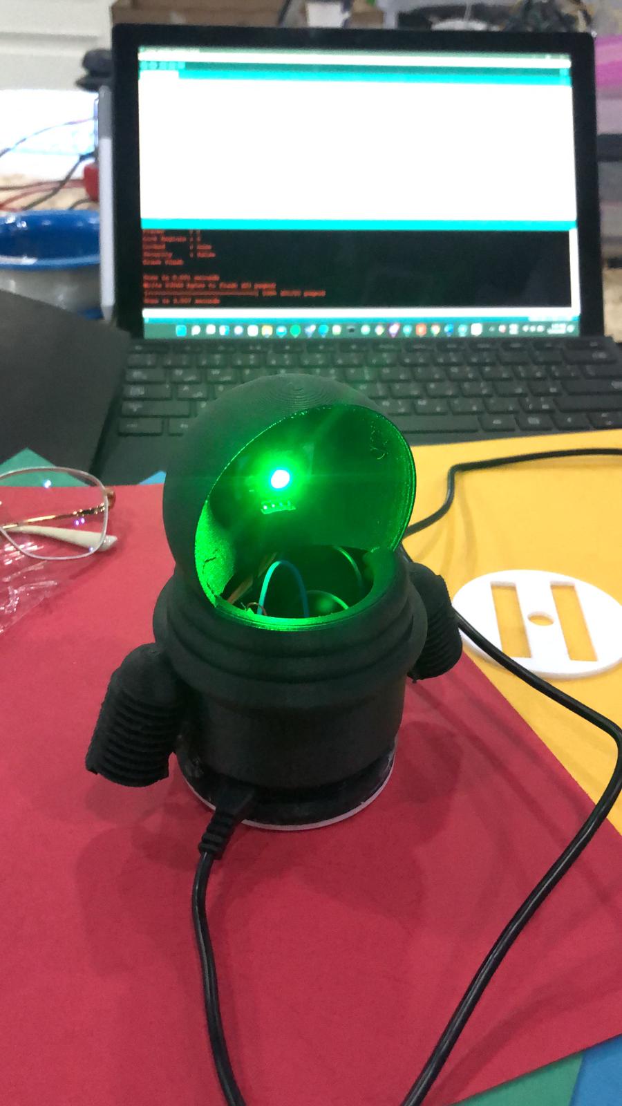
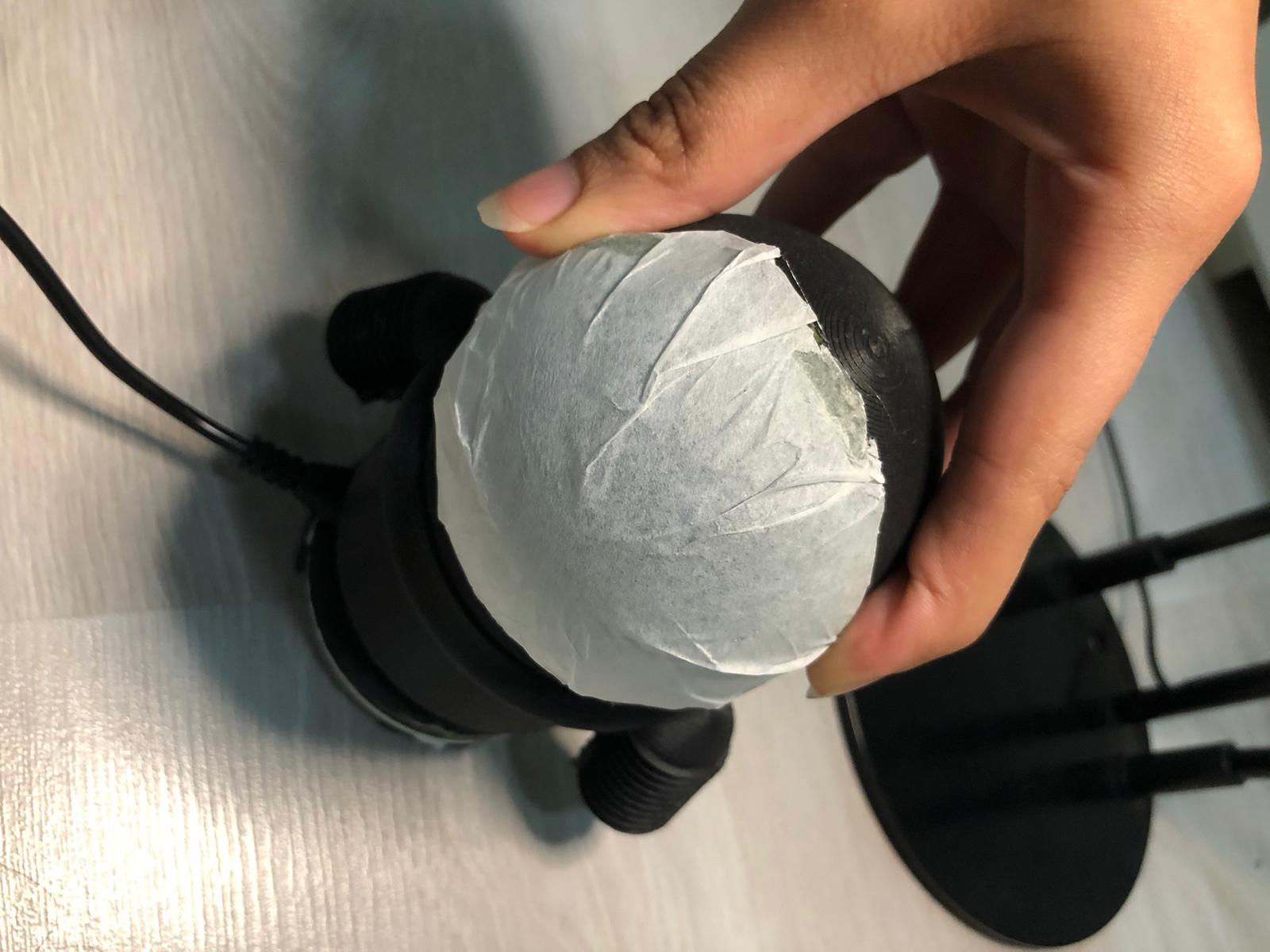
Now place the body part on top to cover all the electronics.
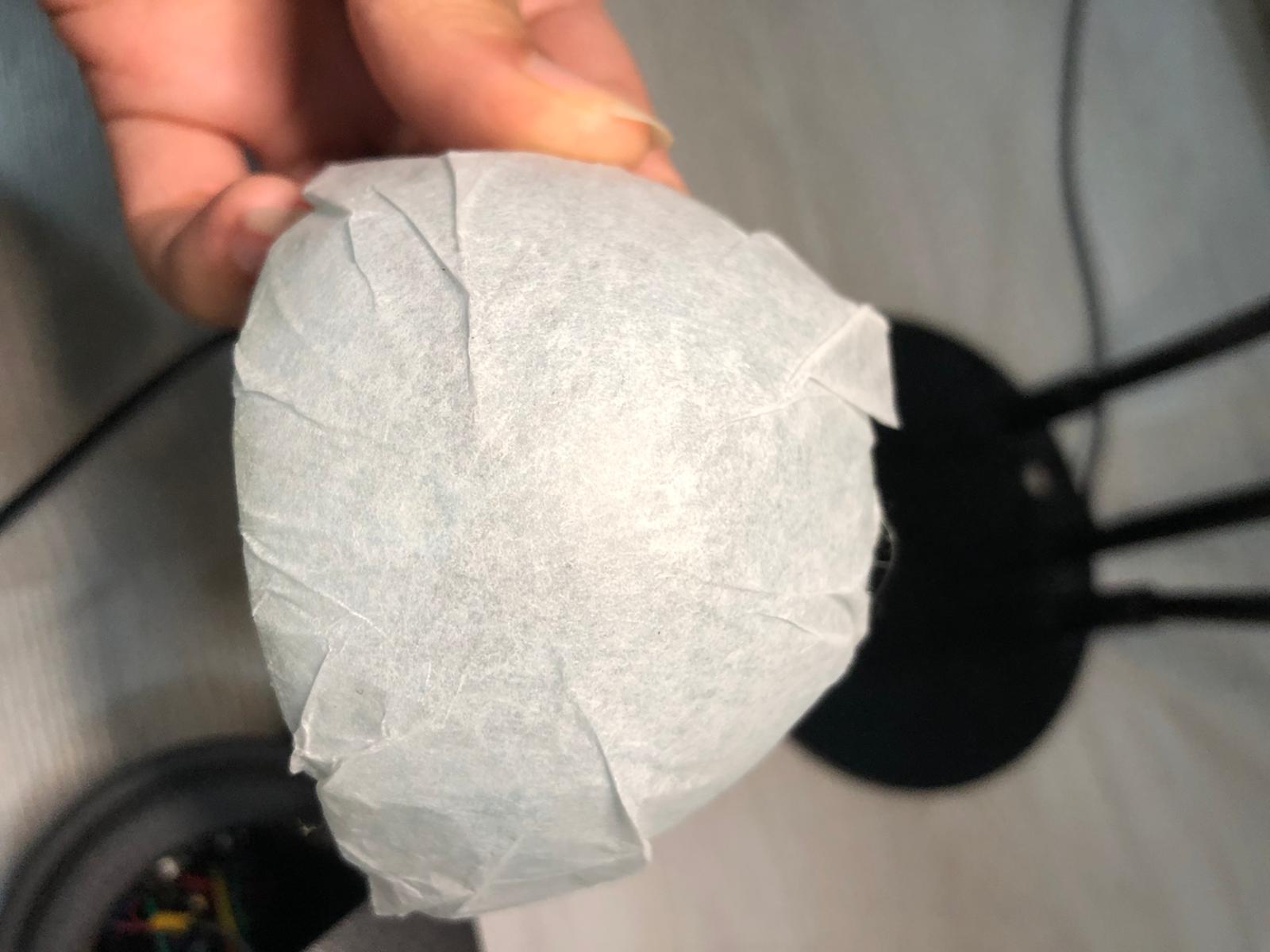
Make sure that the cords of the LED RGB are long enough for it to stick on the inside of the helmet of the astronaut.
The code of the game is as follows:
											// SENSOR LIBRARY
											#include <Arduino_APDS9960.h>

											//ADDRESSABLE RGB LED LIBRARY
											#include <Adafruit_NeoPixel.h>

											#ifdef __AVR__
											 #include <avr/power.h> // Required for 16 MHz Adafruit Trinket
											#endif
											// Which pin on the Arduino is connected to the NeoPixels?
											#define PIN        6 // LED PIN
											// How many NeoPixels are attached to the Arduino?
											#define NUMPIXELS 6 // Popular NeoPixel ring size
											Adafruit_NeoPixel pixels(NUMPIXELS, PIN, NEO_GRB + NEO_KHZ800);

											#define DELAYVAL 500 // Time (in milliseconds) to pause between pixels

											void setup() {

											#if defined(__AVR_ATtiny85__) && (F_CPU == 16000000)
											  clock_prescale_set(clock_div_1);
											#endif
											  // END of Trinket-specific code.

											  pixels.begin(); // INITIALIZE NeoPixel strip object (REQUIRED)

											  Serial.begin(9600);
											  while (!Serial);

											  if (!APDS.begin()) {
												Serial.println("Error initializing APDS-9960 sensor.");
											  }


												 pinMode(6, OUTPUT); //LED LIGHT (BASE)
												 pinMode(9, OUTPUT); // RED
												 pinMode(10, OUTPUT); //BLUE
												 pinMode(11, OUTPUT); //GREEN
												 pinMode(5, OUTPUT); //PUZZER


											}

											void loop() {


											  int r, g, b, a;
											  double rh, bh, gh, cmax, cmin, del, h, hf;

											  // read the color
											  APDS.readColor(r, g, b);

											  // print the values
											  Serial.print("r = ");
											  Serial.println(r);
											  Serial.print("g = ");
											  Serial.println(g);
											  Serial.print("b = ");
											  Serial.println(b);
											  Serial.println();

												// wait a bit before reading again
											  delay(500);


											  // LOWER LGB
											  pixels.clear(); // Set all pixel colors to 'off'

											  // The first NeoPixel in a strand is #0, second is 1, all the way up
											  // to the count of pixels minus one.
											  //for(int i=0; i<NUMPIXELS; i++) { // For each pixel...

												// pixels.Color() takes RGB values, from 0,0,0 up to 255,255,255

												pixels.setPixelColor(0, pixels.Color(255, 255, 255));
												pixels.setPixelColor(2,  pixels.Color(255, 255, 255));
												pixels.setPixelColor(3,  pixels.Color(255, 255, 255));
												pixels.setPixelColor(5,  pixels.Color(255, 255, 255));

												pixels.show();   // Send the updated pixel colors to the hardware.

												//delay(DELAYVAL); // Pause before next pass through loop
											  //}


											// SENSOR
											 // check if a color reading is available
											  while (! APDS.colorAvailable()) {
												delay(1);
											  }


											  //find new r,g,b,c,del
											  //rh=r/255;
											 // gh=g/255;
											  //bh=b/255;
											  cmax= max(r,g);
											  cmax= max(cmax,b);

											  cmin=min(r,g);
											  cmin= min(cmin,b);

											  del= (cmax-cmin);

											   // find HUE

											 if (r>g & r>b)
											  {h=60*((g-b)/del);}

											  if (g>r & g>b)
											  {h= 60*((b-r)/del+2);}

											  if (b>r & b>g)
											  {h=60*((r-g)/del+4);}

											if (h<0)
											{h=h+360;}

											  Serial.println();
											  Serial.println(h);
											  Serial.println();

											//GAME SETTINGS
											// depending on the value of h, the output led will change colors or the puzzer will turn on
											// REFRENCE FOR HUE VALUES FOR THE PIECES OF BLUE HOME GAME:

											while ( abs(h-hf) > 5.0)
											{
											// PINK
											if (h>220 & h <360)
											{
											  a= random(1,3);
											  }

											  //BLUE
											if (h<220 & h >210)
											{
												a= random(3,4);
											  }

											//BLACK
											if (h>180 & h <210)
											{
											  a=random(4,6);
											  }

											//GREEN
											if (h<180 & h >140)
											 {
											  a =random(1,3);
											  }

											  //OFFWHITE
											if (h<140 & h >40)
											{
											  a= random(4,8);
											  }

											 //YELLOW
											if (h<40 & h >0)
											{
											  a =random(3,5);
											  }

											//////////////////

											  if (a==1)
											{
											 digitalWrite(5, LOW ); // Turn the VIBRATING on
											 digitalWrite(9, LOW ); // RED
											 digitalWrite(10, LOW ); // BLUE
											 digitalWrite(11, HIGH ); //GREEN
											}

											if (a==2)

											{ digitalWrite(5, LOW ); // Turn the VIBRATING on
											 digitalWrite(9, HIGH ); // RED
											 digitalWrite(10, LOW ); // BLUE
											 digitalWrite(11, LOW ); //GREEN
											}

											if ( a==3)
											{
											 digitalWrite(5, LOW ); // Turn the VIBRATING on
											 digitalWrite(9, HIGH ); // RED
											 digitalWrite(10, LOW ); // BLUE
											 digitalWrite(11, LOW ); //GREEN
											 }


											if (a==4)
											{
											 digitalWrite(5, HIGH ); // Turn the VIBRATING on
											 digitalWrite(9, LOW ); // RED
											 digitalWrite(10, LOW ); // BLUE
											 digitalWrite(11, LOW ); //GREEN
											 }


											if (a==5)
											{
											 digitalWrite(5, LOW ); // Turn the VIBRATING on
											 digitalWrite(9, HIGH ); // RED
											 digitalWrite(10, HIGH ); // BLUE
											 digitalWrite(11, LOW ); //GREEN
											 }


											if (a==6)
											{
											 digitalWrite(5, HIGH ); // Turn the VIBRATING on
											 digitalWrite(9, LOW ); // RED
											 digitalWrite(10, HIGH ); // BLUE
											 digitalWrite(11, HIGH ); //GREEN
											 }


											if (a==7)
											{
											 digitalWrite(5, LOW ); // Turn the VIBRATING on
											 digitalWrite(9, LOW ); // RED
											 digitalWrite(10, HIGH ); // BLUE
											 digitalWrite(11, LOW ); //GREEN
											 }

											 hf = h;
											}


											  Serial.print("hf = ");
											  Serial.println(hf);
											  Serial.println();

											}
The code runs the LED in the base to light up the area under the piece so it is visible for the Arduino Built-In sensor, this LED is turned on through out the game.
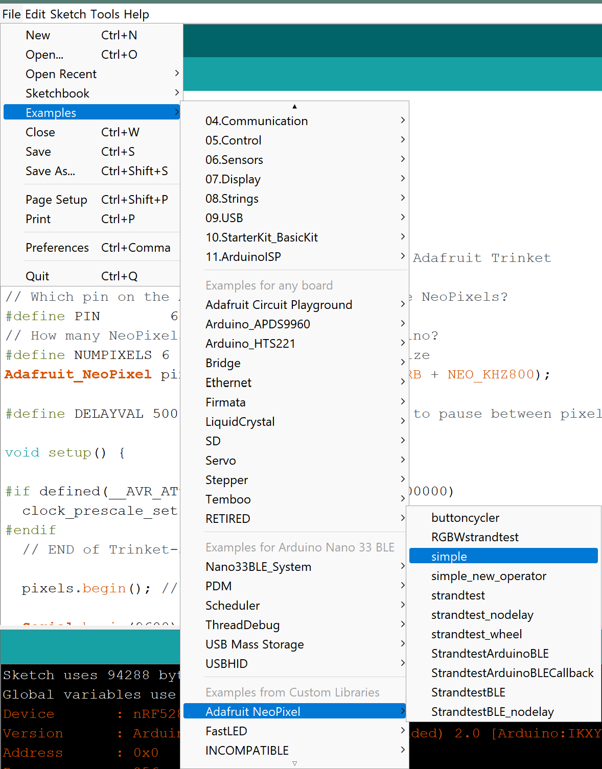
Note that the library for the addressable RGB LED strips is needed to be downloaded and included in the code. Adafruit NeoPixel Library
The Simple example helped me understand how to program the LED Strips, As they are vey bright I ended up using only 4 out of 6 LEDs.
The RGB sensor's library needs to be included in the code, the library is APDS9960.
The sensor reads values of RGB and then using equations convert them to a single value which is hue (h).
Then this value is compared to the previous calculated value of hue, and if there is a difference (meaning the piece has moved) then the piece will randomly react depending on the color it sensed.
The reaction is the change of the head's color (White/Red/Pink/Cyan/Yellow/Green) or a vibration.
A useful page to understand how RGB sensor works here
// NeoPixel Ring simple sketch (c) 2013 Shae Erisson
											// Released under the GPLv3 license to match the rest of the
											// Adafruit NeoPixel library

											#include <Adafruit_NeoPixel.h>
											#ifdef __AVR__
											 #include <avr/power.h> // Required for 16 MHz Adafruit Trinket
											#endif

											// Which pin on the Arduino is connected to the NeoPixels?
											#define PIN        6 // On Trinket or Gemma, suggest changing this to 1

											// How many NeoPixels are attached to the Arduino?
											#define NUMPIXELS 16 // Popular NeoPixel ring size

											// When setting up the NeoPixel library, we tell it how many pixels,
											// and which pin to use to send signals. Note that for older NeoPixel
											// strips you might need to change the third parameter -- see the
											// strandtest example for more information on possible values.
											Adafruit_NeoPixel pixels(NUMPIXELS, PIN, NEO_GRB + NEO_KHZ800);

											#define DELAYVAL 500 // Time (in milliseconds) to pause between pixels

											void setup() {
											  // These lines are specifically to support the Adafruit Trinket 5V 16 MHz.
											  // Any other board, you can remove this part (but no harm leaving it):
											#if defined(__AVR_ATtiny85__) && (F_CPU == 16000000)
											  clock_prescale_set(clock_div_1);
											#endif
											  // END of Trinket-specific code.

											  pixels.begin(); // INITIALIZE NeoPixel strip object (REQUIRED)
											}

											void loop() {
											  pixels.clear(); // Set all pixel colors to 'off'

											  // The first NeoPixel in a strand is #0, second is 1, all the way up
											  // to the count of pixels minus one.
											  for(int i=0; i<NUMPIXELS; i++) { // For each pixel...

												// pixels.Color() takes RGB values, from 0,0,0 up to 255,255,255
												// Here we're using a moderately bright green color:
												pixels.setPixelColor(i, pixels.Color(0, 150, 0));

												pixels.show();   // Send the updated pixel colors to the hardware.

												delay(DELAYVAL); // Pause before next pass through loop
											  }
											}
/*
											  APDS-9960 - Color Sensor

											  This example reads color data from the on-board APDS-9960 sensor of the
											  Nano 33 BLE Sense and prints the color RGB (red, green, blue) values
											  to the Serial Monitor once a second.

											  The circuit:
											  - Arduino Nano 33 BLE Sense

											  This example code is in the public domain.
											*/

											#include <Arduino_APDS9960.h>

											void setup() {
											  Serial.begin(9600);
											  while (!Serial);

											  if (!APDS.begin()) {
												Serial.println("Error initializing APDS-9960 sensor.");
											  }
											}

											void loop() {
											  // check if a color reading is available
											  while (! APDS.colorAvailable()) {
												delay(5);
											  }
											  int r, g, b;

											  // read the color
											  APDS.readColor(r, g, b);

											  // print the values
											  Serial.print("r = ");
											  Serial.println(r);
											  Serial.print("g = ");
											  Serial.println(g);
											  Serial.print("b = ");
											  Serial.println(b);
											  Serial.println();

											  // wait a bit before reading again
											  delay(1000);
											}
											// SENSOR LIBRARY
											#include <Arduino_APDS9960.h>

											//ADDRESSABLE RGB LED LIBRARY
											#include <Adafruit_NeoPixel.h>

											#ifdef __AVR__
											 #include <avr/power.h> // Required for 16 MHz Adafruit Trinket
											#endif
											// Which pin on the Arduino is connected to the NeoPixels?
											#define PIN        6 // LED PIN
											// How many NeoPixels are attached to the Arduino?
											#define NUMPIXELS 6 // Popular NeoPixel ring size
											Adafruit_NeoPixel pixels(NUMPIXELS, PIN, NEO_GRB + NEO_KHZ800);

											#define DELAYVAL 500 // Time (in milliseconds) to pause between pixels

											void setup() {

											#if defined(__AVR_ATtiny85__) && (F_CPU == 16000000)
											  clock_prescale_set(clock_div_1);
											#endif
											  // END of Trinket-specific code.

											  pixels.begin(); // INITIALIZE NeoPixel strip object (REQUIRED)

											  Serial.begin(9600);
											  while (!Serial);

											  if (!APDS.begin()) {
												Serial.println("Error initializing APDS-9960 sensor.");
											  }


												 pinMode(6, OUTPUT); //LED LIGHT (BASE)
												 pinMode(9, OUTPUT); // RED
												 pinMode(10, OUTPUT); //BLUE
												 pinMode(11, OUTPUT); //GREEN
												 pinMode(5, OUTPUT); //PUZZER


											}

											void loop() {


											  int r, g, b;
											  double rh, bh, gh, cmax, cmin, del, h;

											  // read the color
											  APDS.readColor(r, g, b);

											  // print the values
											  Serial.print("r = ");
											  Serial.println(r);
											  Serial.print("g = ");
											  Serial.println(g);
											  Serial.print("b = ");
											  Serial.println(b);
											  Serial.println();

												// wait a bit before reading again
											  delay(500);


											  // LOWER LGB
											  pixels.clear(); // Set all pixel colors to 'off'

											  // The first NeoPixel in a strand is #0, second is 1, all the way up
											  // to the count of pixels minus one.
											  //for(int i=0; i<NUMPIXELS; i++) { // For each pixel...

												// pixels.Color() takes RGB values, from 0,0,0 up to 255,255,255

												pixels.setPixelColor(0, pixels.Color(255, 255, 255));
												pixels.setPixelColor(2,  pixels.Color(255, 255, 255));
												pixels.setPixelColor(3,  pixels.Color(255, 255, 255));
												pixels.setPixelColor(5,  pixels.Color(255, 255, 255));

												pixels.show();   // Send the updated pixel colors to the hardware.

												//delay(DELAYVAL); // Pause before next pass through loop
											  //}


											// SENSOR
											 // check if a color reading is available
											  while (! APDS.colorAvailable()) {
												delay(1);
											  }


											  //find new r,g,b,c,del
											  //rh=r/255;
											 // gh=g/255;
											  //bh=b/255;
											  cmax= max(r,g);
											  cmax= max(cmax,b);

											  cmin=min(r,g);
											  cmin= min(cmin,b);

											  del= (cmax-cmin);

											   // find HUE

											 if (r>g & r>b)
											  {h=60*((g-b)/del);}

											  if (g>r & g>b)
											  {h= 60*((b-r)/del+2);}

											  if (b>r & b>g)
											  {h=60*((r-g)/del+4);}

											if (h<0)
											{h=h+360;}

											  Serial.println();
											  Serial.println(h);
											  Serial.println();


											//GAME SETTINGS
											// depending on the value of h, the output led will change colors or the puzzer will turn on
											// REFRENCE FOR HUE VALUES FOR THE PIECES OF BLUE HOME GAME:


											// PINK
											if (h>220 & h <360)
											{
											 digitalWrite(5, LOW ); // Turn the VIBRATING on
											 digitalWrite(9, LOW ); // RED
											 digitalWrite(10, LOW ); // BLUE
											 digitalWrite(11, HIGH ); //GREEN
											 }

											//BLUE
											if (h<220 & h >210)
											{
											 digitalWrite(5, LOW ); // Turn the VIBRATING on
											 digitalWrite(9, HIGH ); // RED
											 digitalWrite(10, LOW ); // BLUE
											 digitalWrite(11, LOW ); //GREEN
											 }


											//BLACK
											if (h>180 & h <210)
											{
											 digitalWrite(5, HIGH ); // Turn the VIBRATING on
											 digitalWrite(9, LOW ); // RED
											 digitalWrite(10, LOW ); // BLUE
											 digitalWrite(11, LOW ); //GREEN
											 }

											//GREEN
											if (h<180 & h >140)
											{
											 digitalWrite(5, LOW ); // Turn the VIBRATING on
											 digitalWrite(9, HIGH ); // RED
											 digitalWrite(10, HIGH ); // BLUE
											 digitalWrite(11, LOW ); //GREEN
											 }


											//OFFWHITE
											if (h<140 & h >40)
											{
											 digitalWrite(5, HIGH ); // Turn the VIBRATING on
											 digitalWrite(9, LOW ); // RED
											 digitalWrite(10, HIGH ); // BLUE
											 digitalWrite(11, HIGH ); //GREEN
											 }


											 //YELLOW
											if (h<40 & h >0)
											{
											 digitalWrite(5, LOW ); // Turn the VIBRATING on
											 digitalWrite(9, LOW ); // RED
											 digitalWrite(10, HIGH ); // BLUE
											 digitalWrite(11, LOW ); //GREEN
											 }

											}
The Piece that is used in this game could be programmed and used in any different game with different setups. Now that it is working perfectly, anyone could design their board and change the code to what is suitable. Another fitting piece could be used instead of the astronaut design and tighten up to the base.
Another improvement will be using a mobile phone application connected to the game which will make it more interactive.