3. Computer controlled cutting
This week, I worked on Vinyl Cutting & Laser Cutting.
Tasks Overview
- GROUP ASSIGNMENT
1- Characterize your lasercutter’s focus, power, speed, rate, kerf, and joint clearance.
2- Document your work (individually or in group).
- INDIVIDUAL ASSIGNMENTS
1- Design, lasercut, and document a parametric press-fit construction kit, which can be assembled in multiple ways. Account for the lasercutter kerf.
2- Cut something on the vinylcutter.
GROUP ASSIGNMENT
For this part, we were divided into 2 groups: my group doing the laser cutting process first, while the other group started with the vinly cutting, and then switched later on.
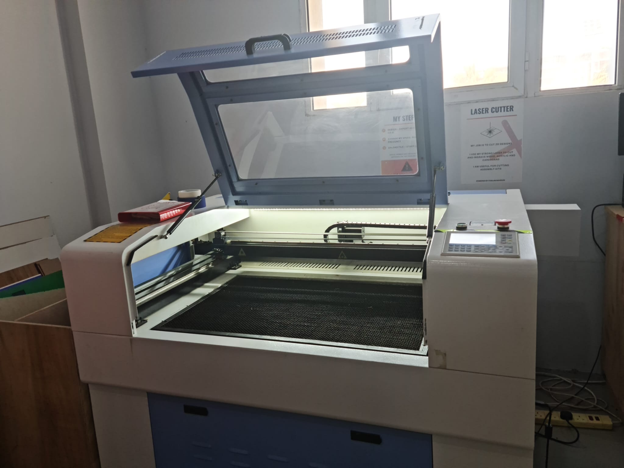
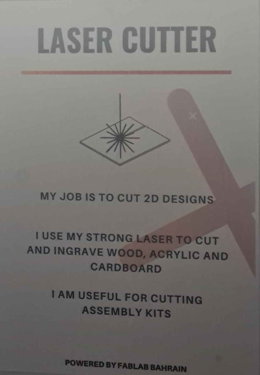
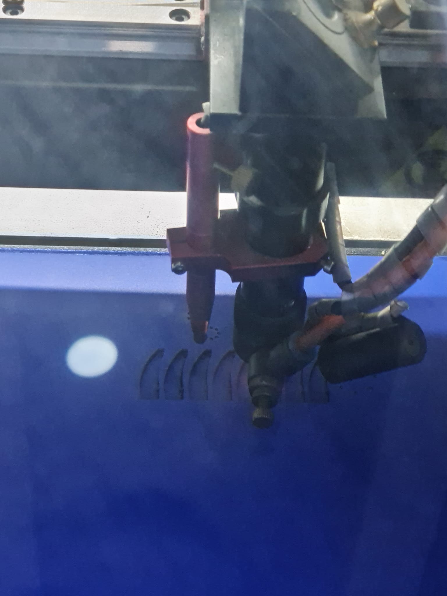
LASER Cutting
Laser cutting machine involves firing a laser, which thereby cuts the materials by melting, burning or vaporizing them. It can cut almost every material, from thin thickness boards to thicker ones.
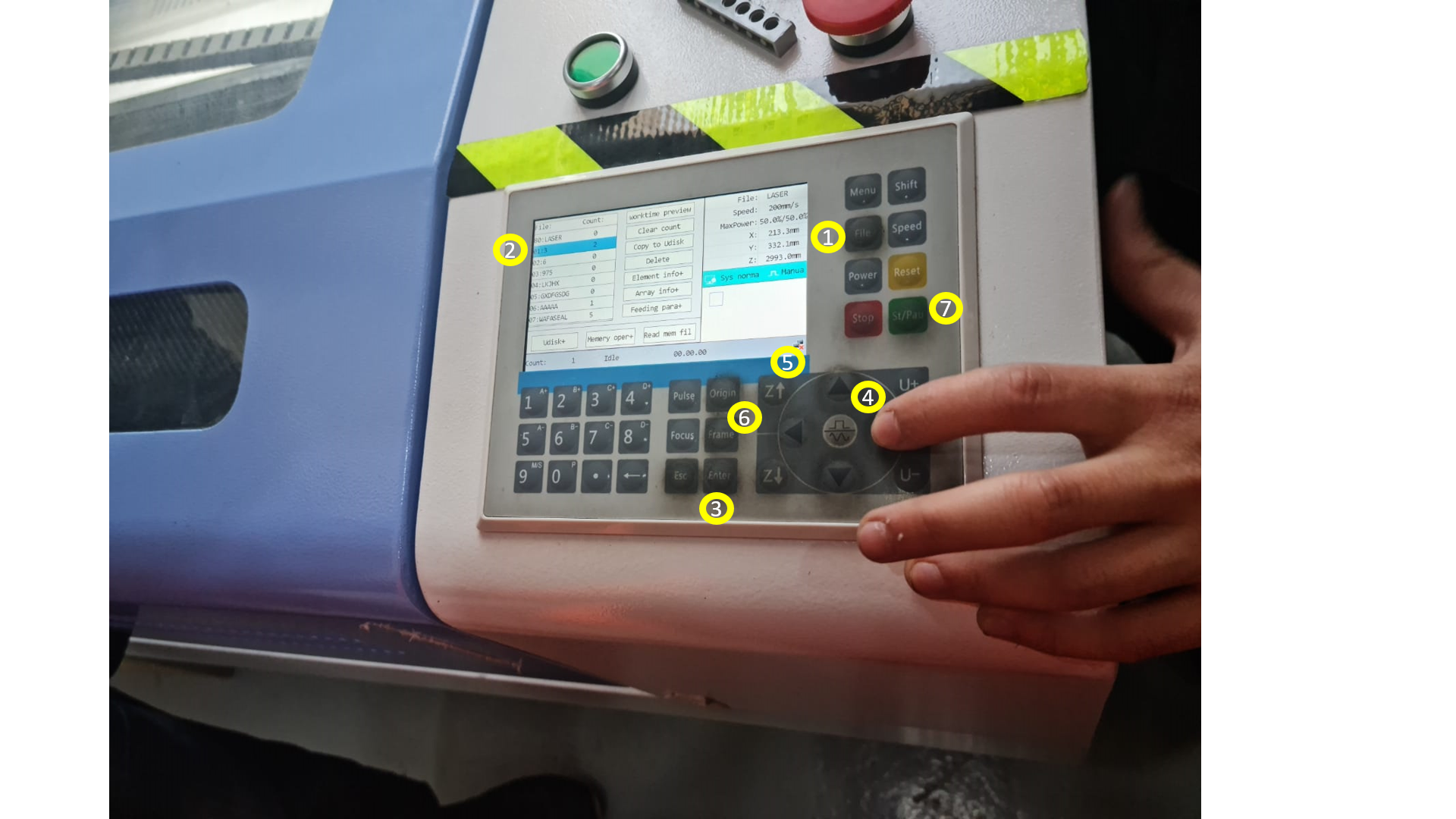
These are the steps that are taken, before starting the laser cutting process.
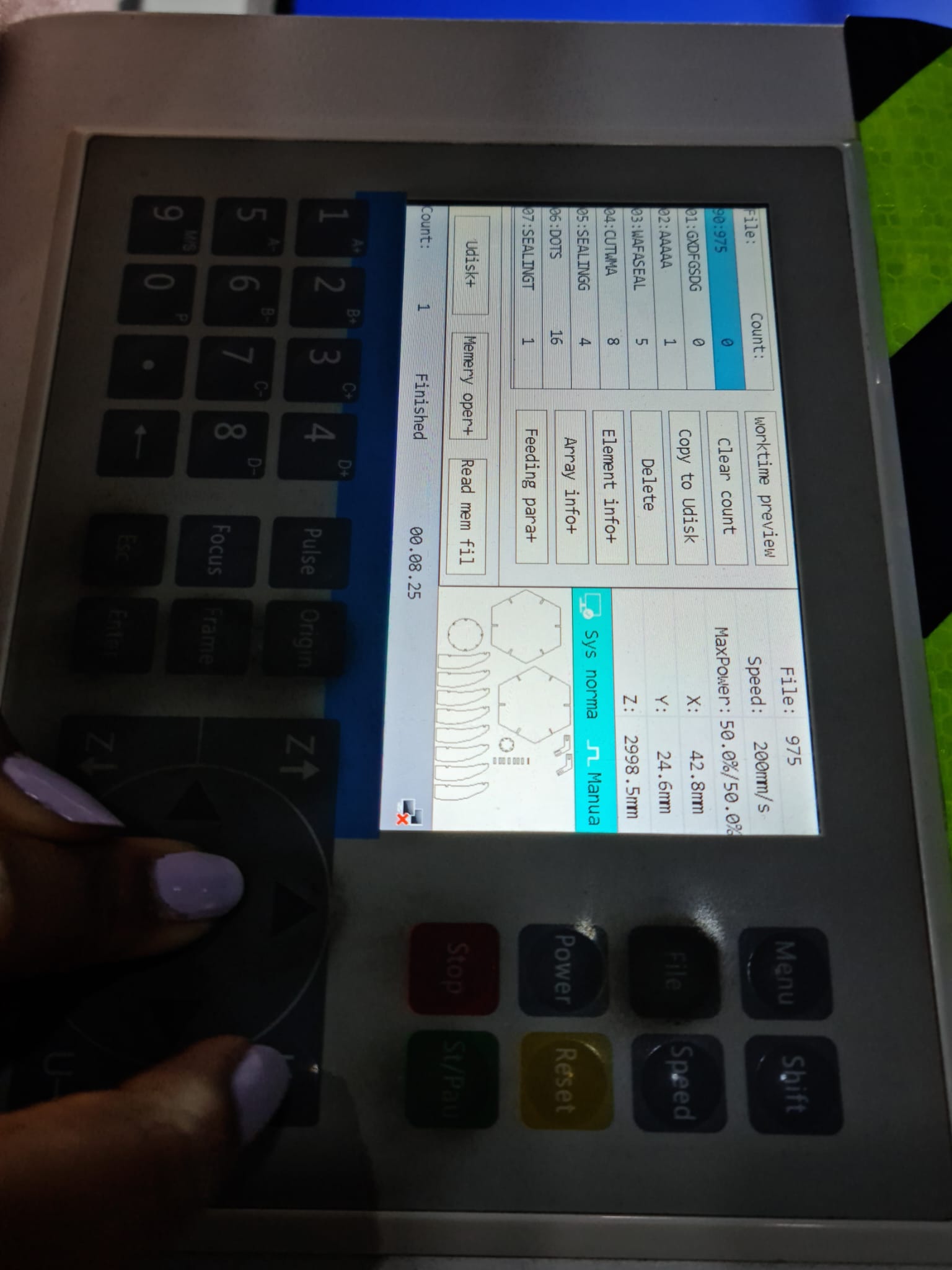
1- AXIS: In the machine, we have x,y & z-axis buttons, that helps us to select our starting point, before the laser starts cutting.
2- ORIGIN: This button allows the machine to start from a certain point, so it gives proper result, without the pointer going out of the frame.
3- FILES: We select the files, made in the PC and upload it to the machine, for it to laser cut the materials. And then, we press Enter.
4- FRAME: Frame is used for seeing whether the piece that has to be cut, fits or comes within the material or goes outside of it.
5- When we are sure, that all settings are correct, we move on to Press “Start” Button, to start the process.
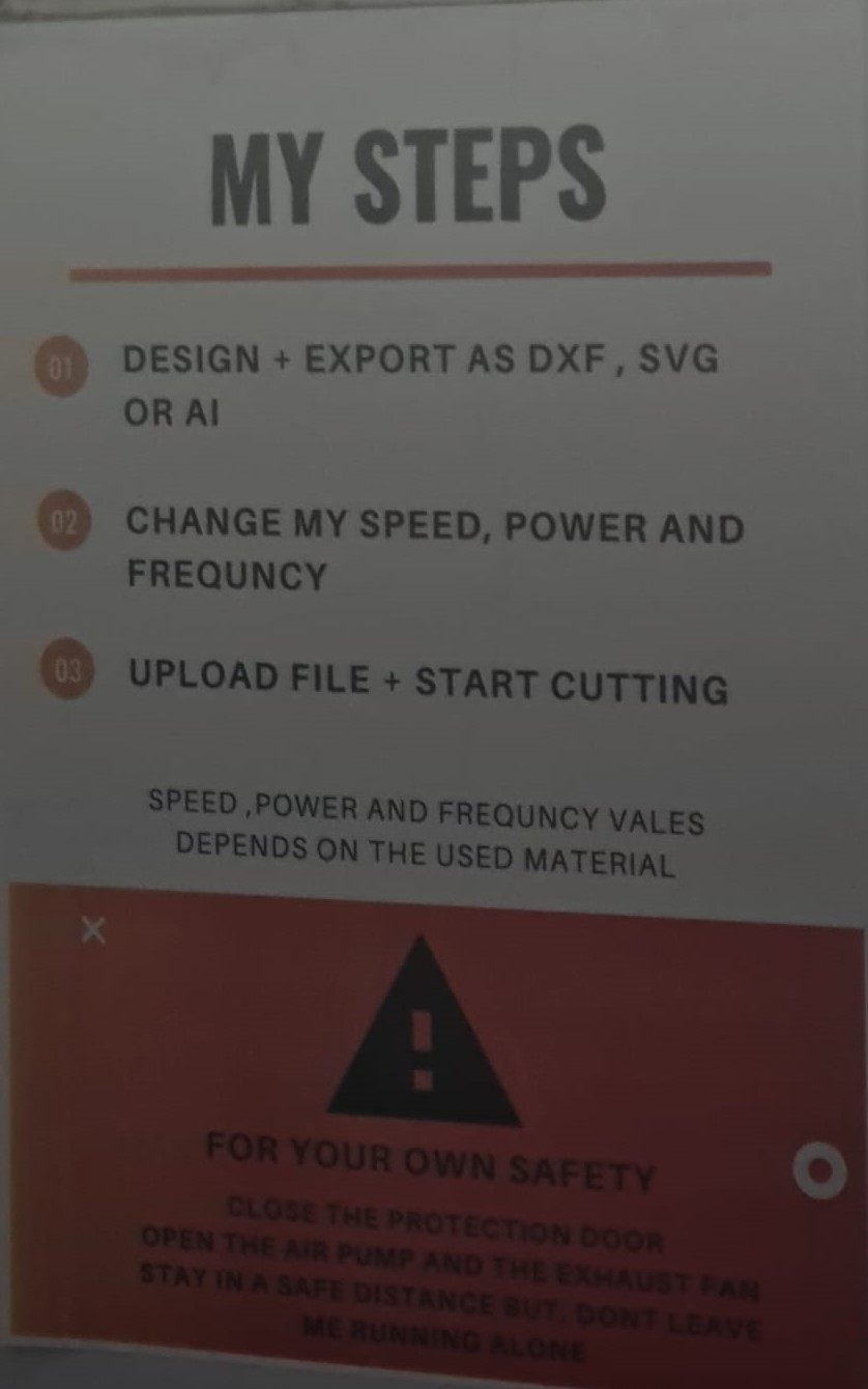
Also, these are some step guidance in terms of adding files to the machine etc.
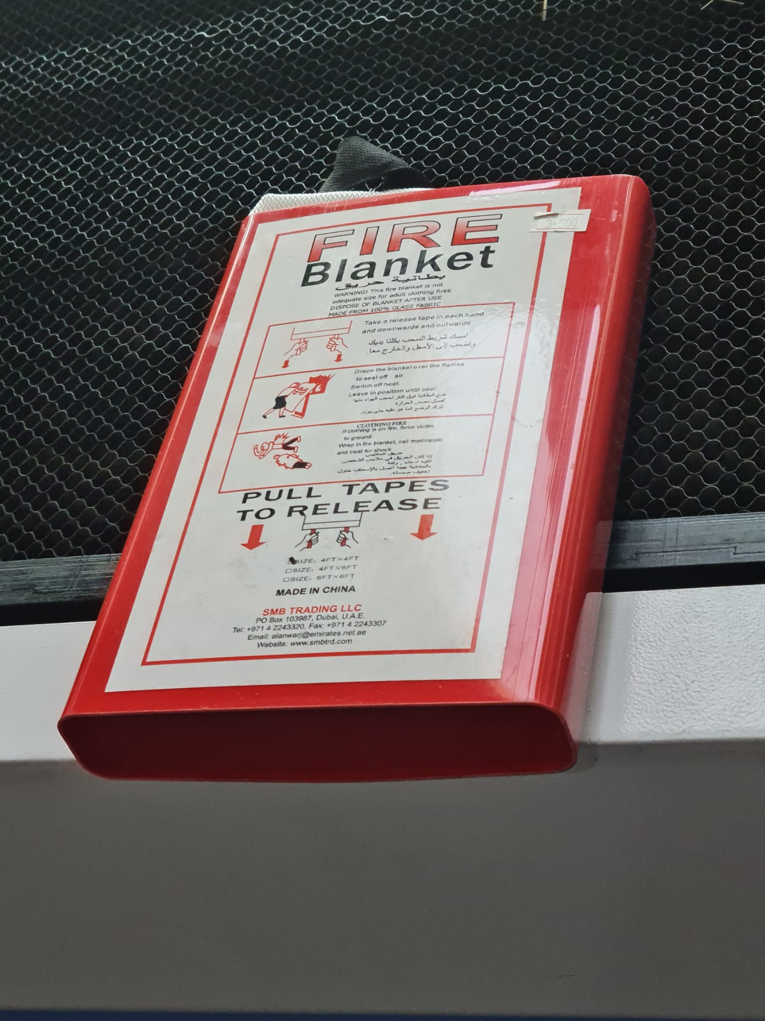
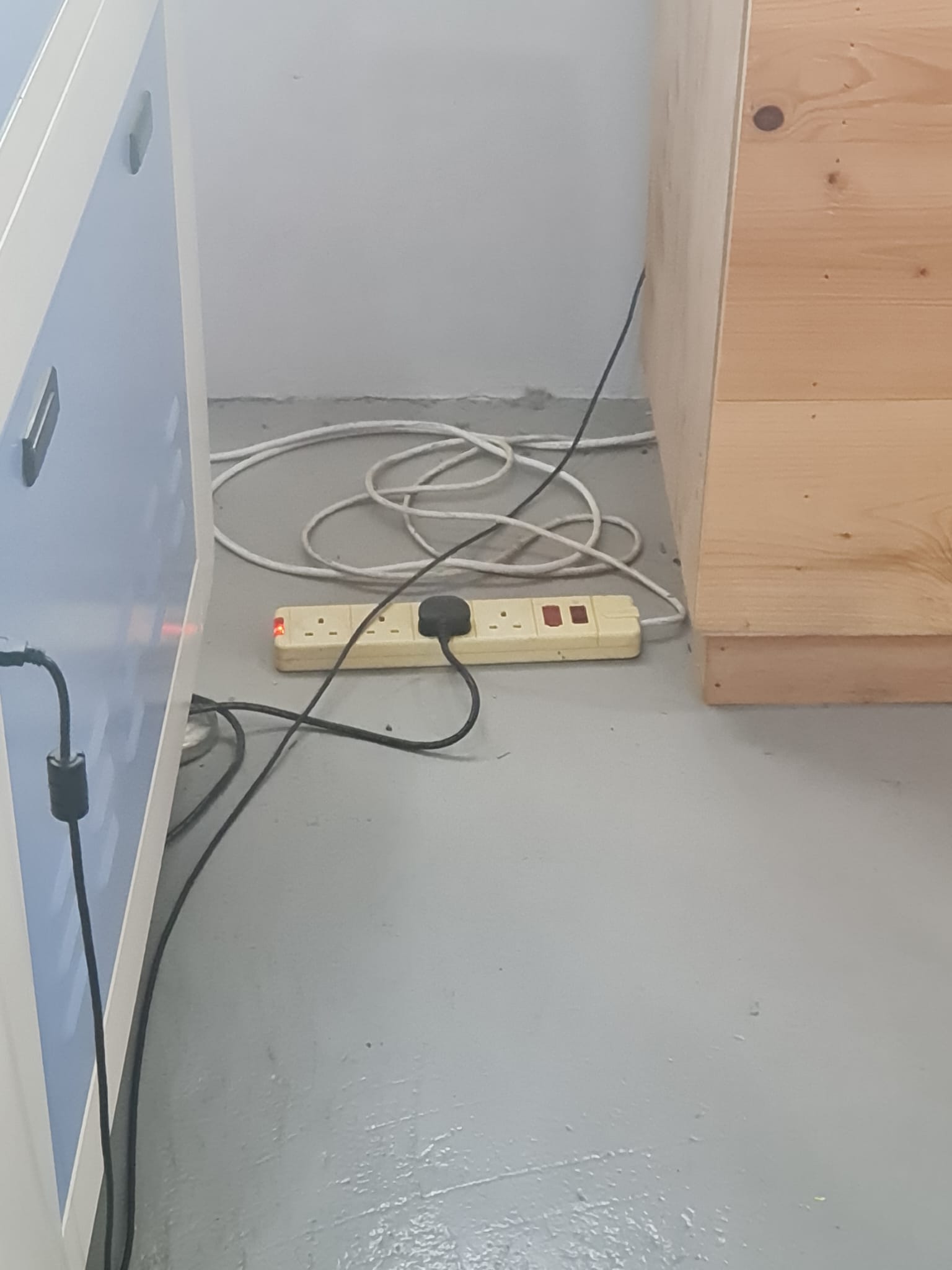
In case of Fire, a fire Blanket is used that is put inside the machine to extinguish the fire. In another case, the extension wire can also be cut off, to avoid spread of fire. And thirdly, Push the Red button, so the machine could stop working.
SAFETY RULES:
These include,
- When machine is working, always keep the door closed.
- Do not put hands on or near the machine, as the laser beam is very hot, and might cause burning of the hands.
Video of Axises (x,y,z)
KEY POINTS to note
1- The thicker the material is, the more power is needed.
2- If power is more, the speed should be less, in order to get better results. If speed is more, and power is less, the end result quality won’t be so great.
LET’S START EXPERIMENTING!
TESTING POWER & SPEED OF MACHINE!
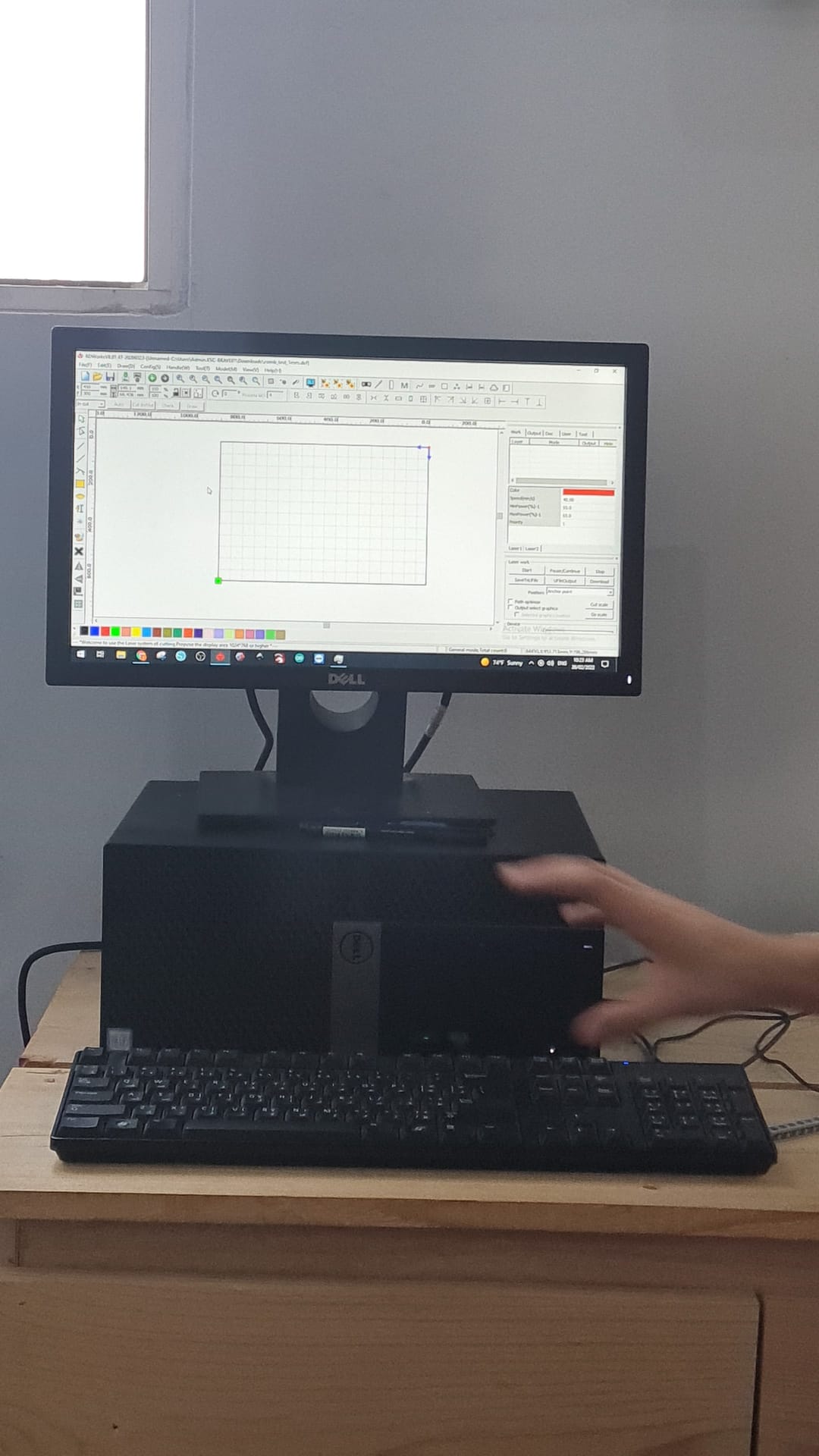
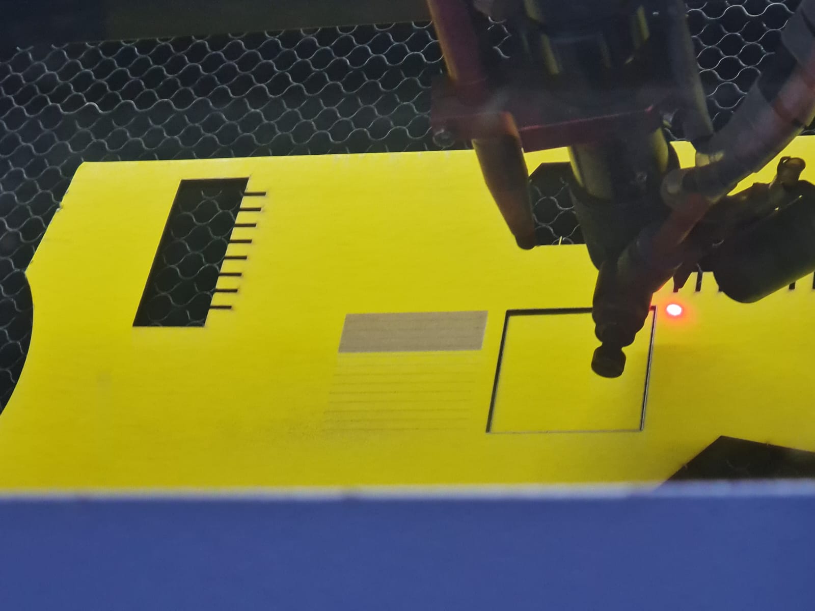
Our instructor started showing us the process of laser cutting.
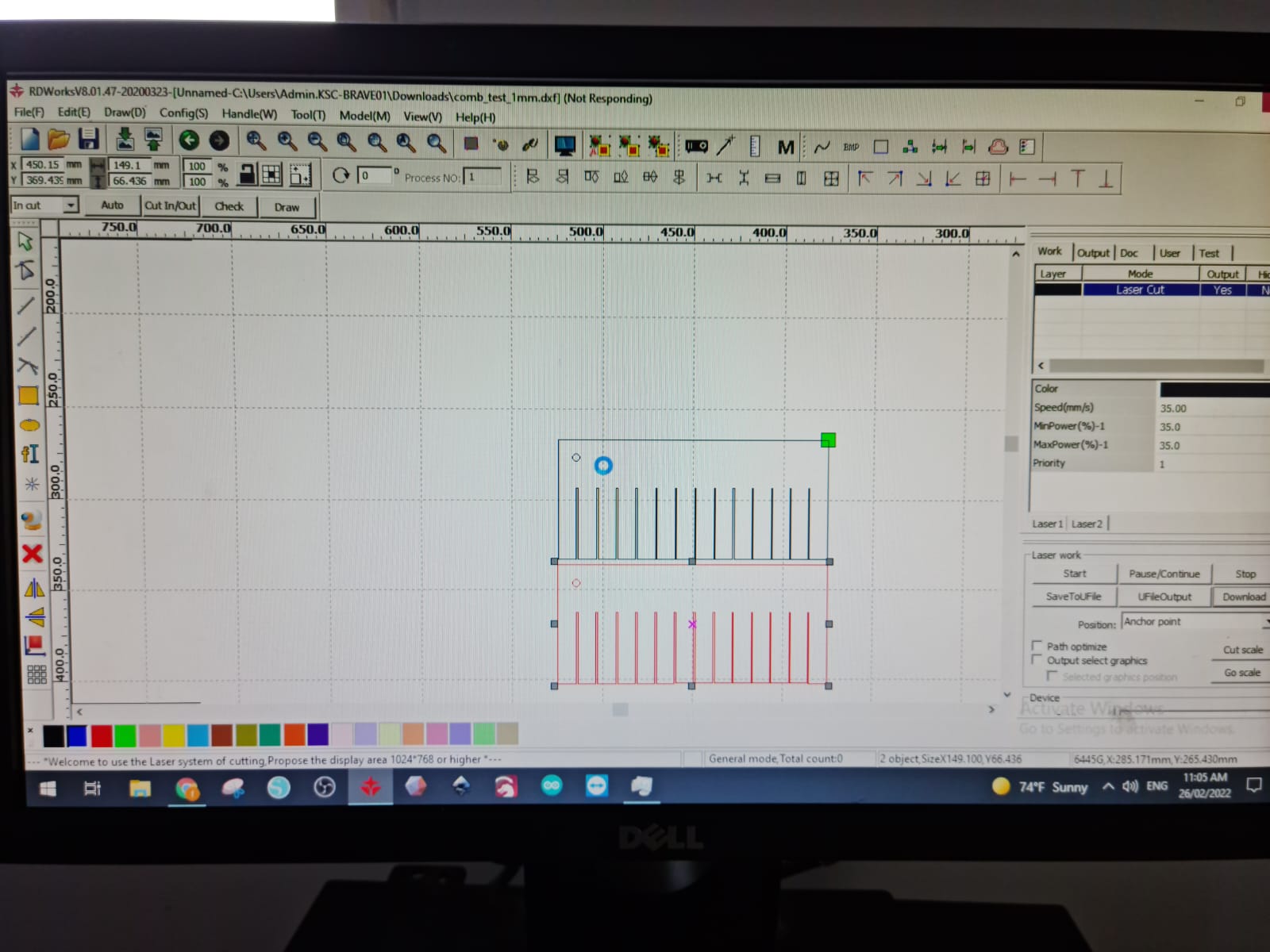
1- First, We opened the RDworks software, it being the software that is used to upload objects to the machine.
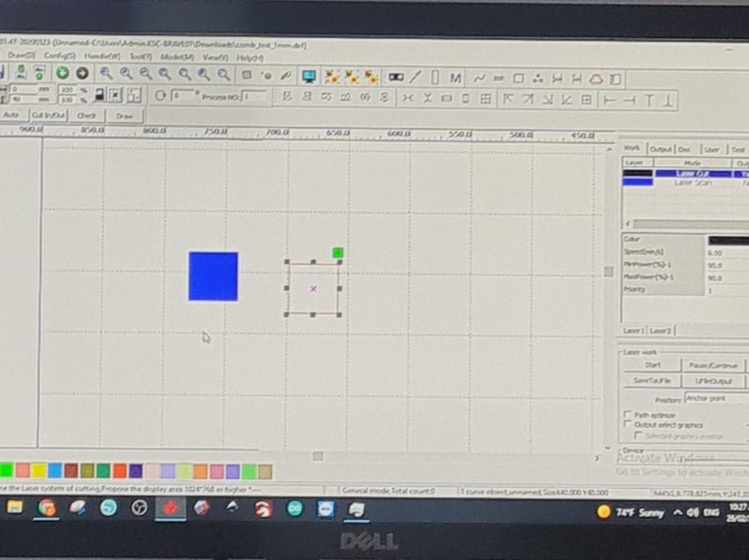
2- Then, We made 2 square boxes. One with Blue filled color, the other one without the filling. The filled color indicates Engraving. And also, we can change the colors in the setting, for all the different objects, which would indicate that each object will have different parameter settings to them. The green color point indicates the ORIGIN point.
3- Parameter Settings:
Speed: 20 mm/sec
Power: 90
4- We used small sheets, called Matboard! There is also a DIVIDER space, for keeping the Big, Medium and Small boards separate from each other. It also helps in keeping the area clean.
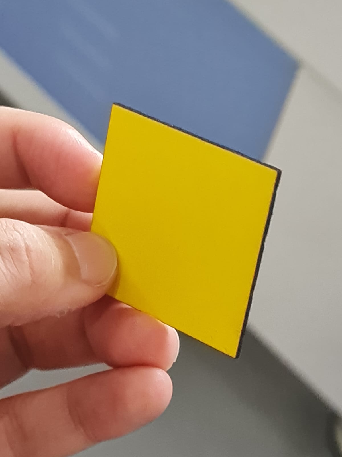
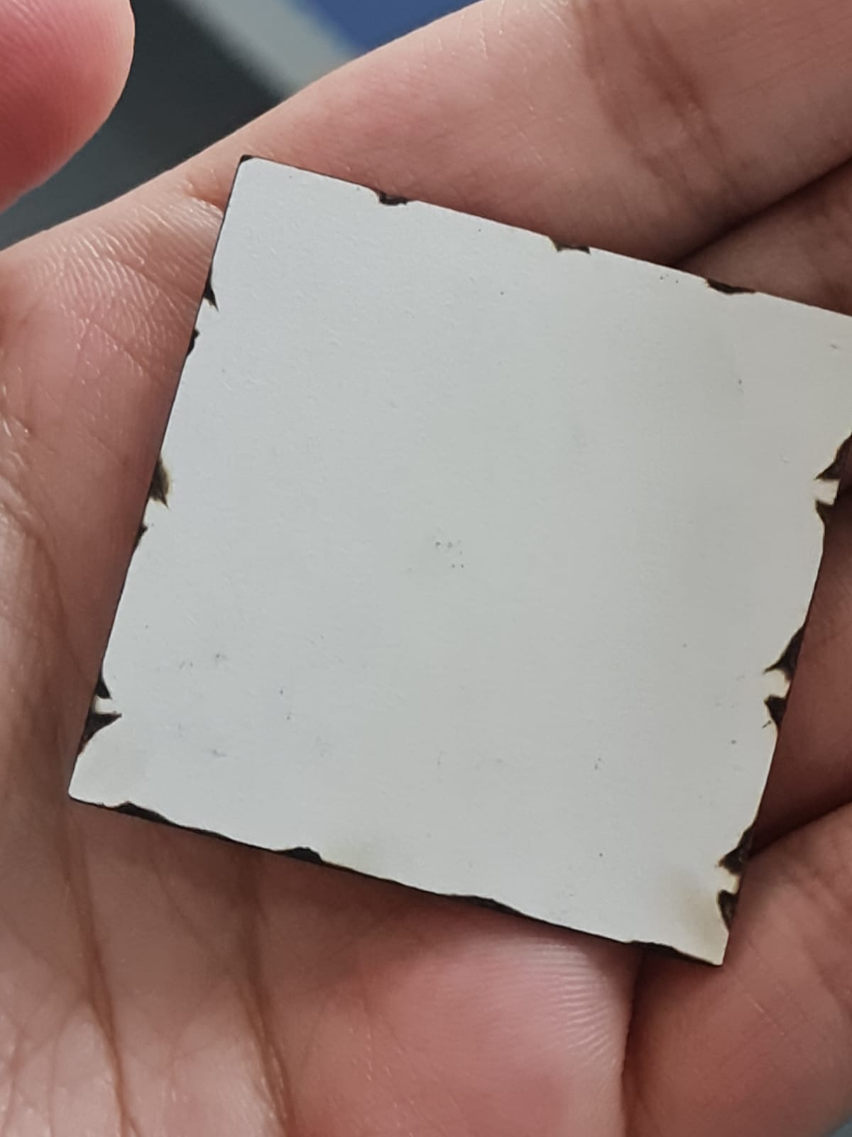
RESULT
5- We saw some burning on the sides of the square, which indicated that due to high power, the machine kind of changed the square’s dimensions, eating it up a little bit.
Video
6- Now, we changed the Parameter settings again. This time, they were:
Speed = 40 mm/s
Power = 20
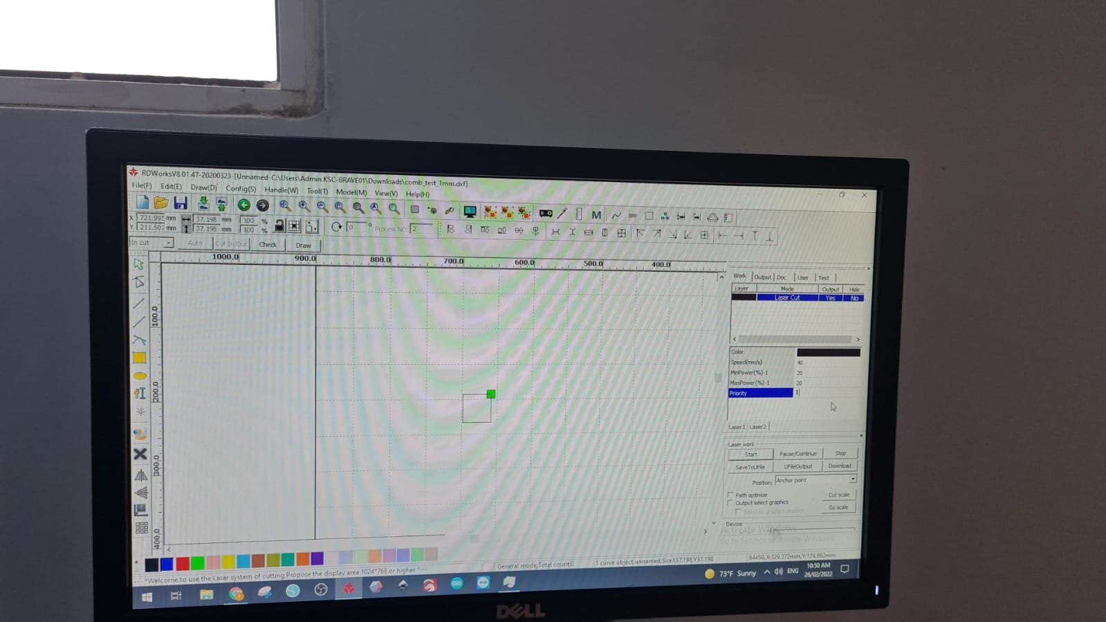
7- But it didn’t cut properly, because the speed was more, as compared to the power, which resulted in it, although, getting the work done faster, BUT the object was not cut properly, hence more time-consuming.
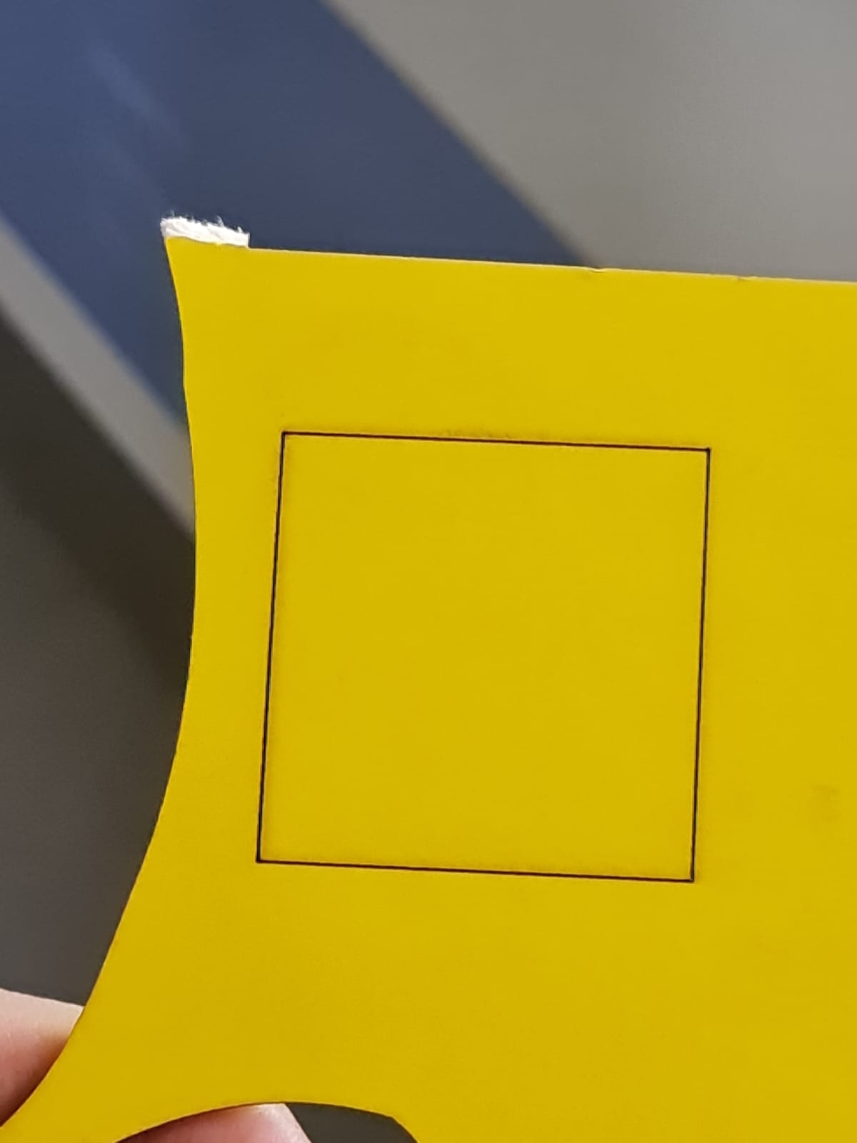
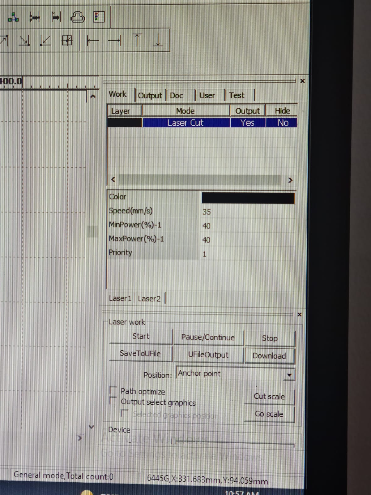
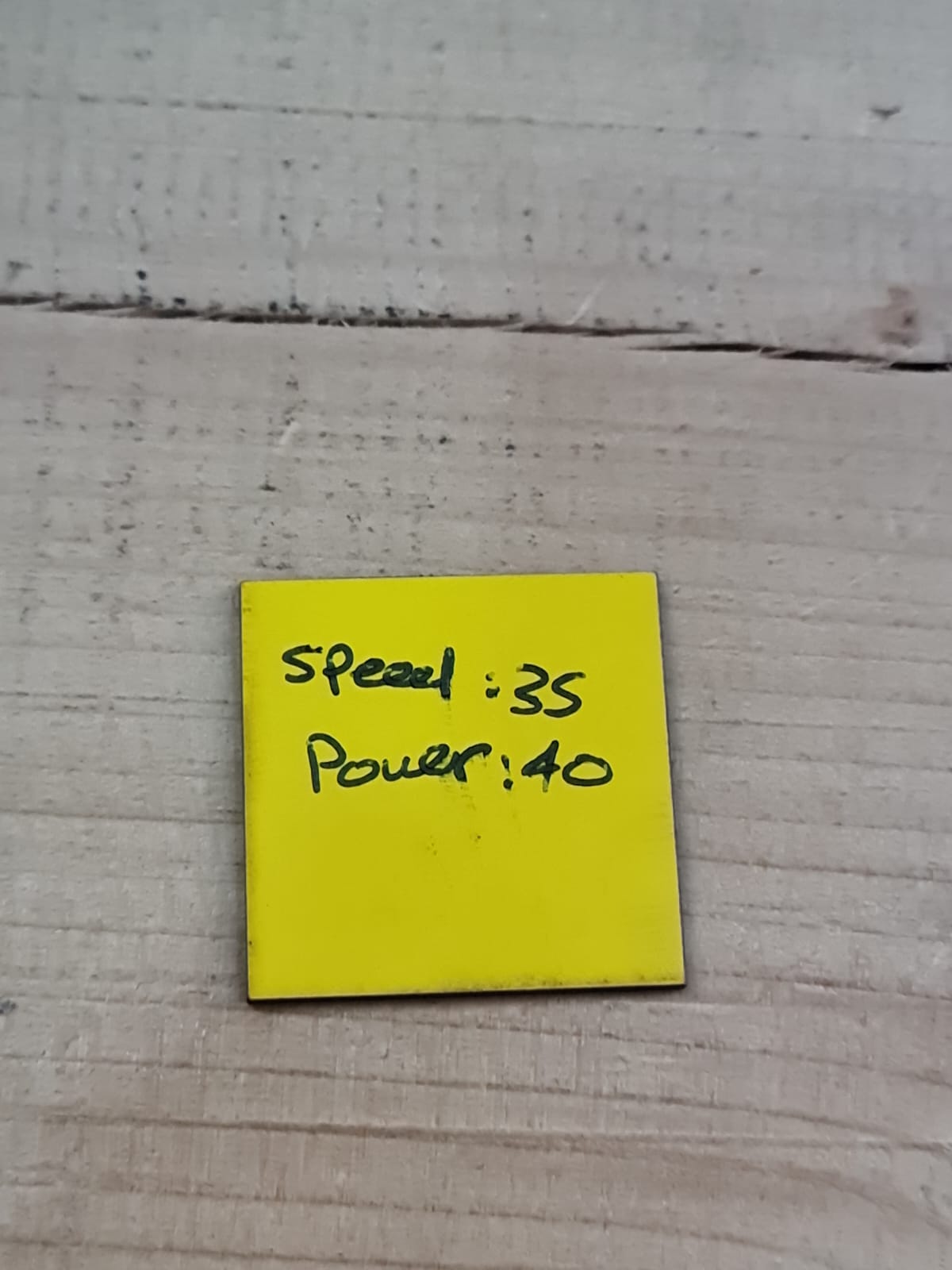
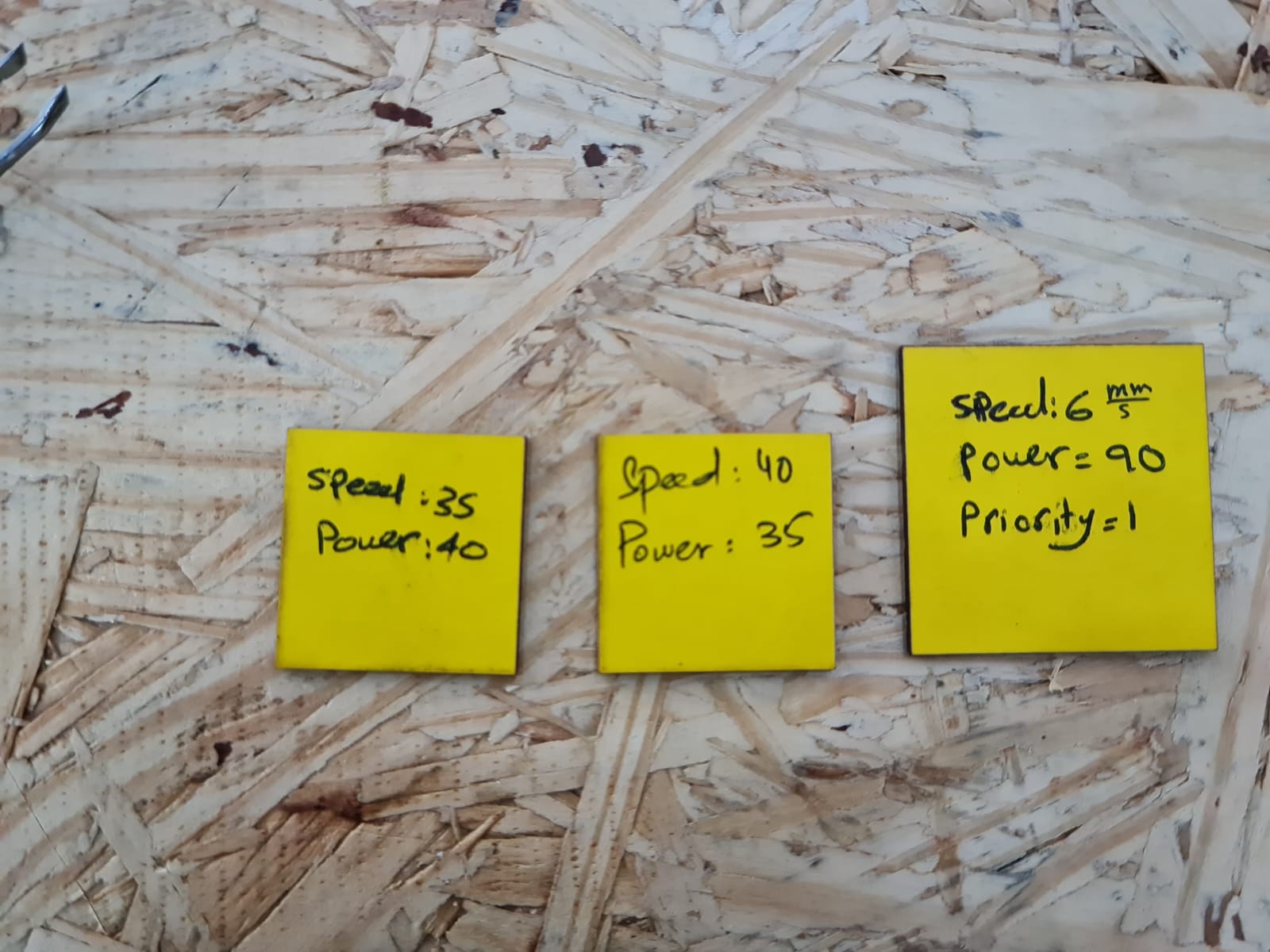
8- We started exploring more changes, by changing the Parameter settings again. Now, they were:
Speed = 35 mm/s
Power = 40
Video - Cutting Part
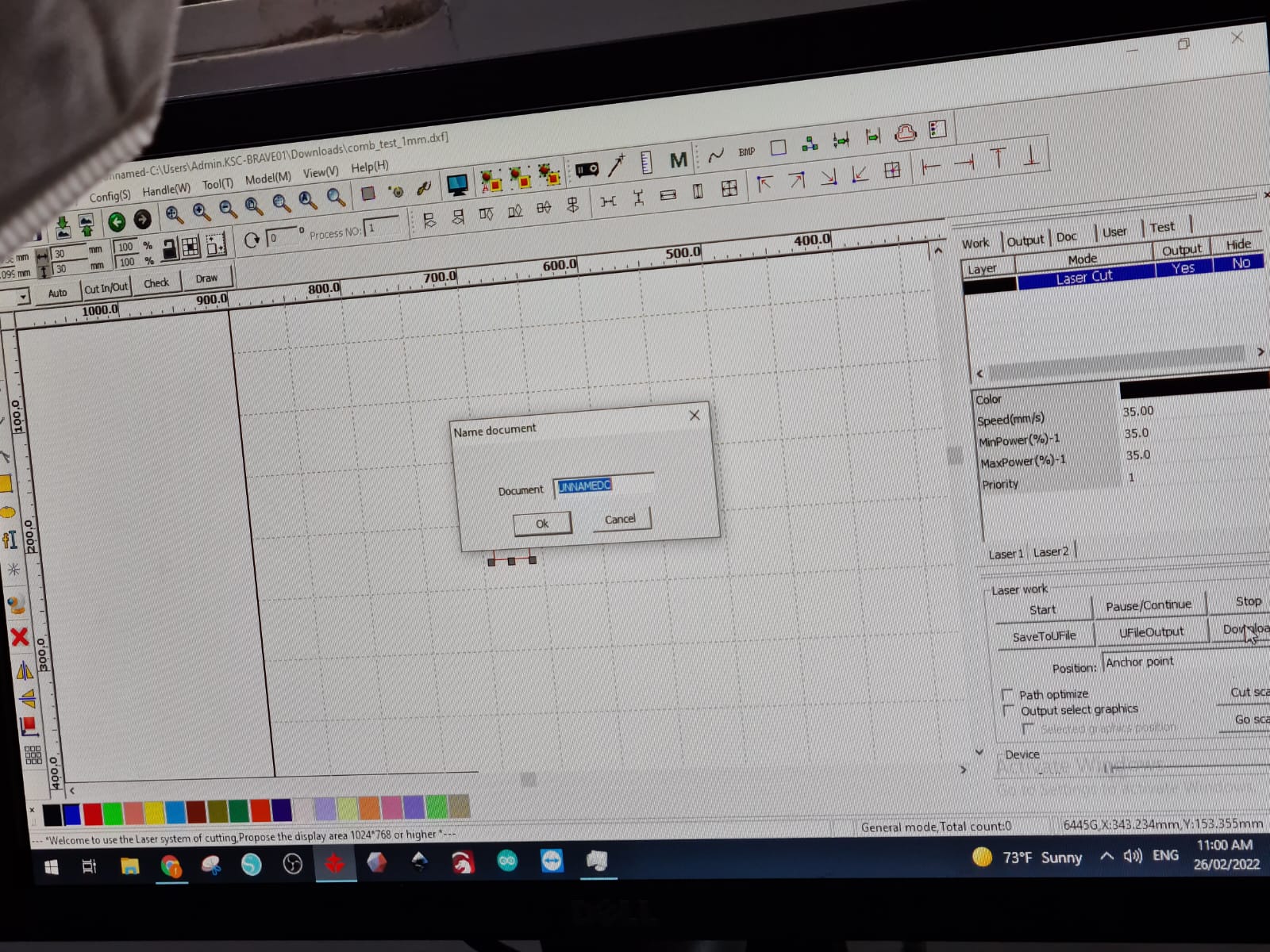
9- Then, we gave them all the same properties, that is:
Speed: 35 mm/sec
Power: 35
Video
The result was good.
Overall Comparison
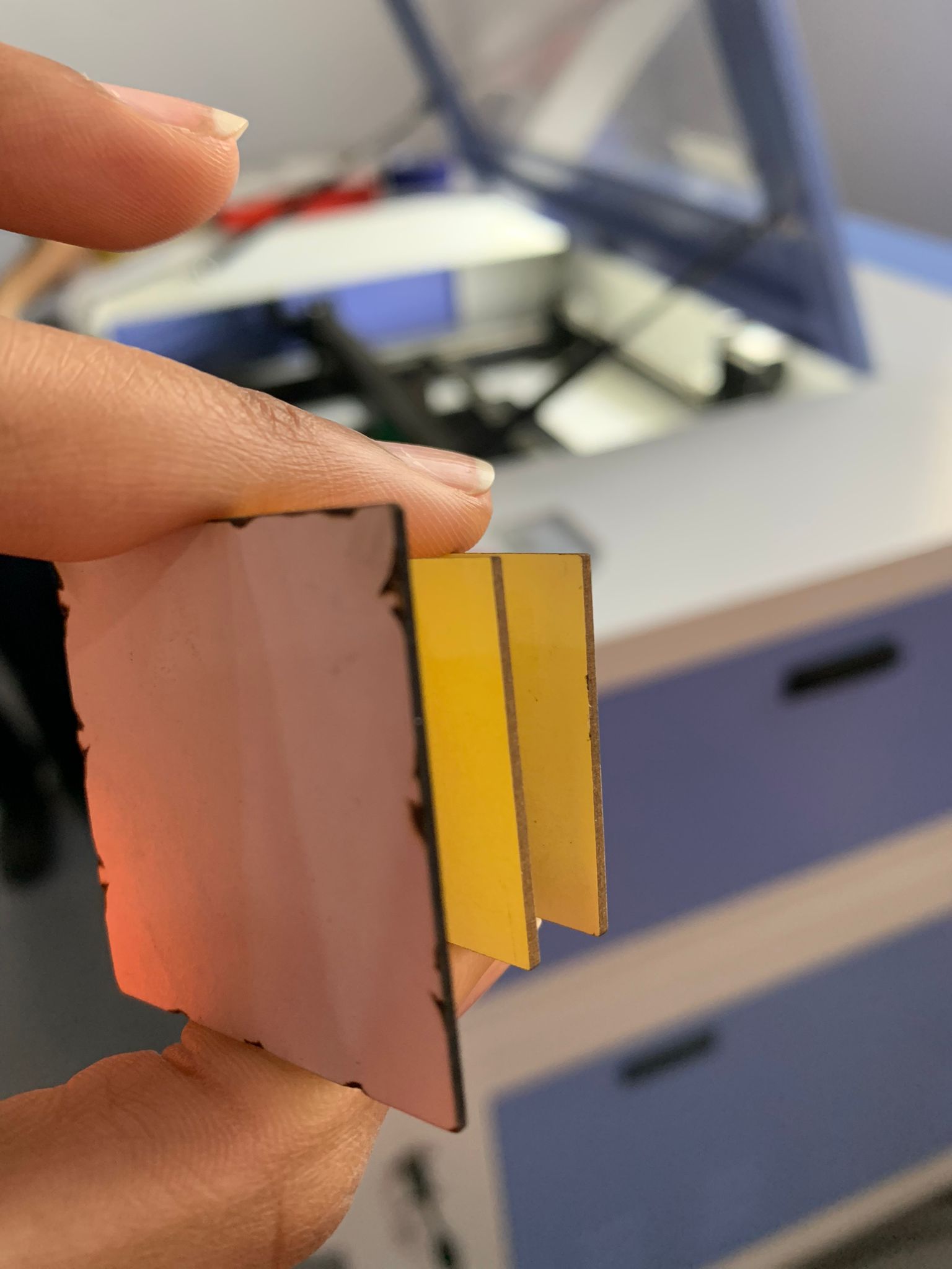
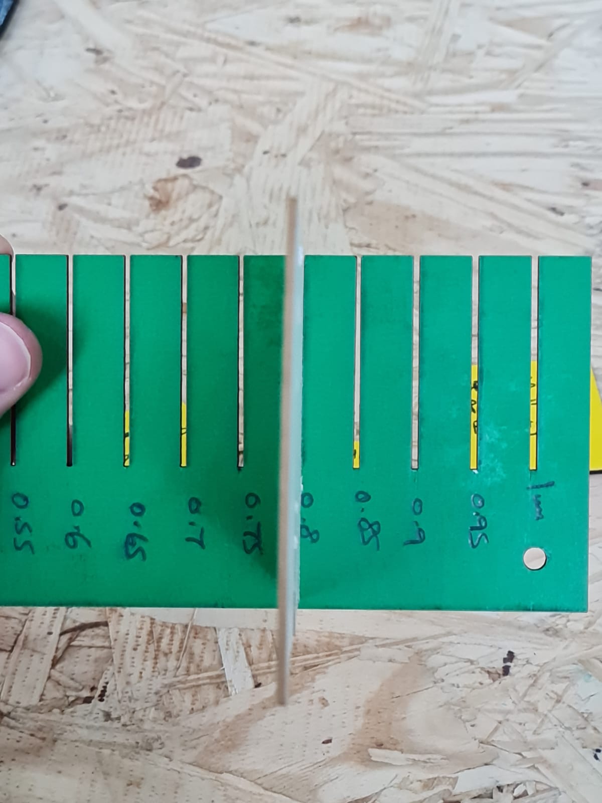
FITTING TEST!
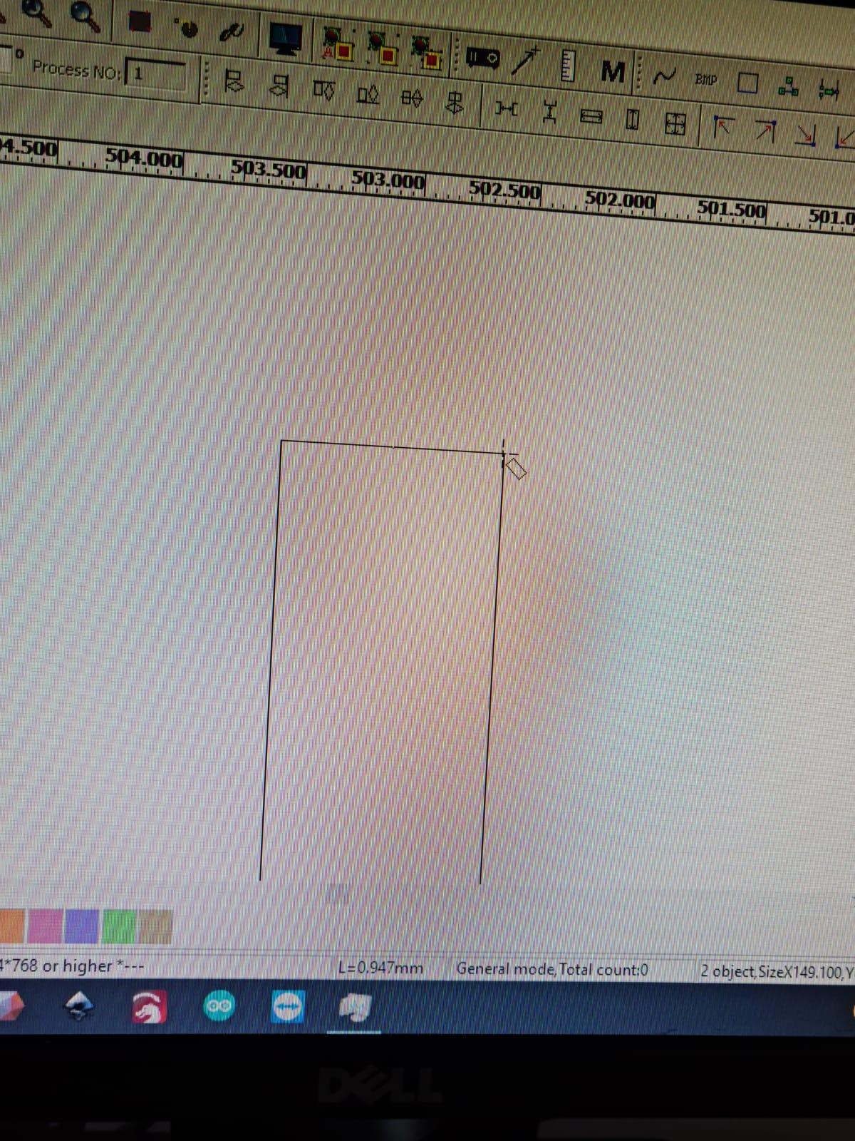
It is always recommended, to test the fittings first, before moving forward with the cutting process.
Taking this example into consideration, this is almost a 1mm gap distance between the 2 lines.
Video
KEY POINT to note
In order for the materials to stay fixed with each other, the fixing numbers should always be the same.
Videos explaining the fitting process
Here are detailed videos of our instructor, showing and explaining to us, how to use the fitting boards, and what to expect if we use same numbers or different ones.
Our Selection
Our group tried selecting a number, that would let the materials stay fixed, i.e. for it to be not too tight, and not too loose either.
We settled with 0.8 meter gap, as it gave a good balance to the material boards.
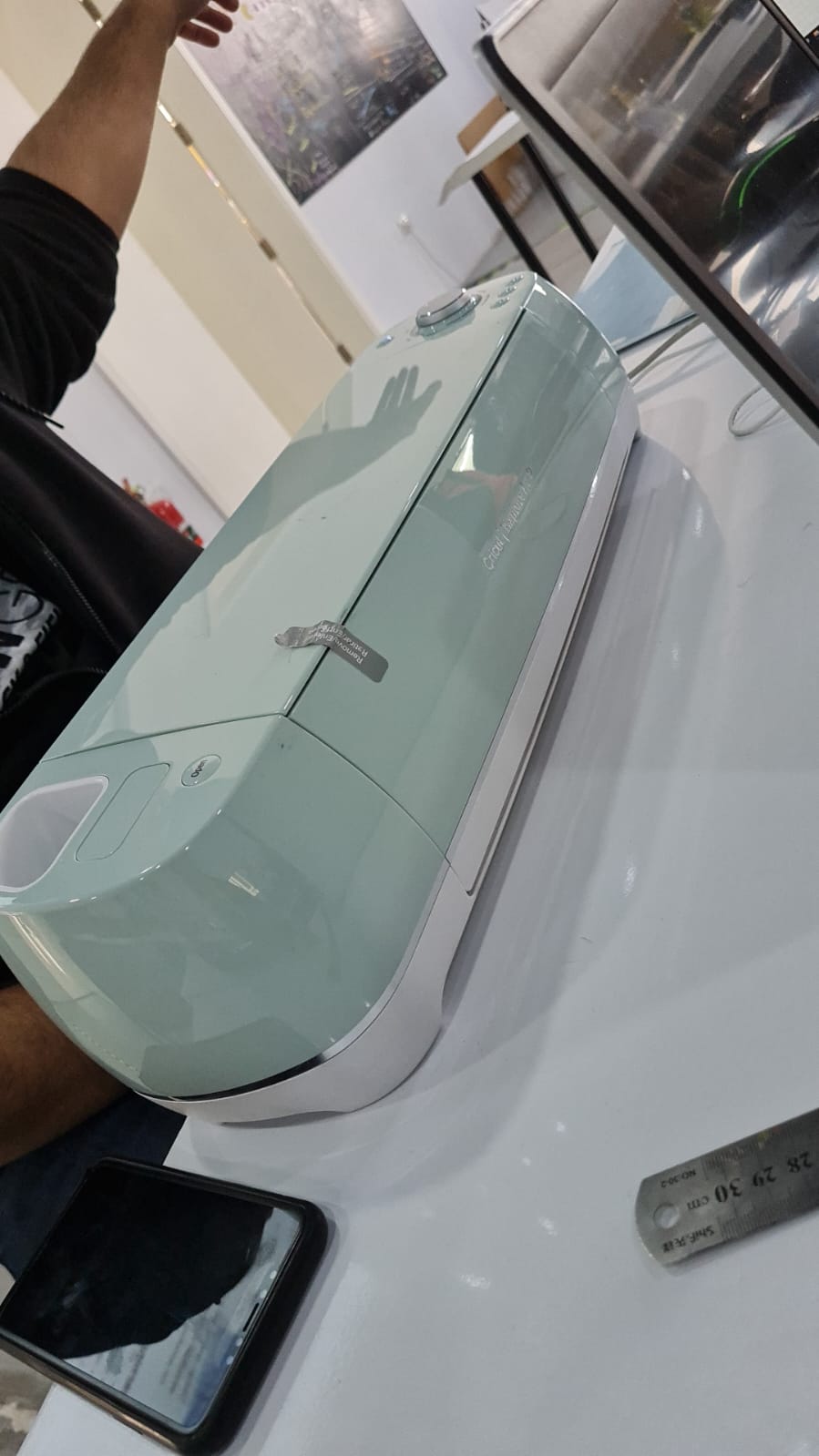
VINYL Cutting (INDIVIDUAL ASSIGNMENT- PART 1)
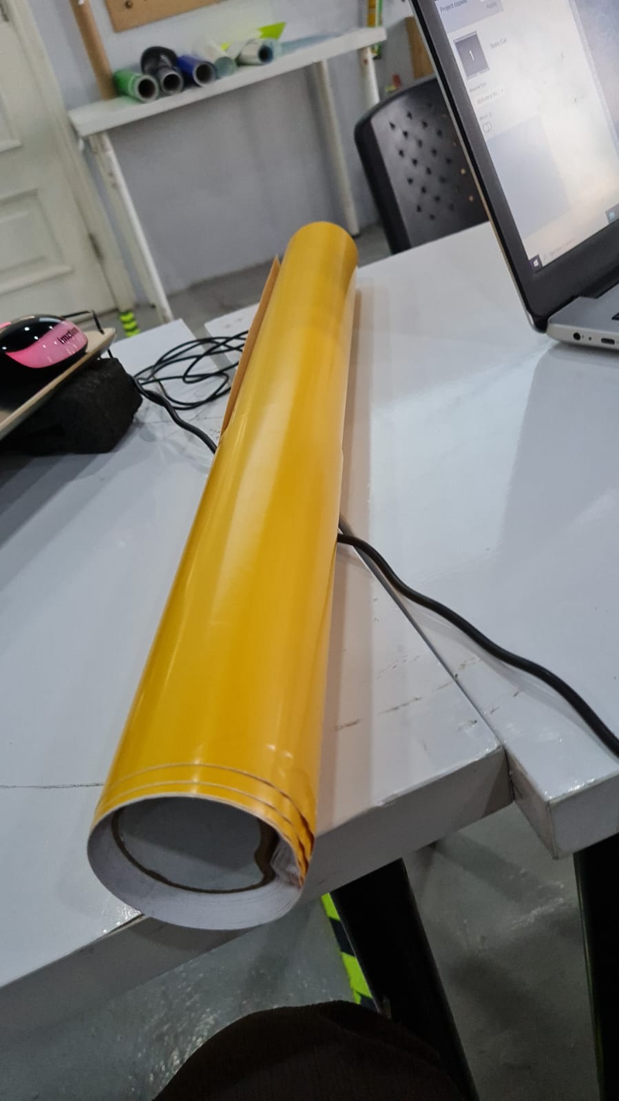
Vinyl cutting is the process of cutting vinyl to create custom designs. Vinyl can be cut in different shapes and sizes, then applied to cars, windows, electronics cases, or just about anything else!
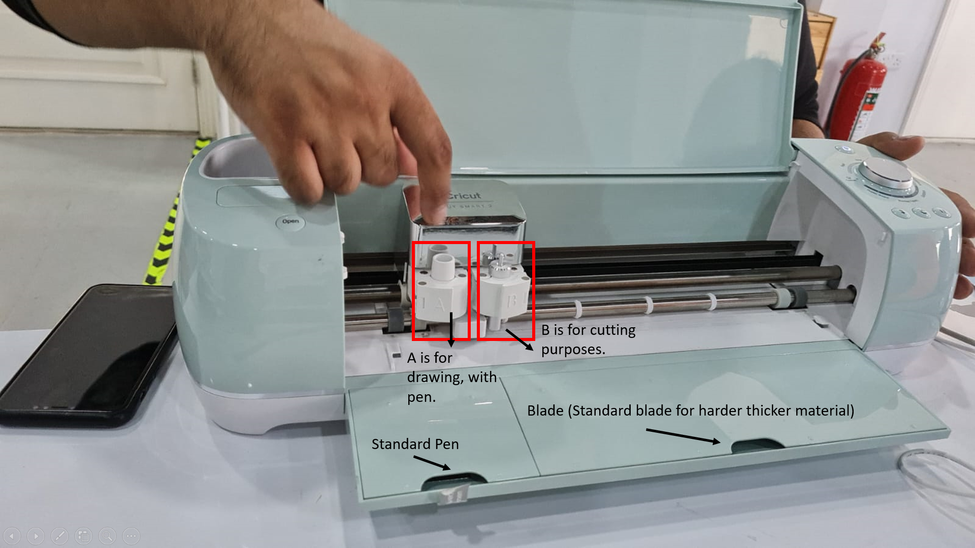
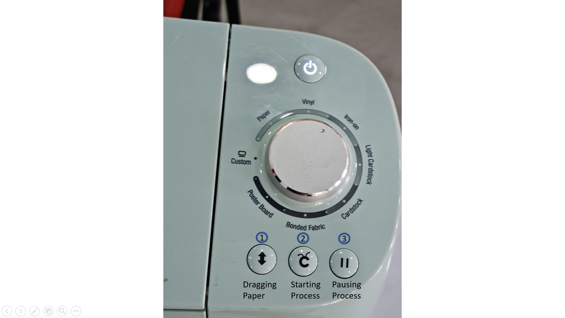
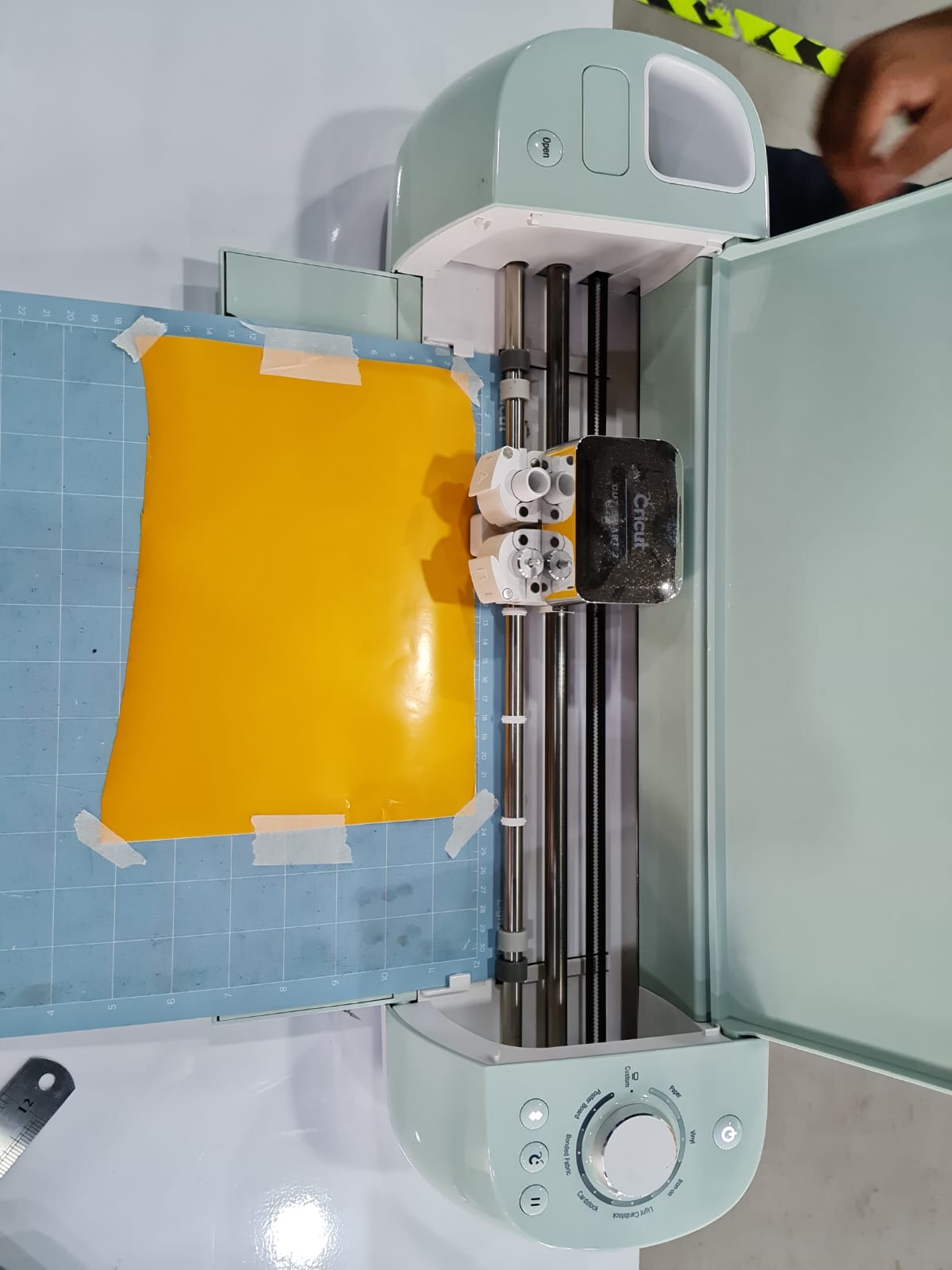
There is a motor section that goes in x axis, and roller tyres that drag the paper up. There are 2 sections inside. One is called “A”, and the other “B”. “A” is used for drawing with pen, for example. While “B” is used for cutting the paper or vinyl into desired objects, for example. There are separate pens and blades in the lower eclosed sections.
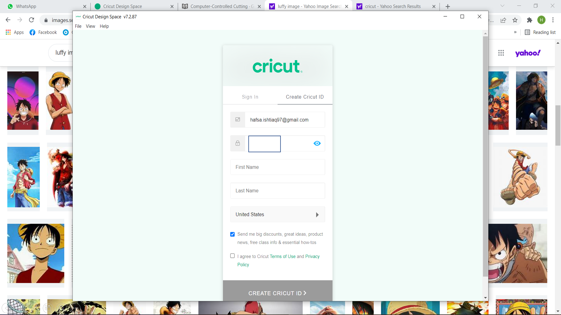
Now, in order for the machine to start working, we have to download one software for it, called “Cricut”.
CRICUT
Click here to download CRICUT software
Cricut is a design software, that is used for editing pictures, making holes or voids, and then seeing the images by clicking on preview, to see how the final image result would look like.
The steps are as follows:
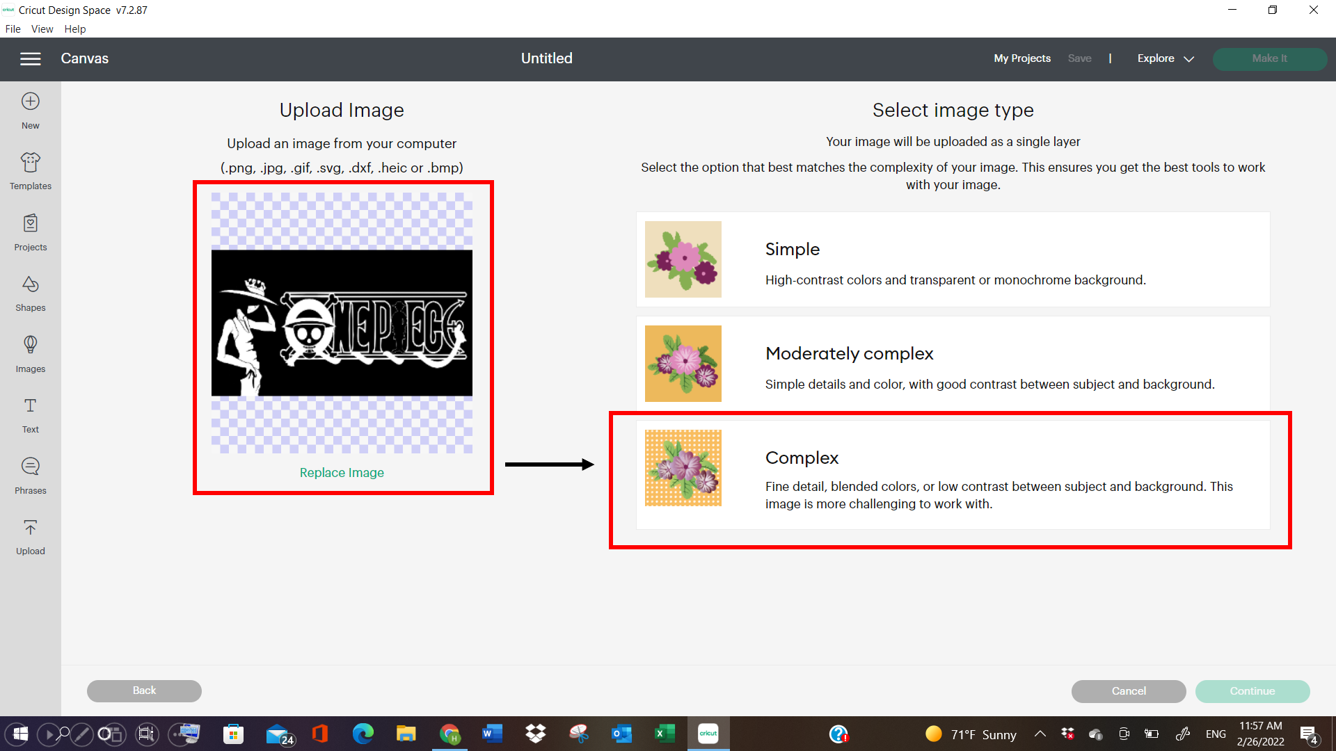
1- I went to google, to search for a picture. And, I chose this logo of an anime, called “ONE PIECE”. Click here to see different ONE PIECE anime LOGOs. After downloading it, I saved it on my desktop folder, and started proceeding with the process.
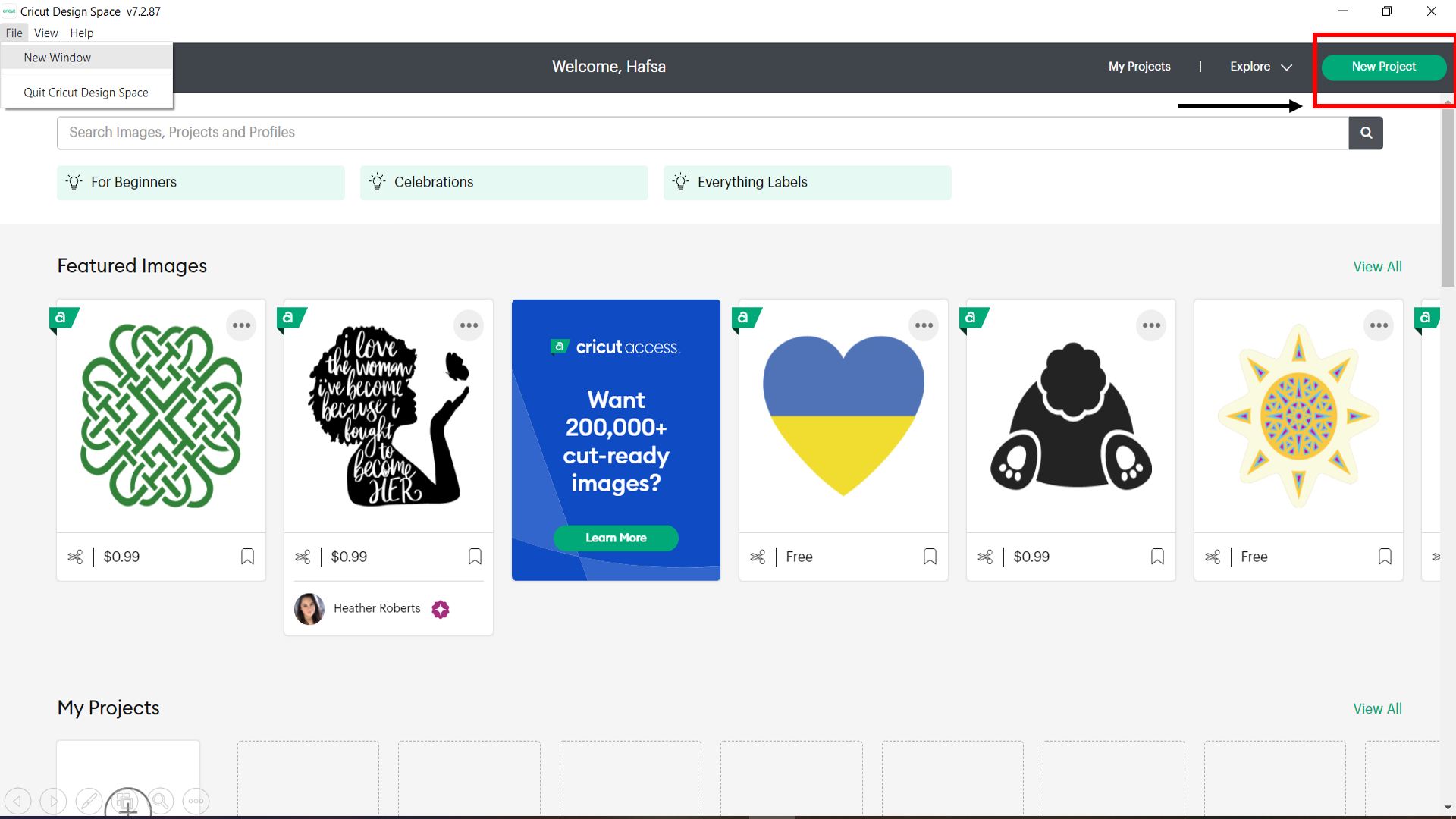
2- I downloaded CRICUT software, and we were asked to create an account for ourselves.
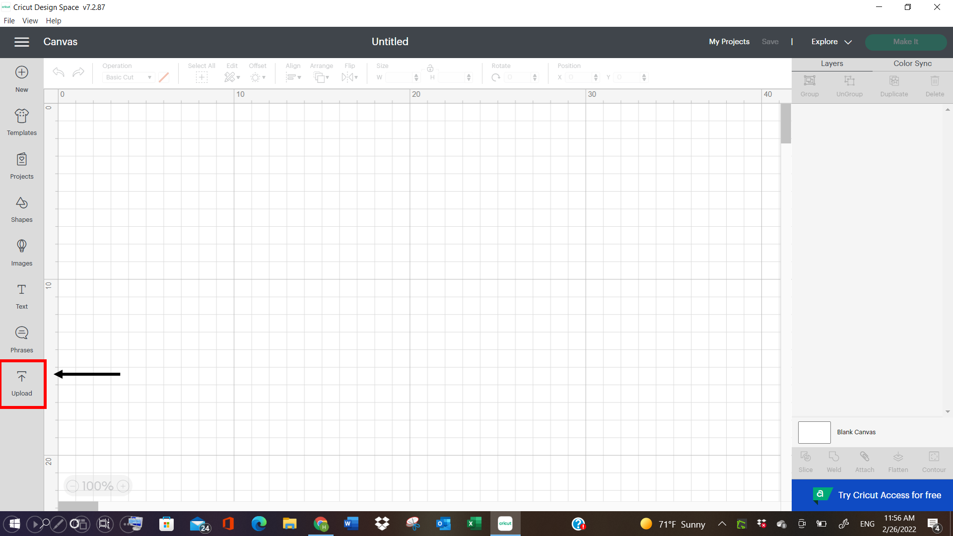
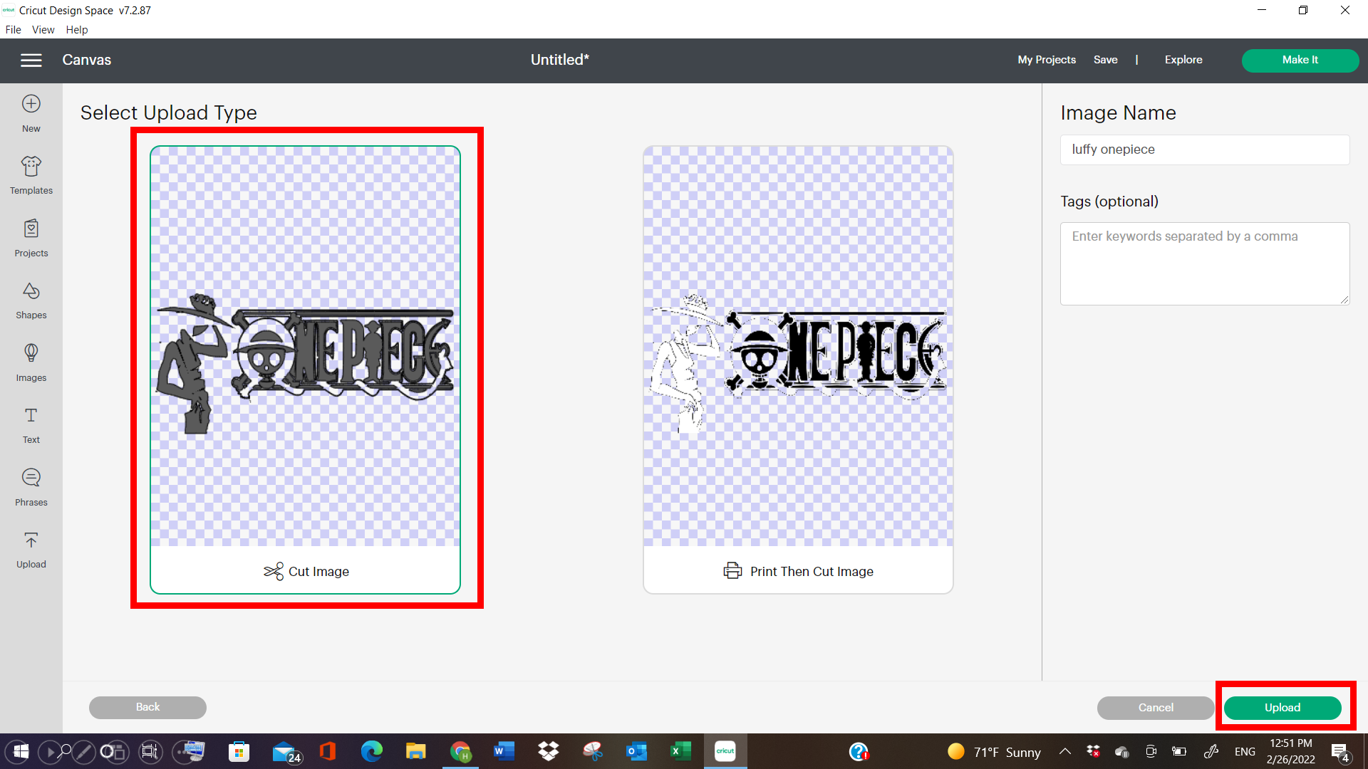
3- Then I opened new window project, and Clicked on upload.
4- I uploaded the image from the Desktop folder, and select “Complex” detailing in it. As the name suggest, “Complex” means more detailing in the images selected or uploaded.
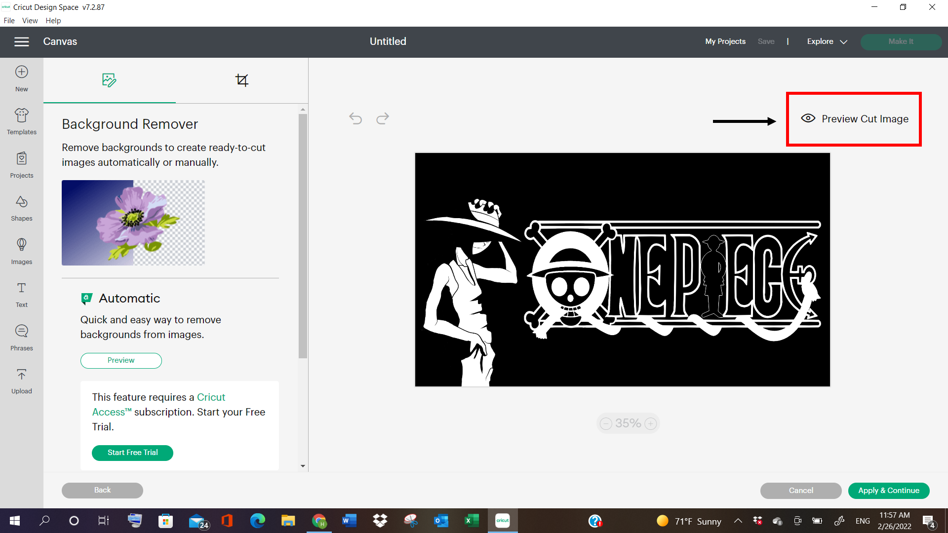
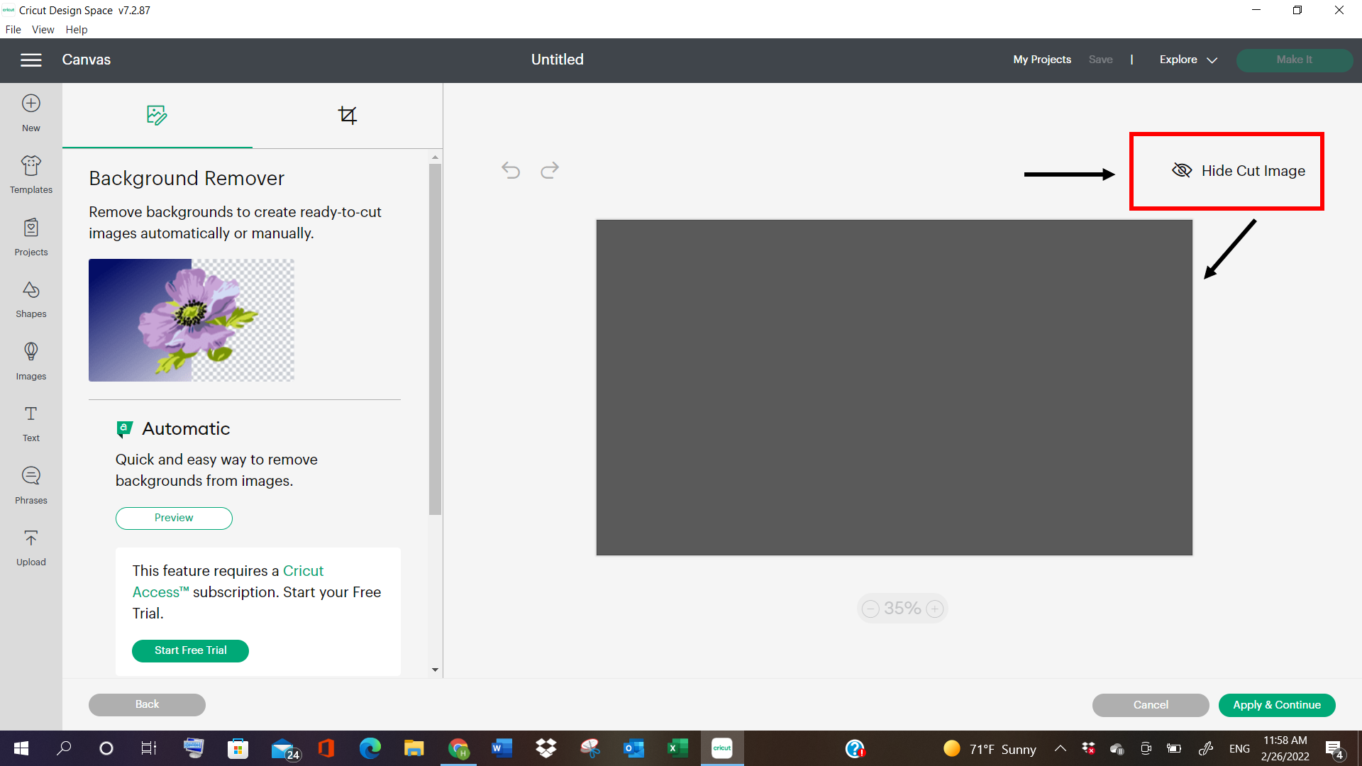
5- After clicking on Complex detailing, I went to see the properties of the images, by clicking on “Preview images” and “Cut images”. The cut image showed nothing but grey color, indicating that the image wasn’t cut anywhere else, so I went to “Manual” options and clicked on “Select”.
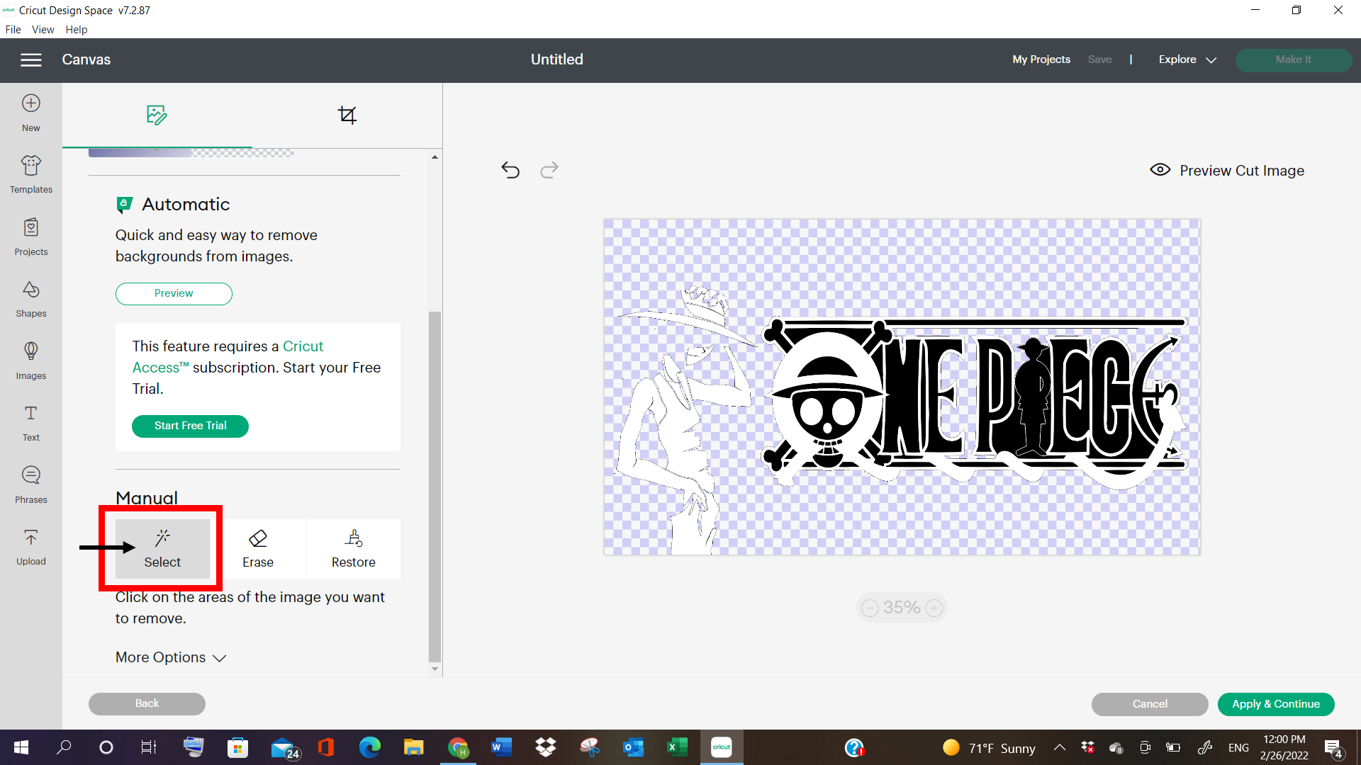
6- “Select” option allows us to select the areas that need holes in the image, allowing us to see the outer lining of the final product.
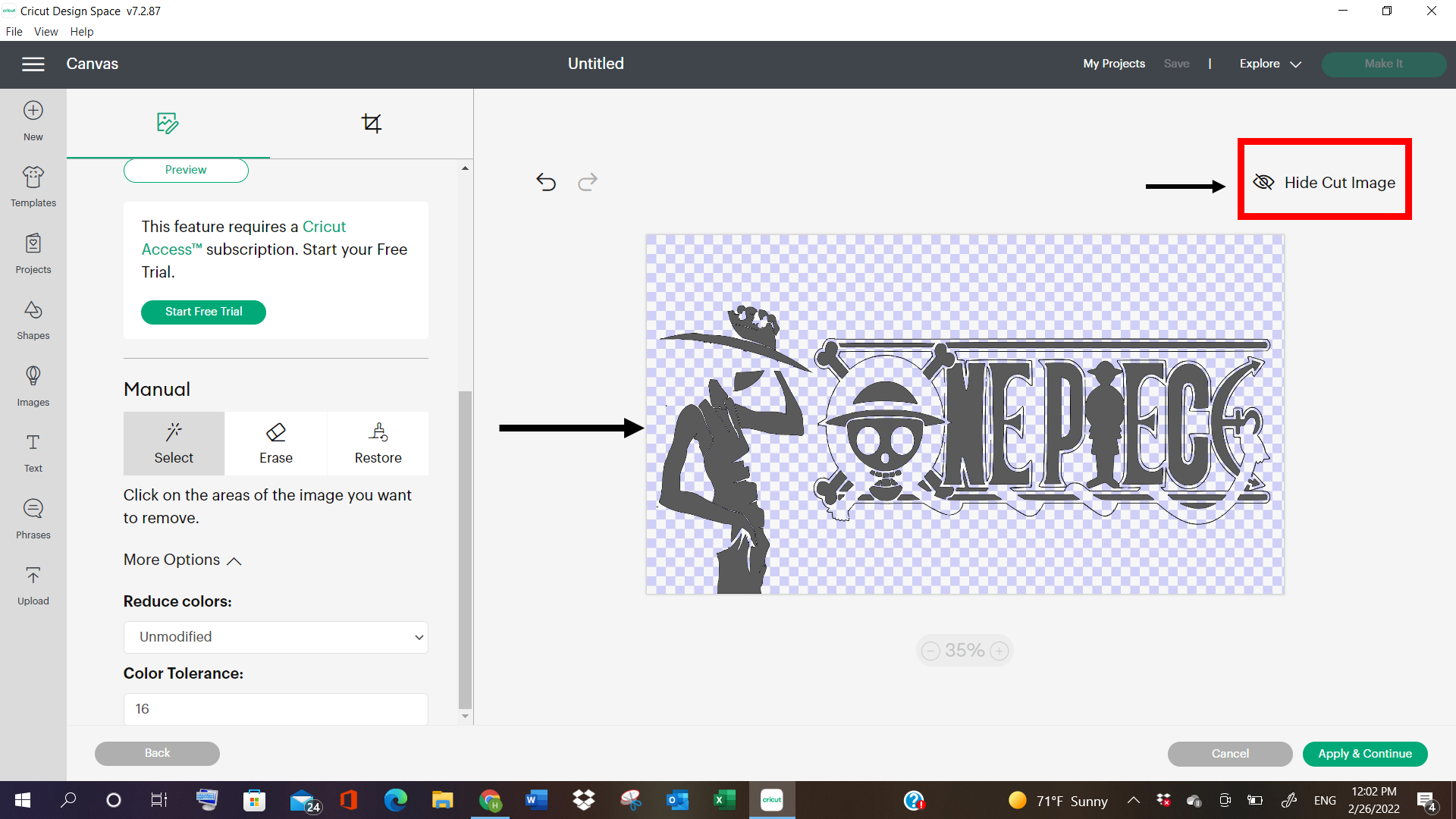
7- After selecting the needed areas, I went to preview the image, and got the final result. Then i proceeded further with the “Apply and Continue”.
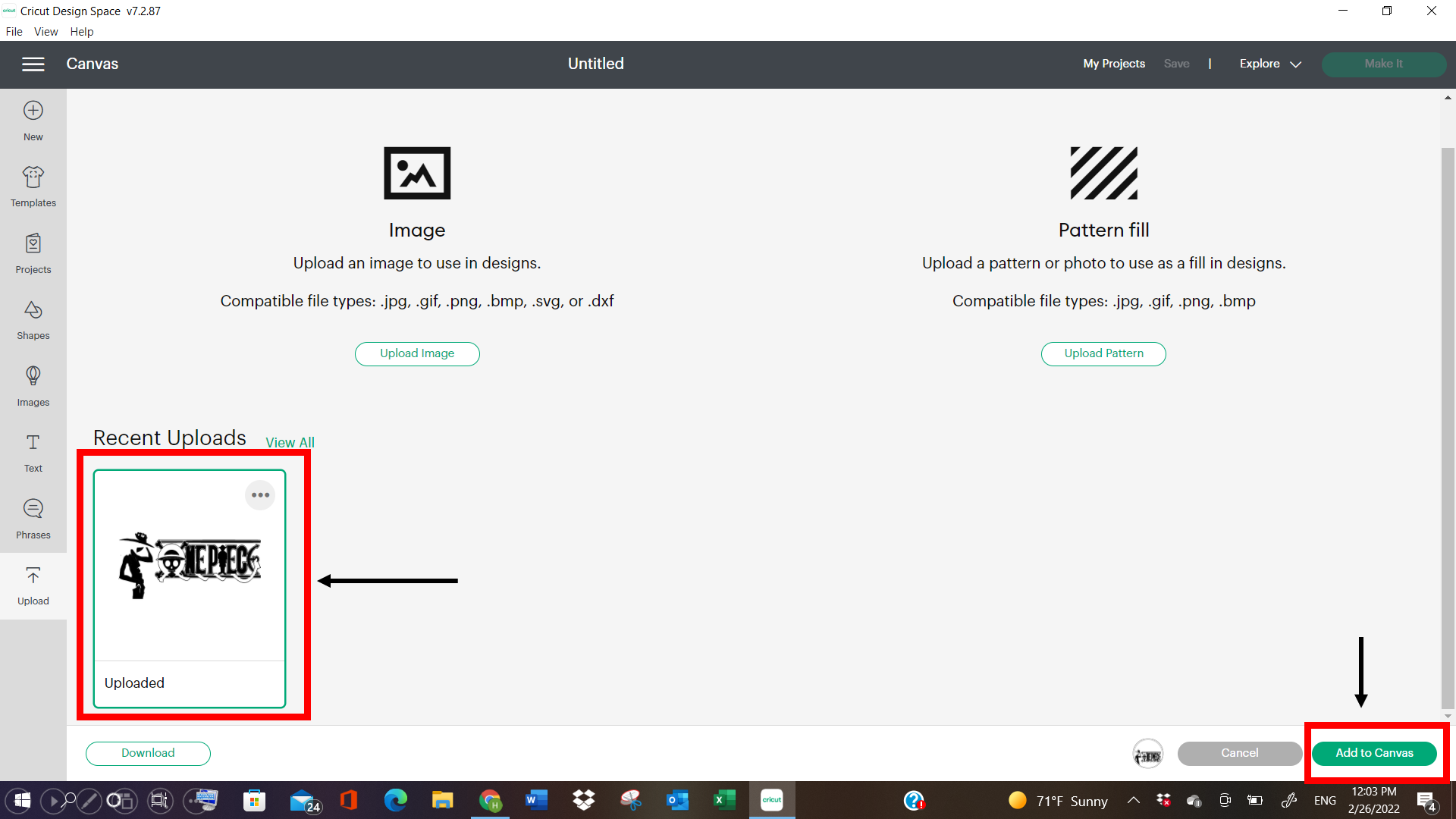
8- The I selected the image, and clicked on “Add to Canvas”.
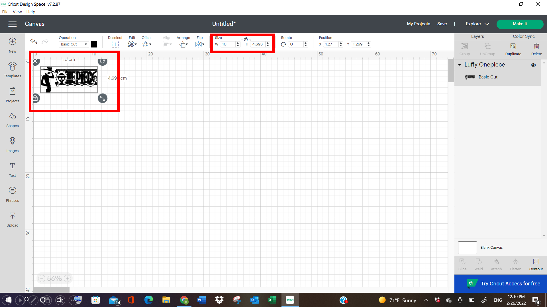
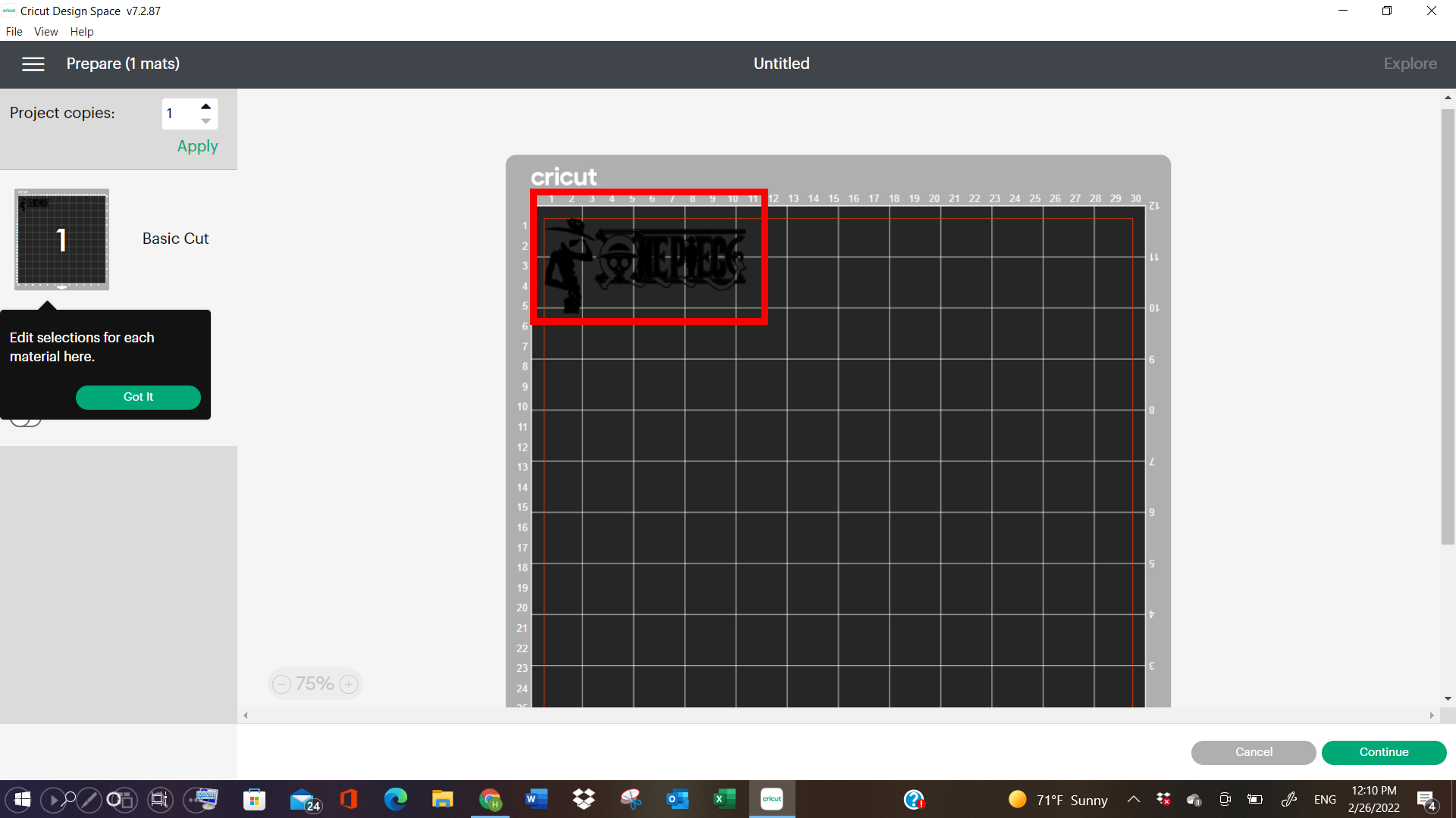
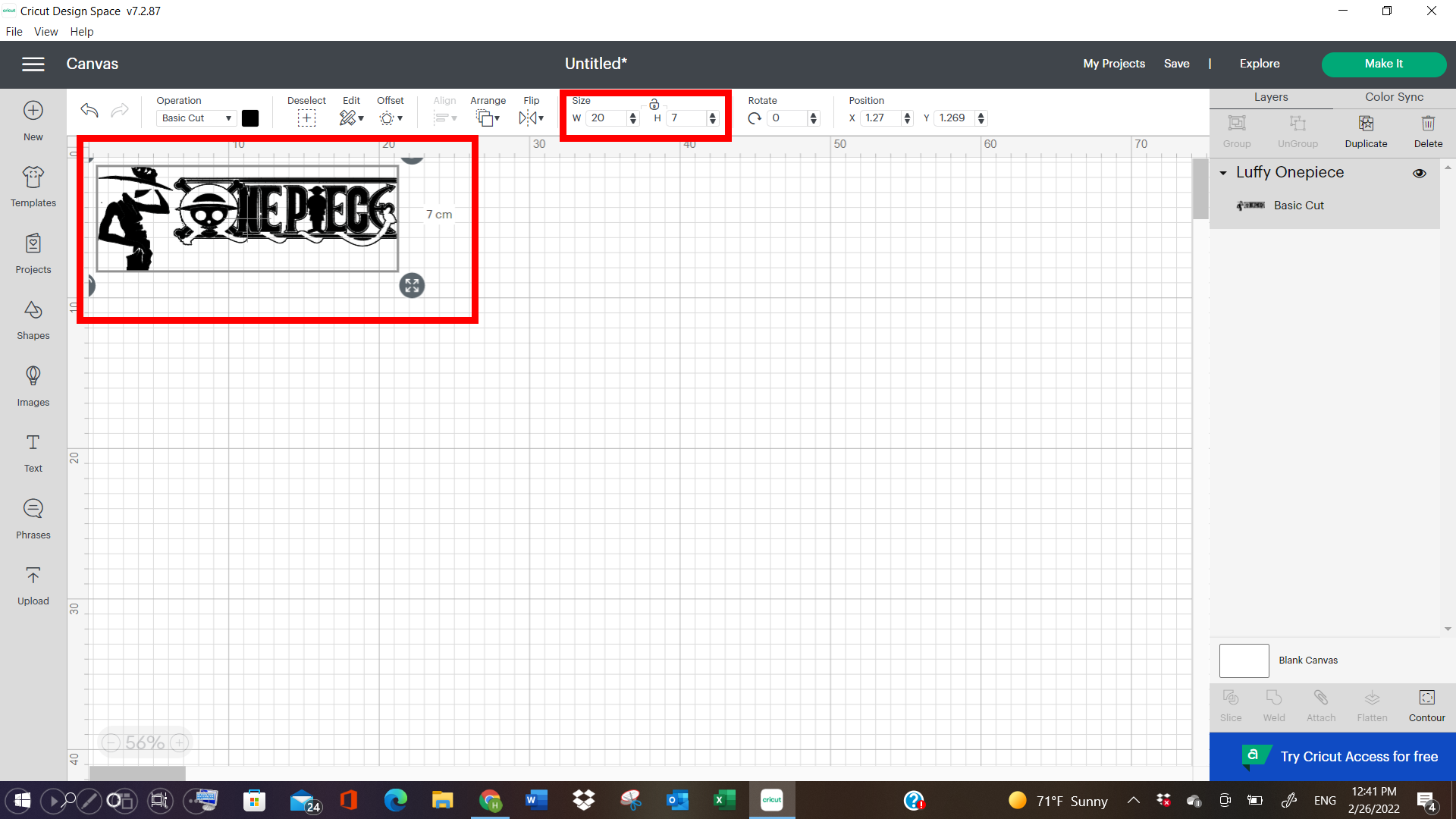
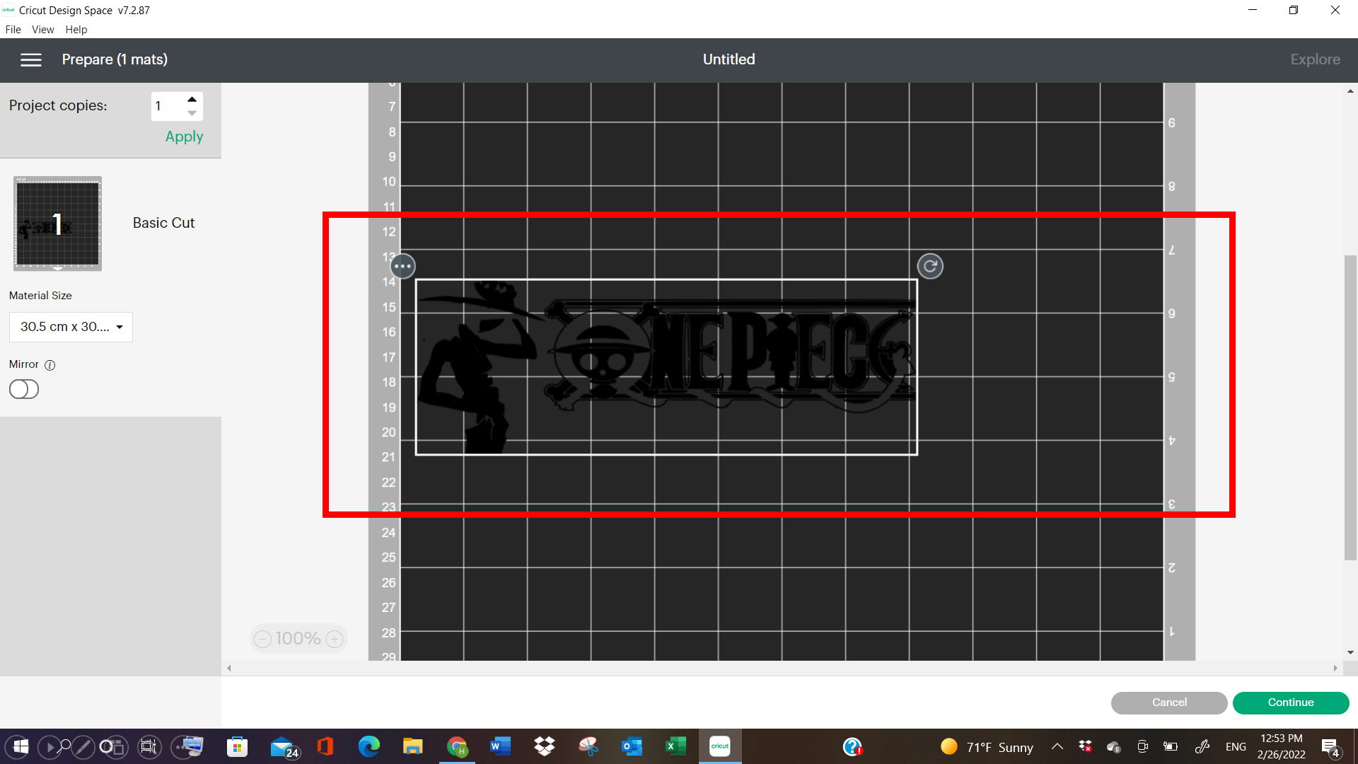
9- The image appeared on the screen, and I changed the size of it, accordingly, by comparing it with a scale, and seeing how much size I want it to be, in order to put on my laptop.
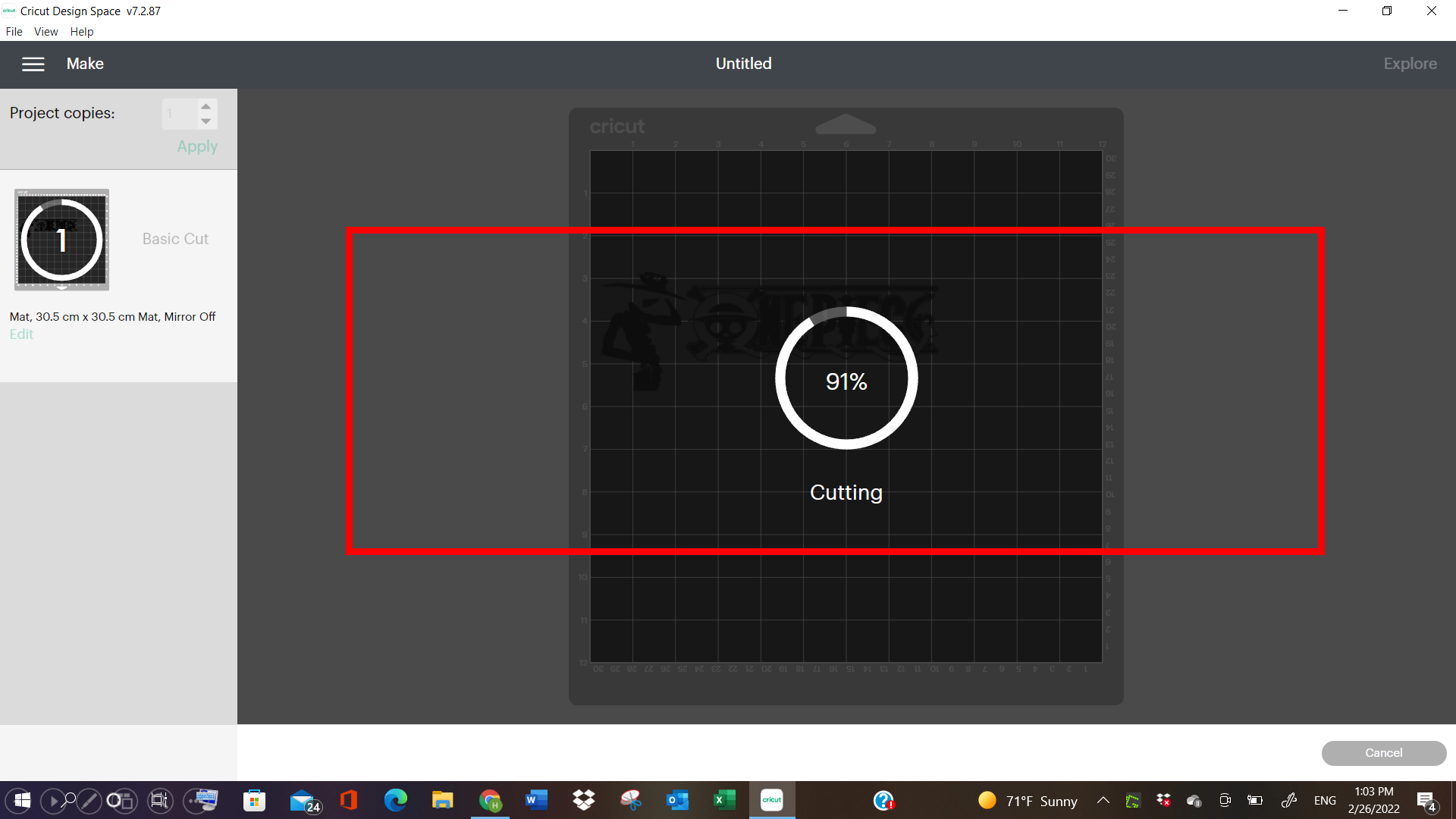
10- After, I fixed it at the edge of the paper, and started doing the cutting process.
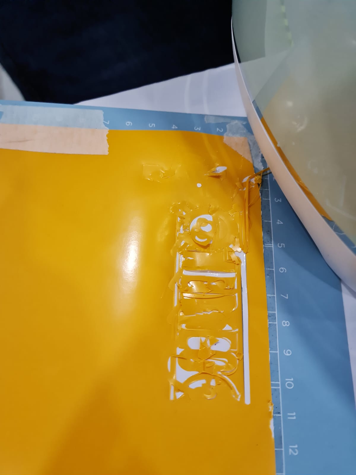
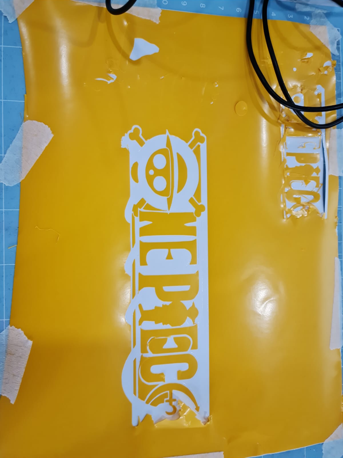
PROBLEM!
Because the scale size was very small, that is why the machine wasnt able to cut it correctly, and it had many loose paper ends, which made it hard to thin out the actual words.
Video
So, I started the process of sizing again, this time making it 20 in Width scale, instead of 10.
Final Video
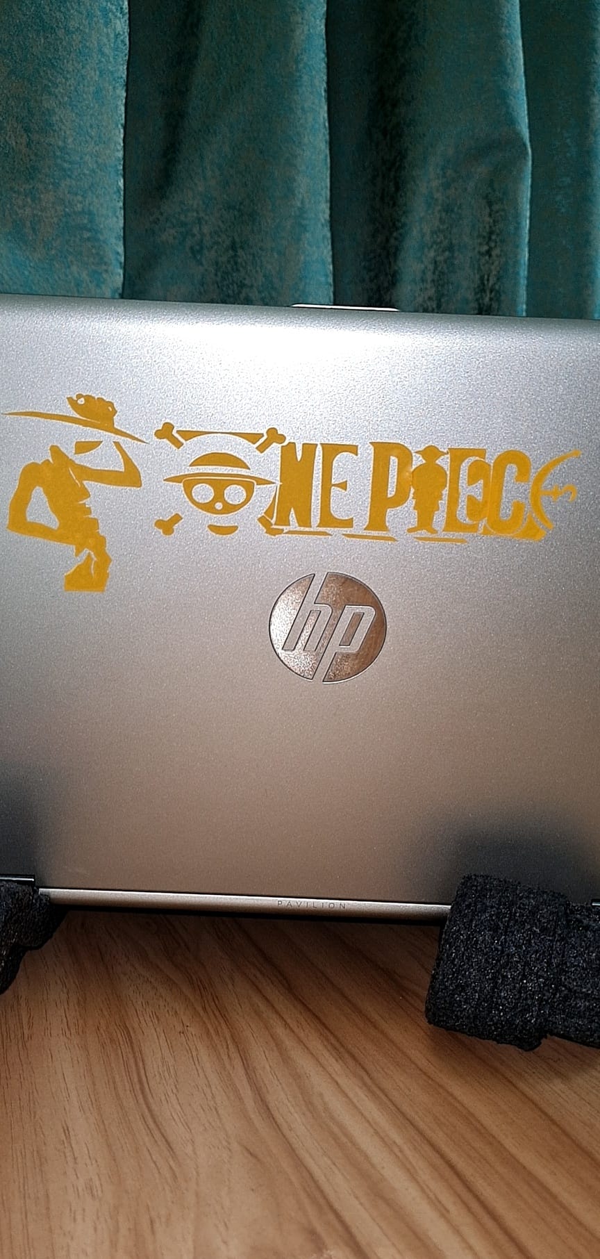
RESULT
Final results are much better.
LASER CUTTING (INDIVIDUAL ASSIGNMENT- PART 2)
Design and Lasercut a parametric press-fit construction kit
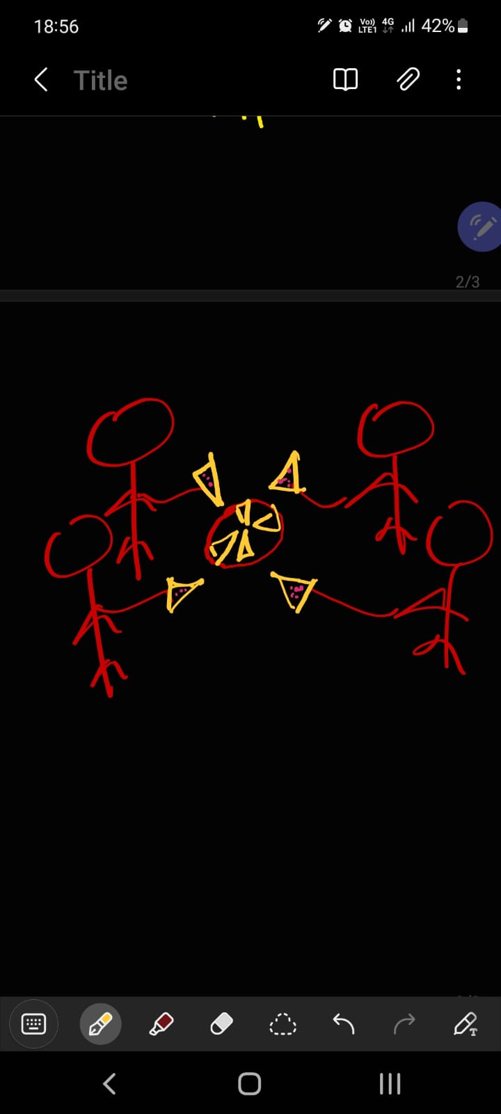
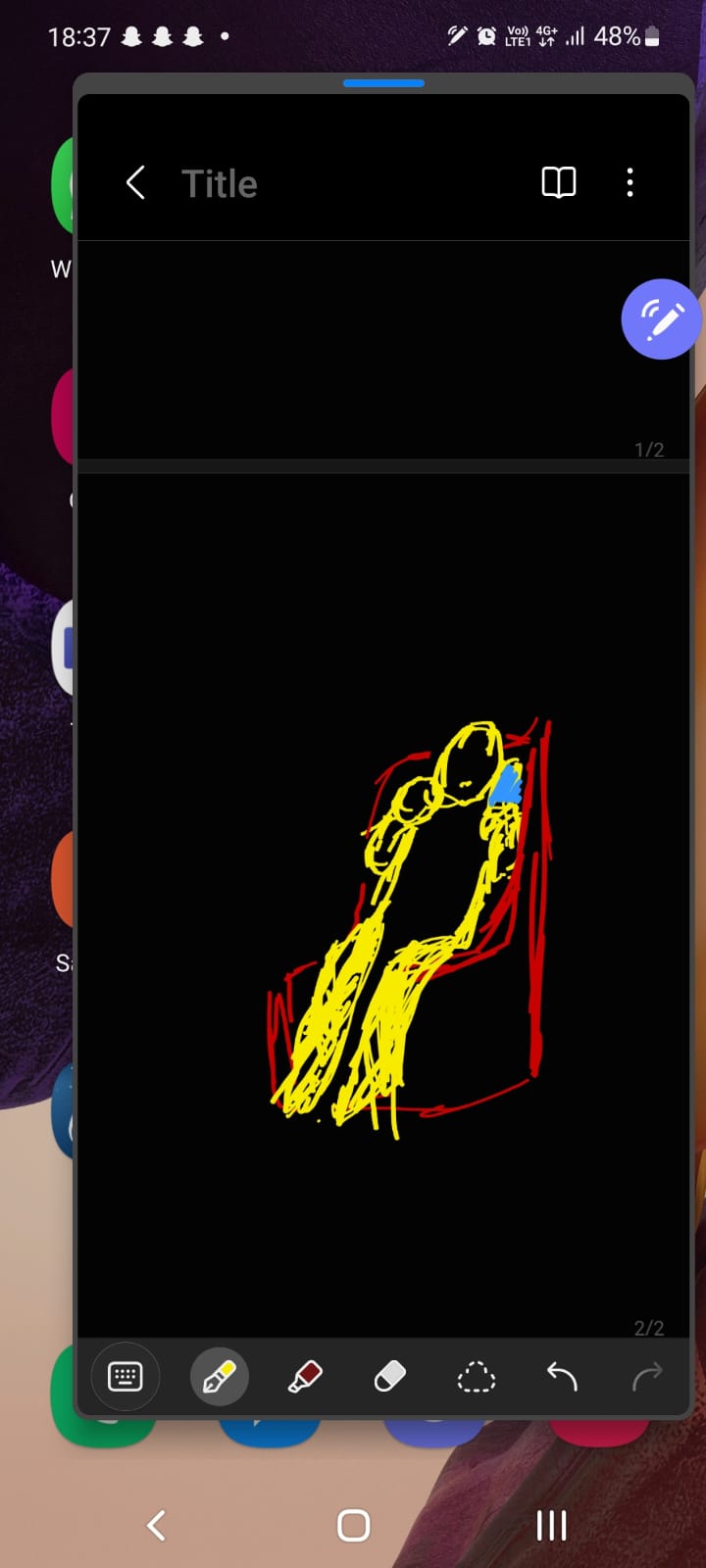
For the Laser cutting part, I started brainstorming for different ideas, for making my design, and started basic sketches of them in my phone.
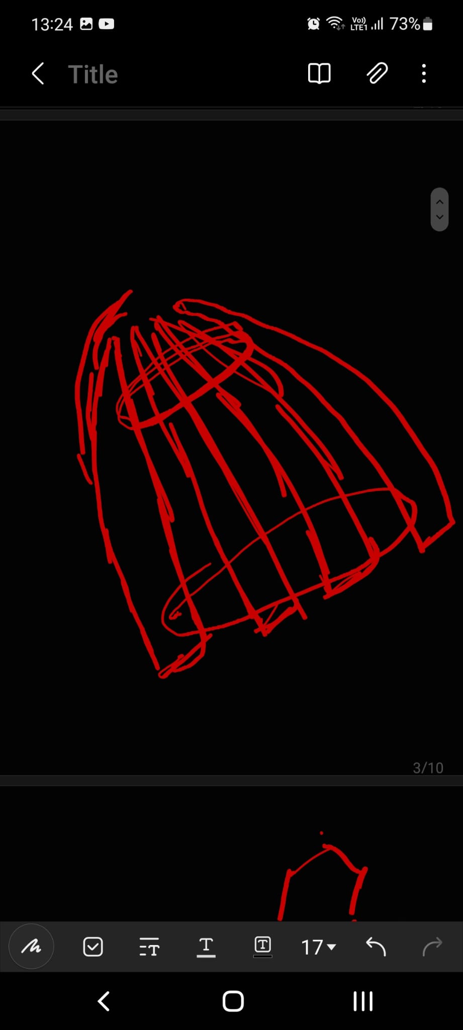
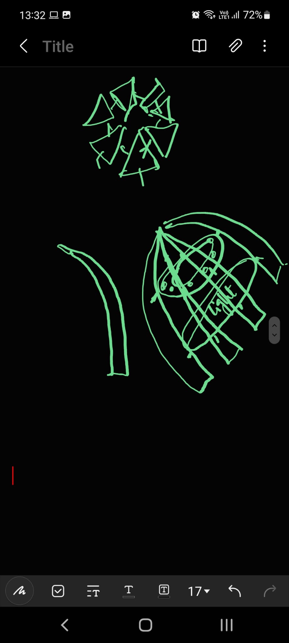
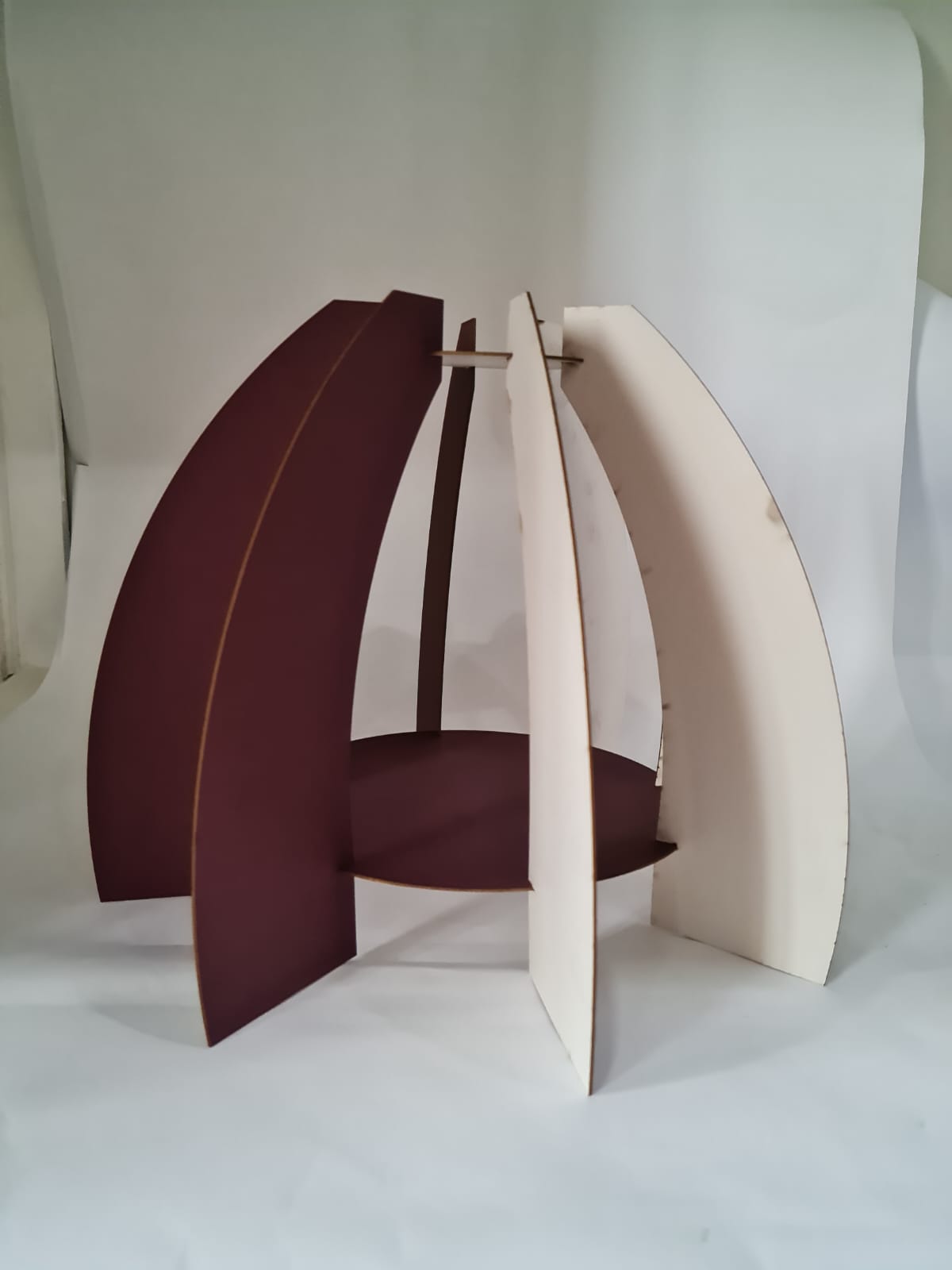
I wanted to do a dome-like structure, also kind of the representing the closure of a flower bud (as exposed to sunlights).
The design needs few shapes, such as :
1- One Big circle.
2- One Small circle.
3- 8 long curved shapes, that will be connected to those circles.
The material for the board is 0.8mm, as decided and stated earlier above.
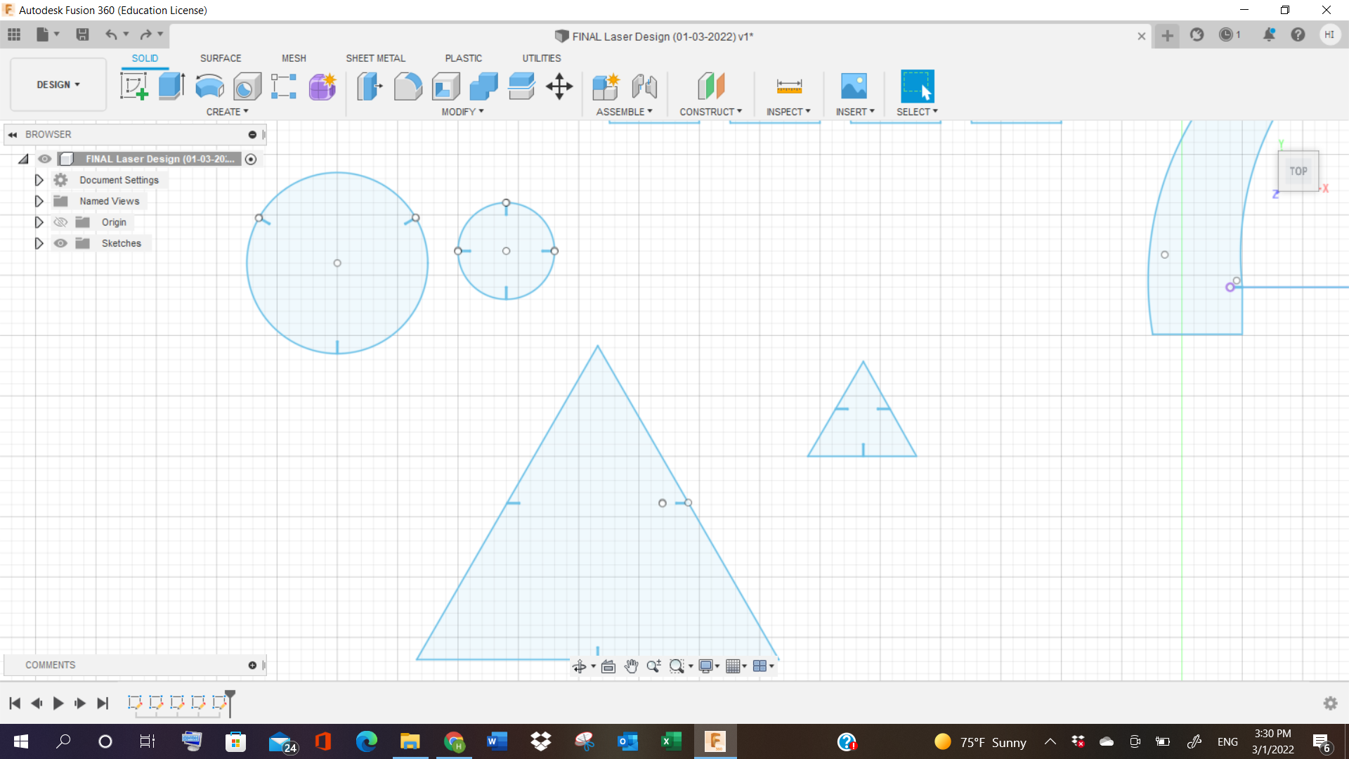
Design Process!
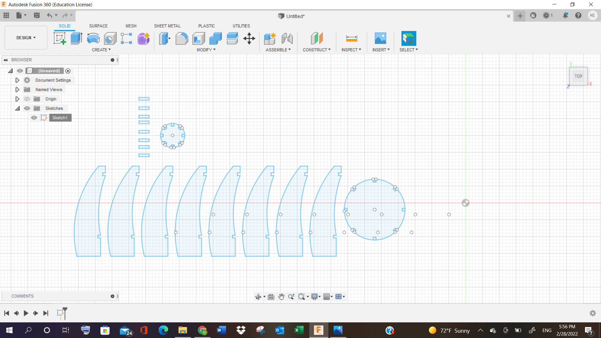
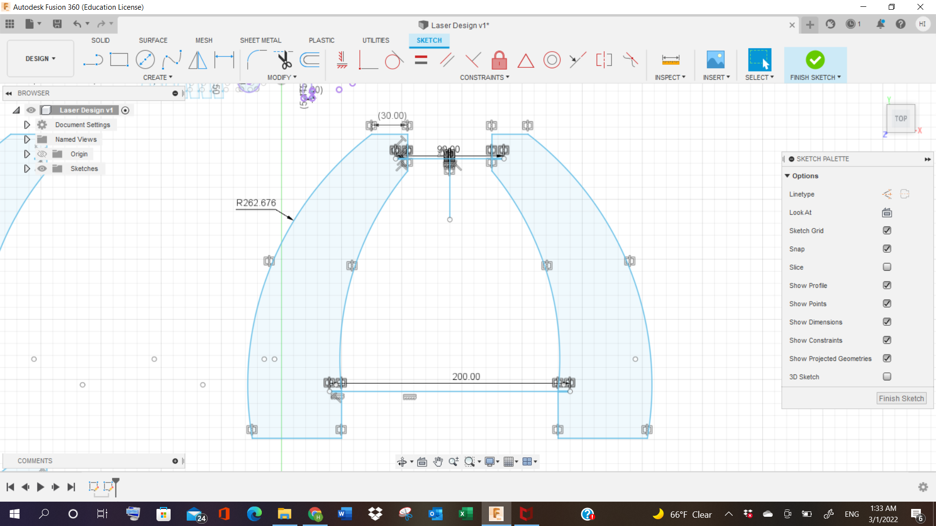
To do this, I started making the design in 2D in Fusion 360 (This software I have explained already in “3D Printing & Scanning” process).
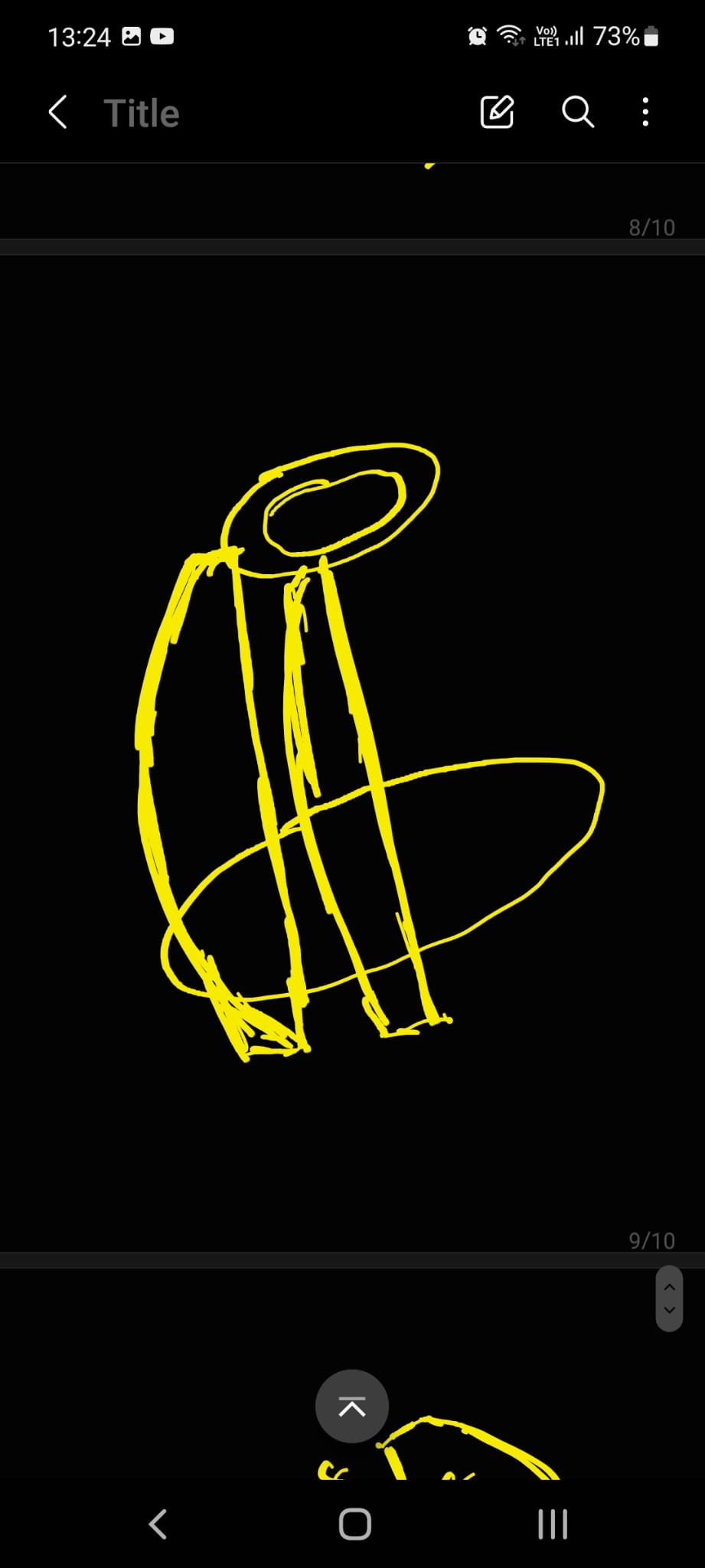
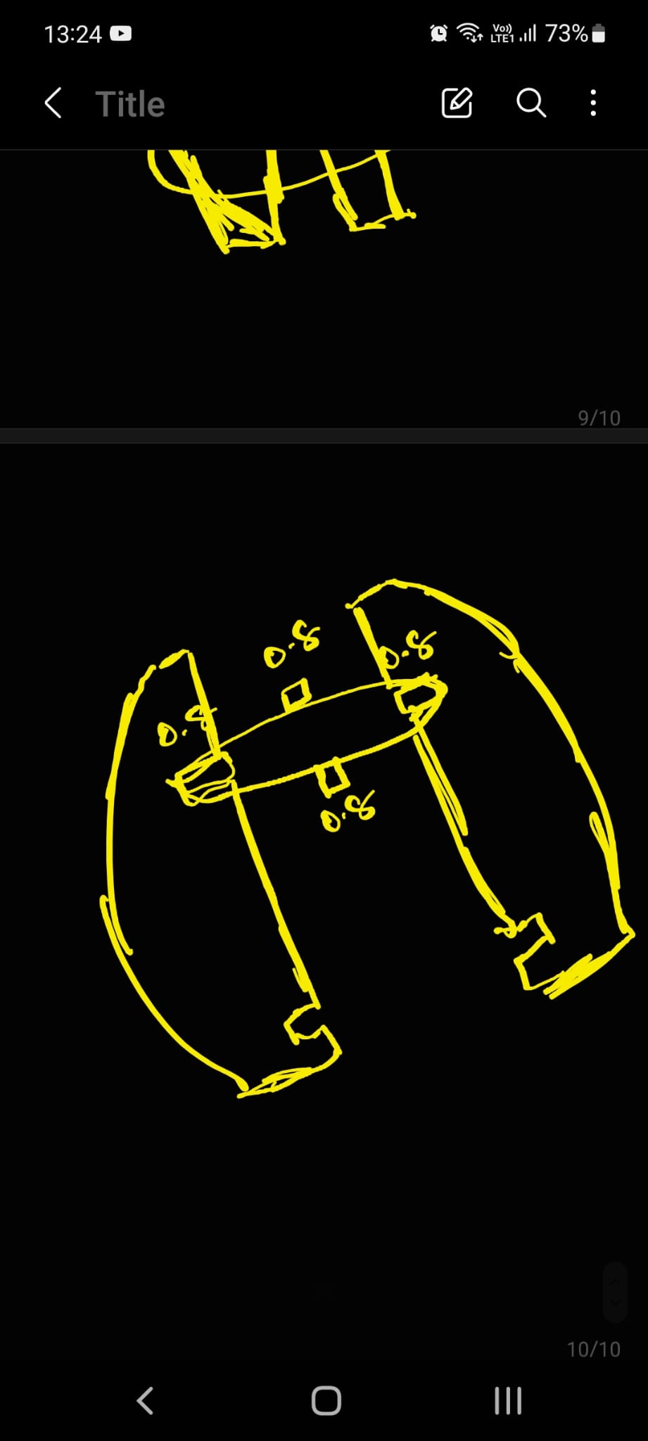
1- I first made the circles, both of different diameters, and started adding holes on the sides, with depth of “0.8mm” in it.
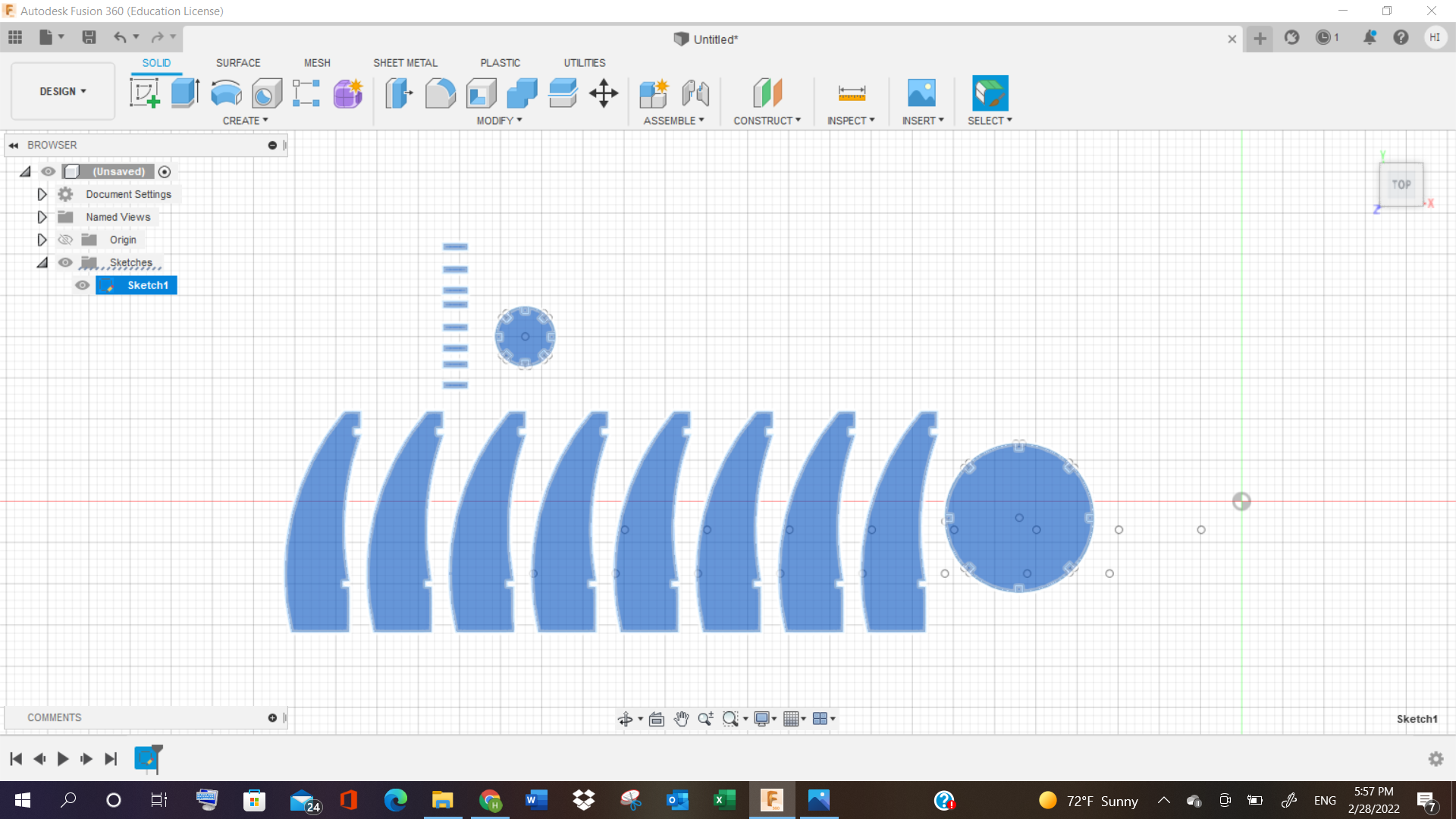
2- Next, I started making those cruved shapes randomly, in order to make it look like an enclosed space, and see if the structure fits with the circles.
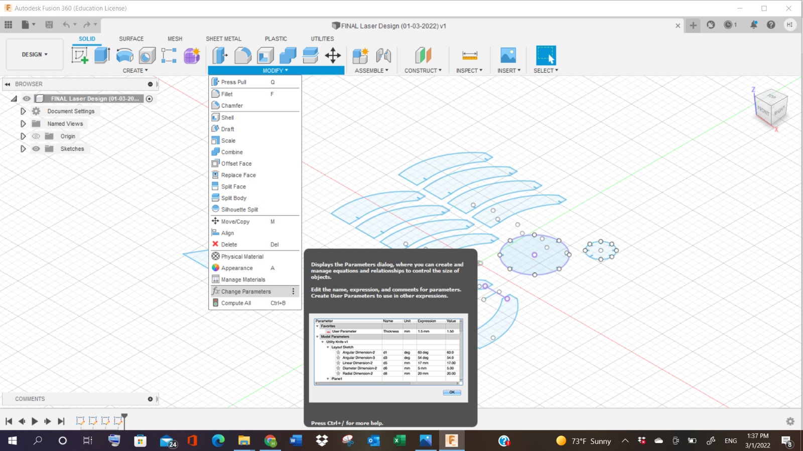
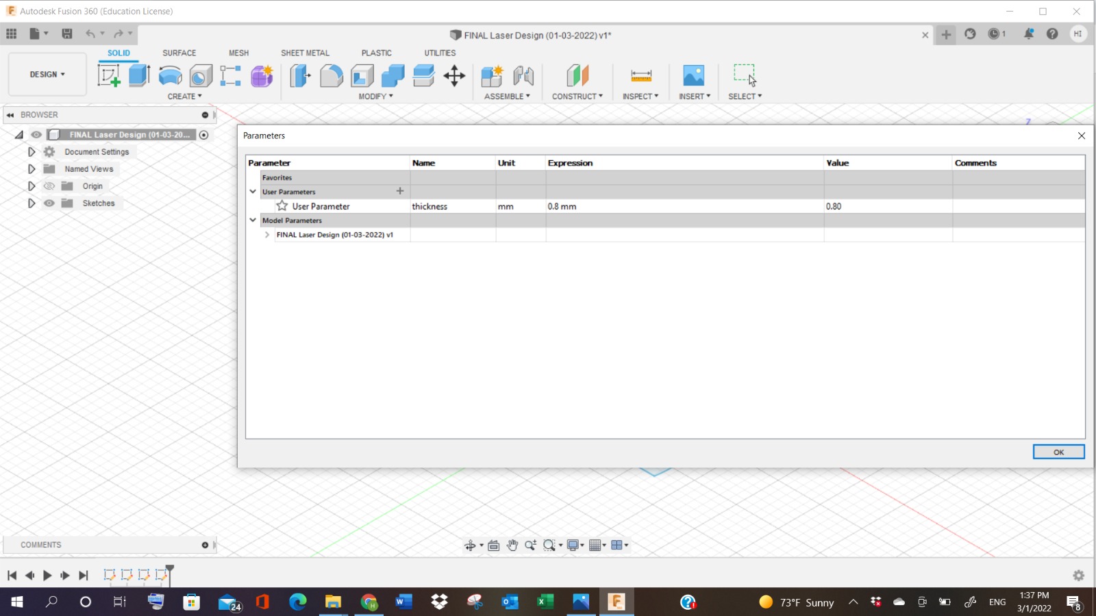
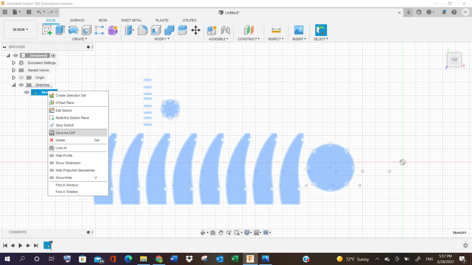
3- Then I thought of making small joints, that will connect both the curved shapes and the circles together. Key point to note, that I went to the “parameter table”, and made a new “user parameter”, giving it the name of “thickness” having “0.8mm” value.
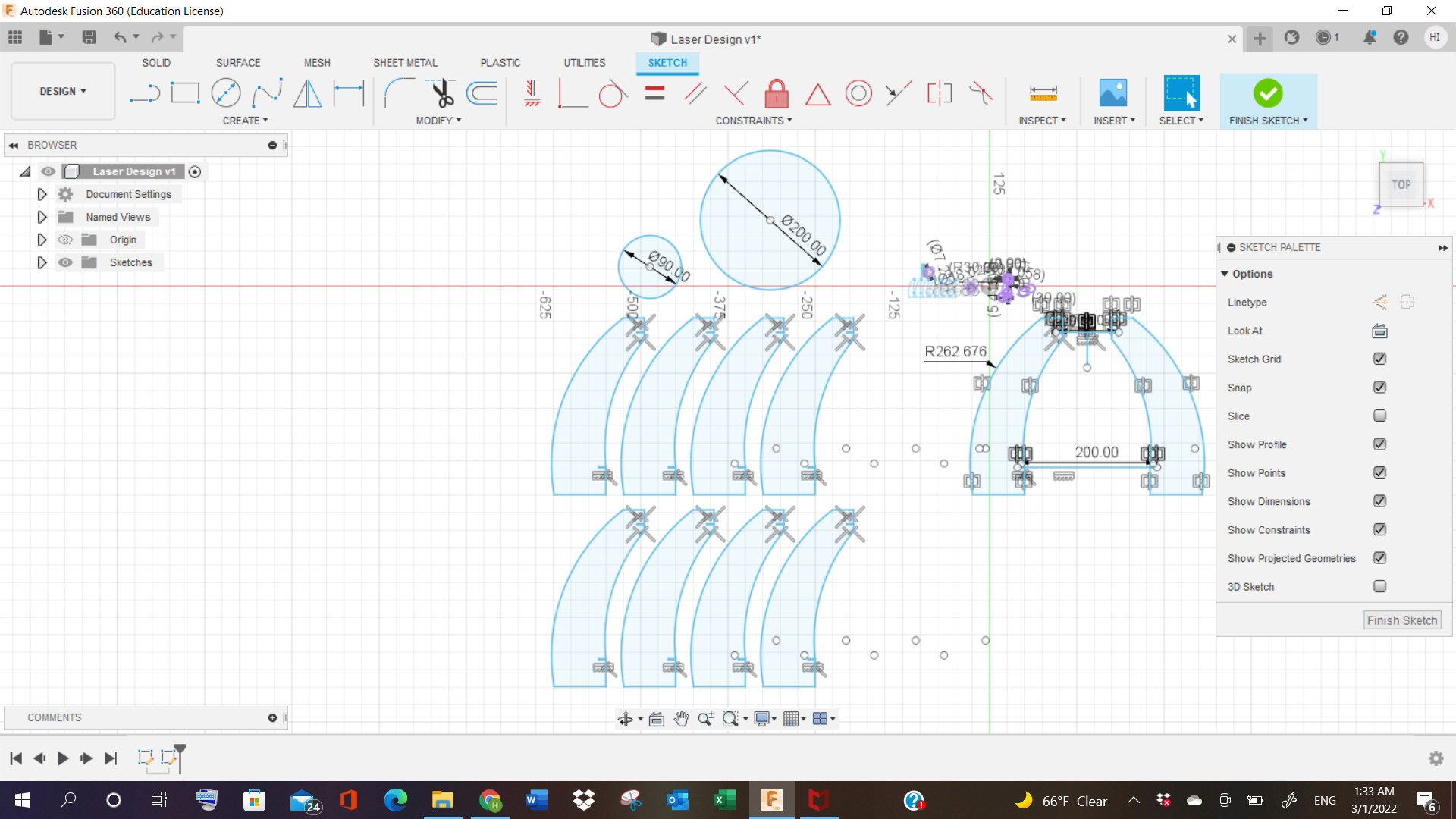
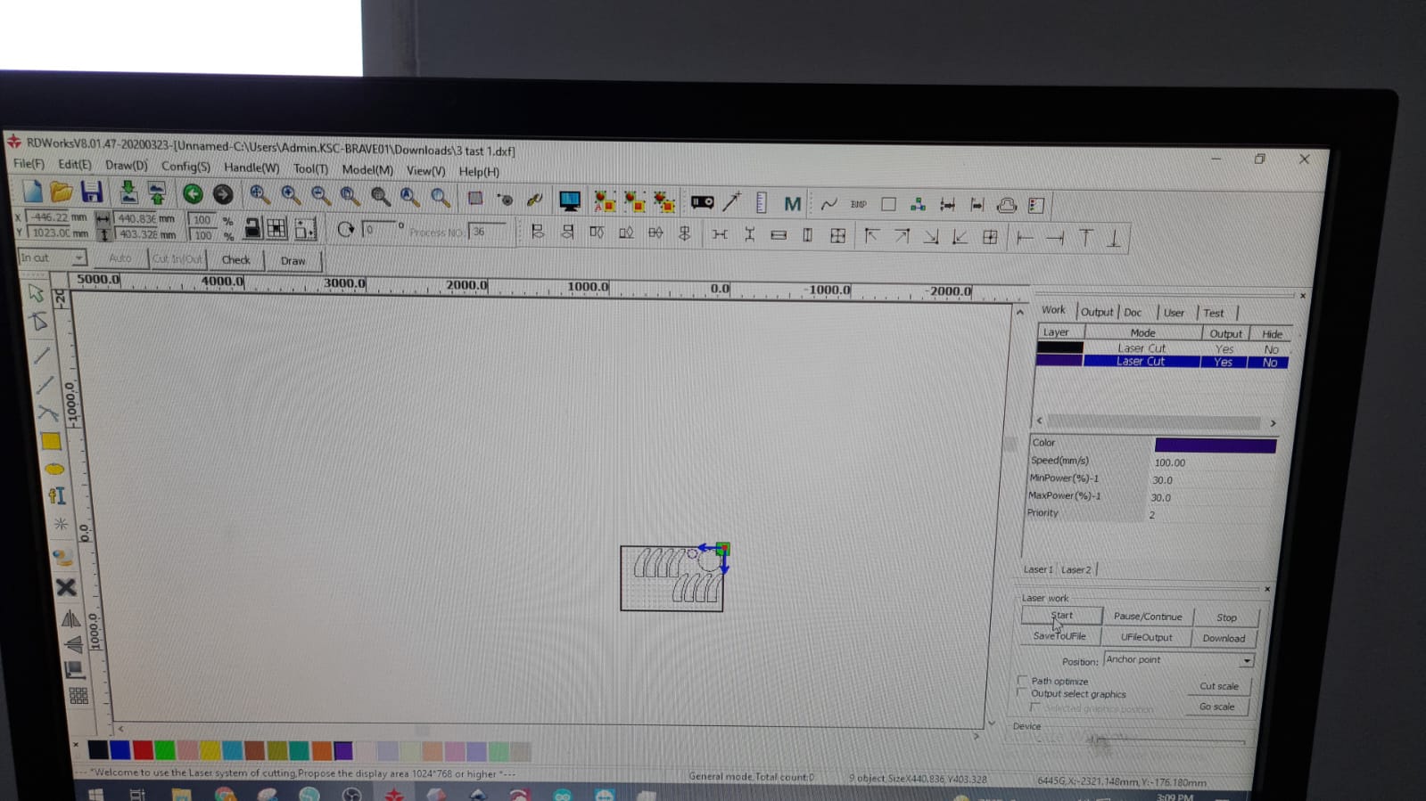
4- After I made the design, I went to “Sketch”, did “right-click” on it, and selected “Save as dxf file”. I imported the work to RD works on PC, and started making the parameter changes.
5- BUT, when put in the sheet layout, the objects appeared really small, indicating that the design to be cut, will be very small in scale.
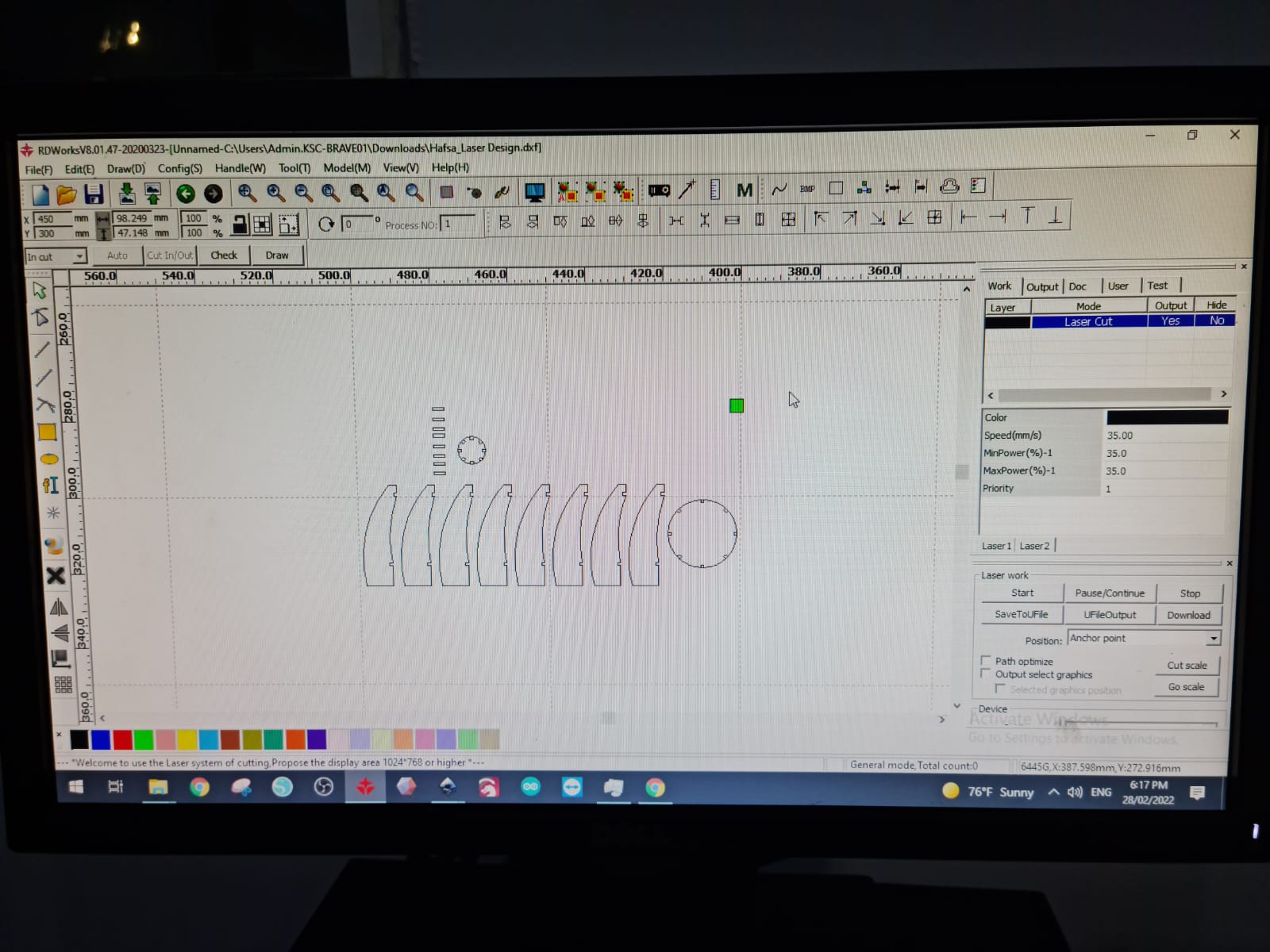
PROBLEM!!!!
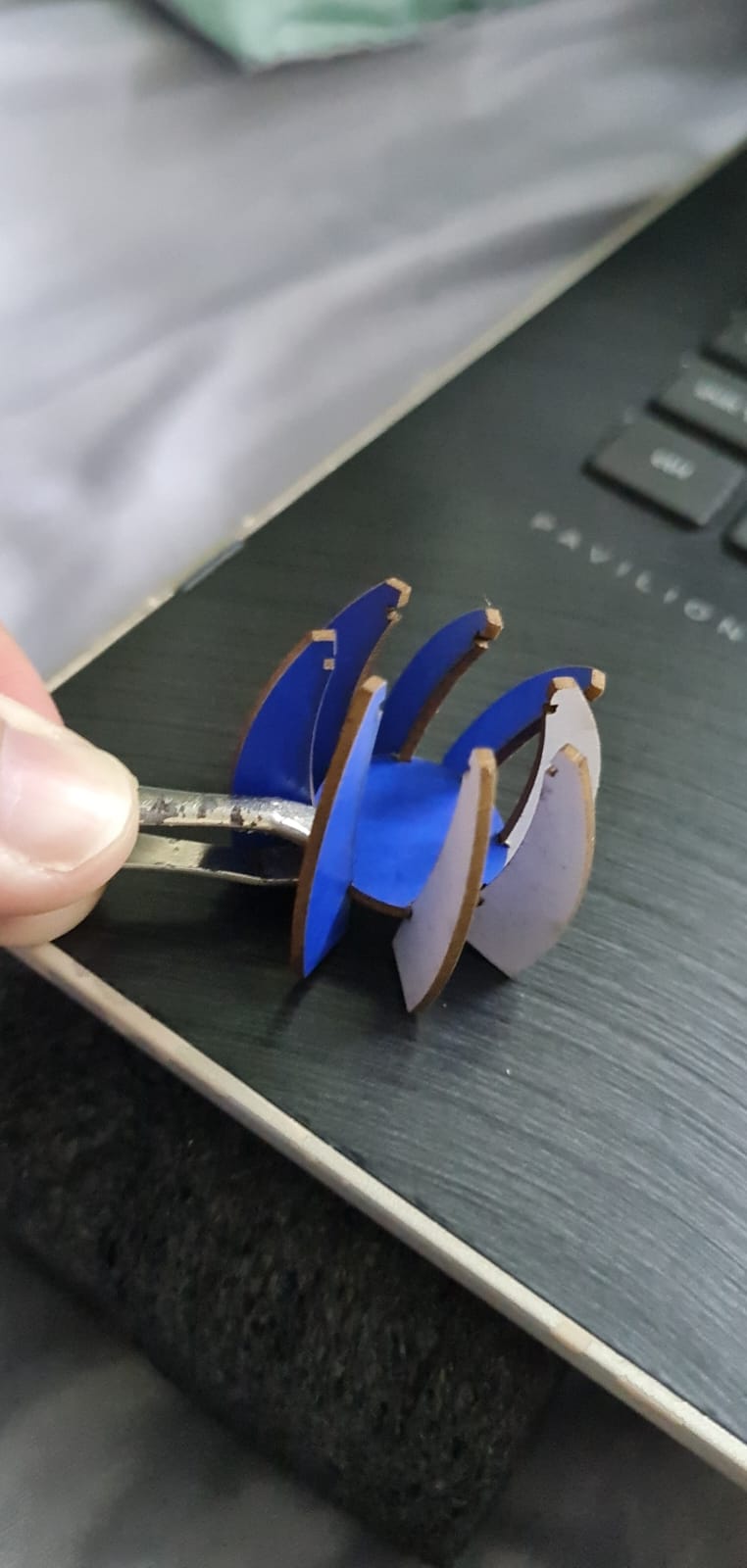
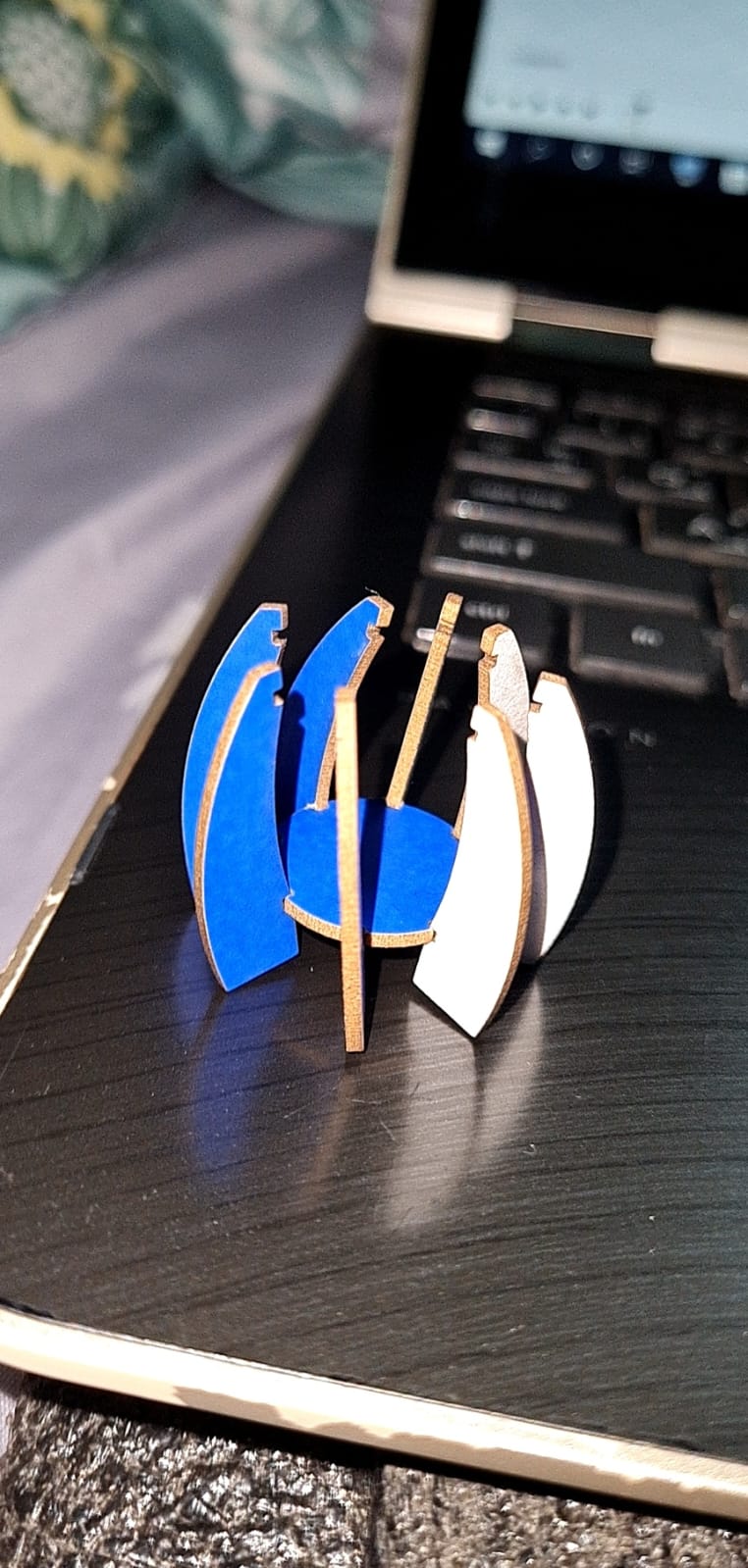
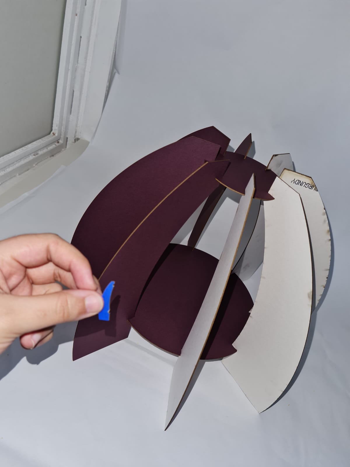
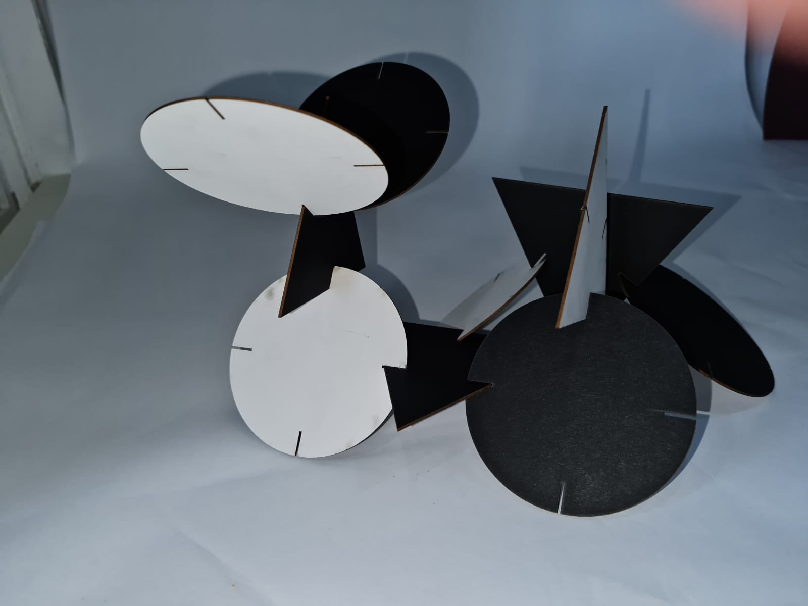
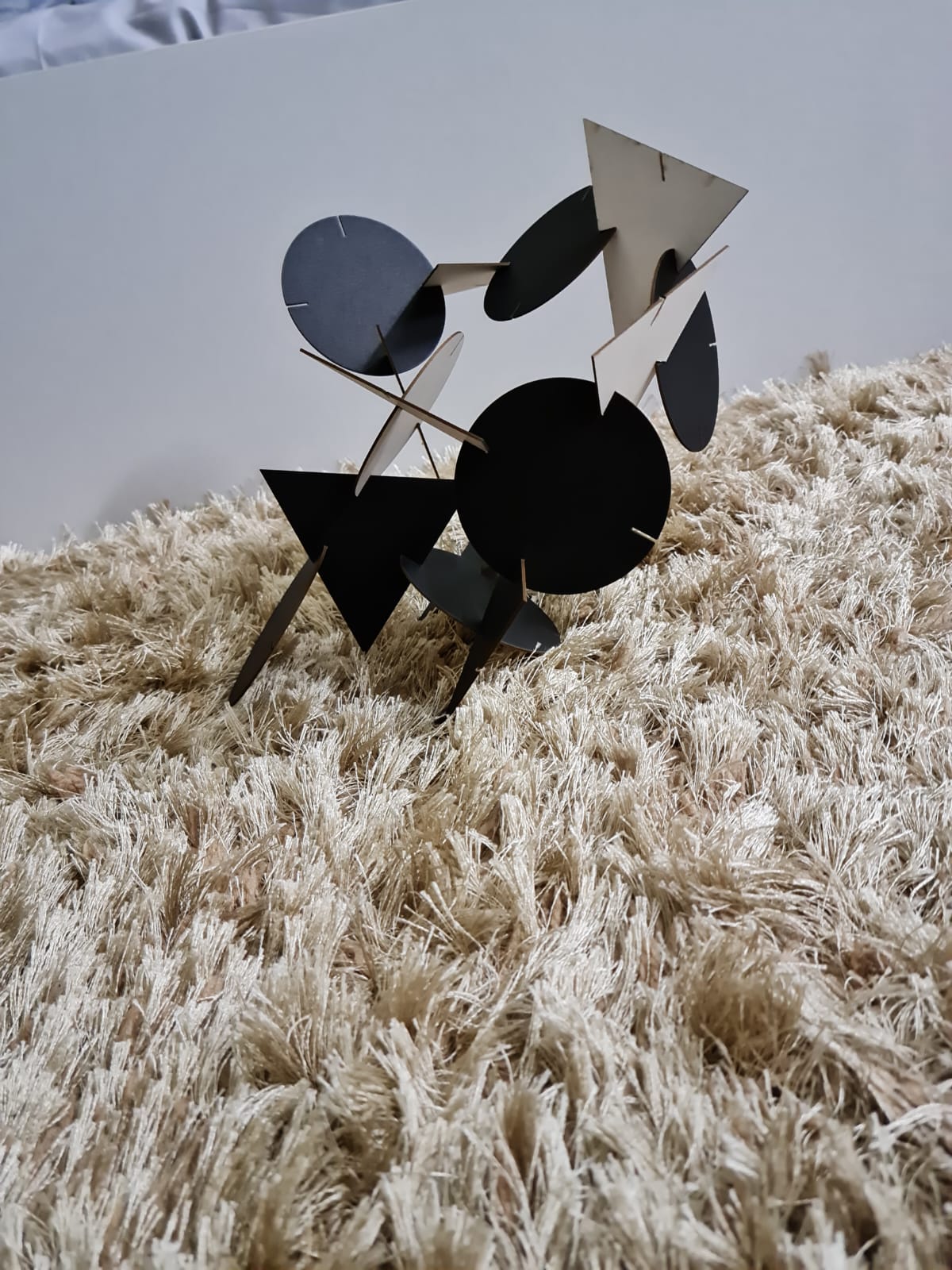
Now, since the design was small in scale, the joints that I had made were very small, and hence fell into the insides of the machine. One small circle fell inside too. The remaining objects that I could salvage were the curved shapes and the big circle that would bind them together.
However, since they were small in scale, it was difficult to connect and join them, because one or the other shapes would then fall off.
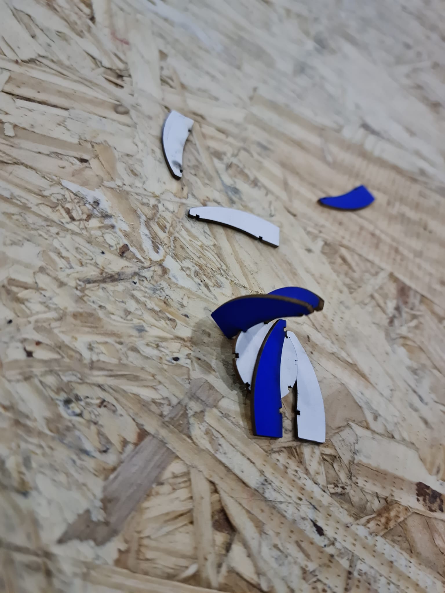
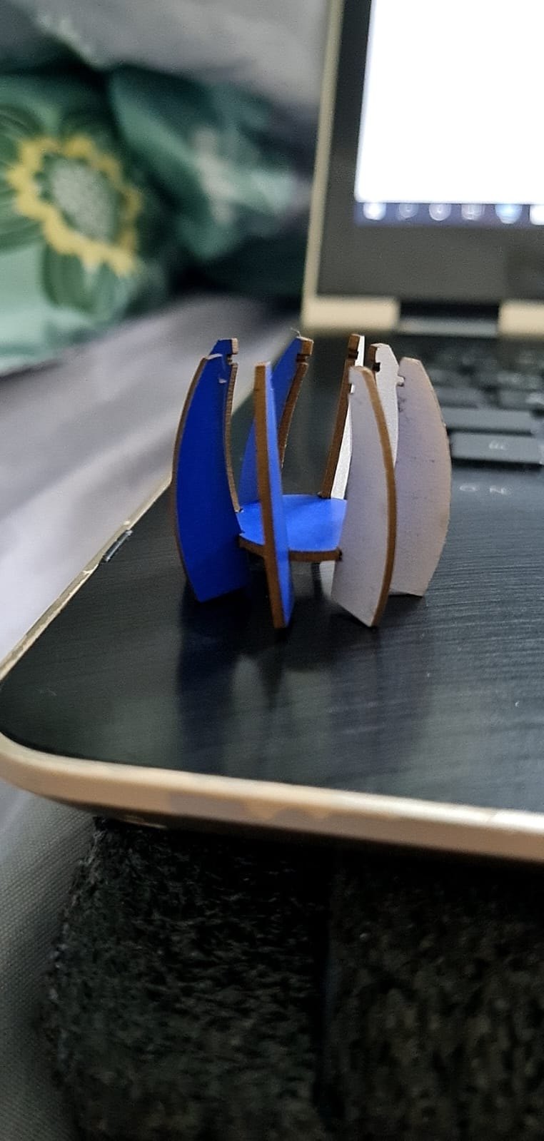
I tried joining the pieces again at home, and somehow, after great difficulty, they joined, and I took the pictures of it.
Video (1st Try!)
2nd TRY!!
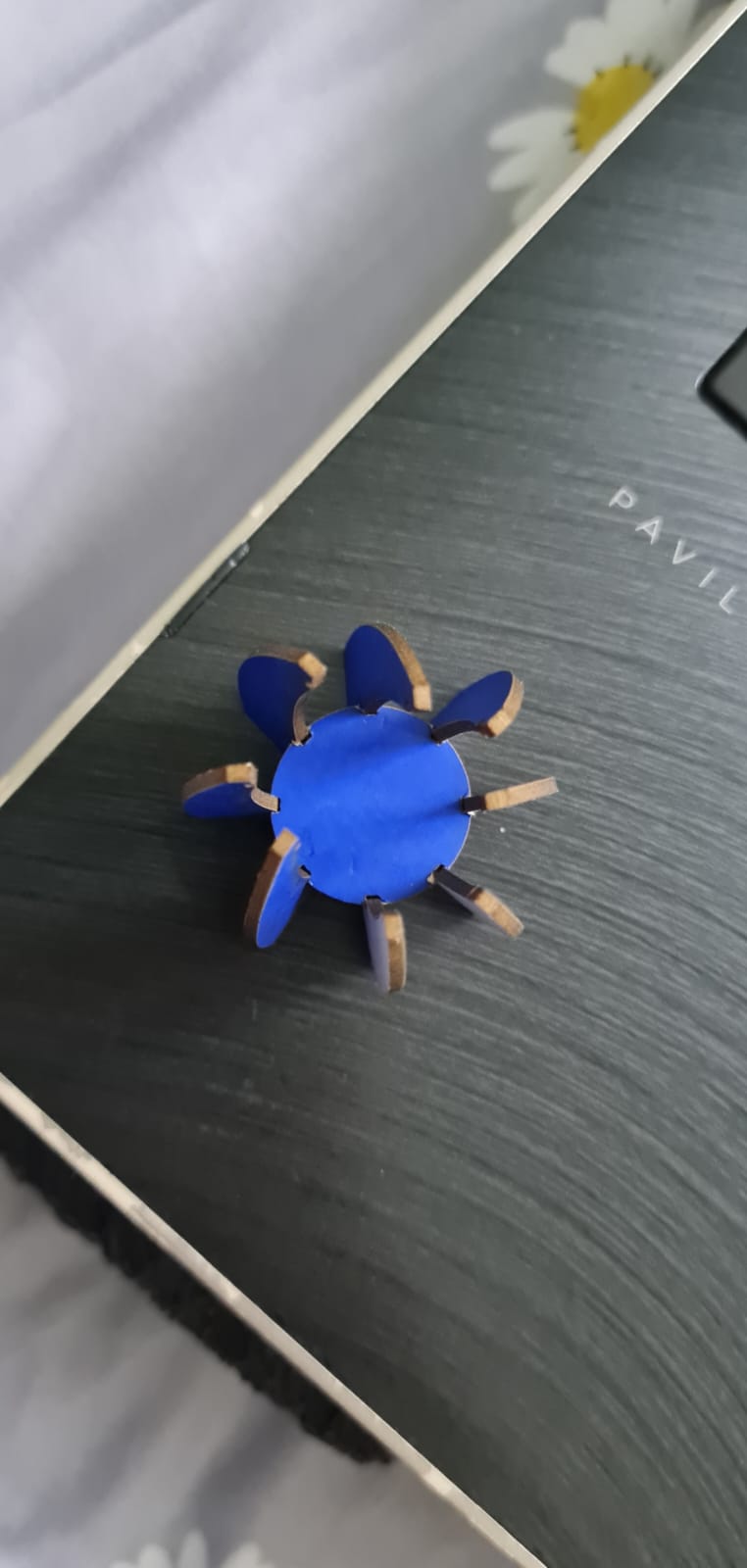
So, I decided to change the scale and measurements of my objects, and try laser cutting it again on the next day. Hopefully, the size is better this time, for it to be seen correctly.
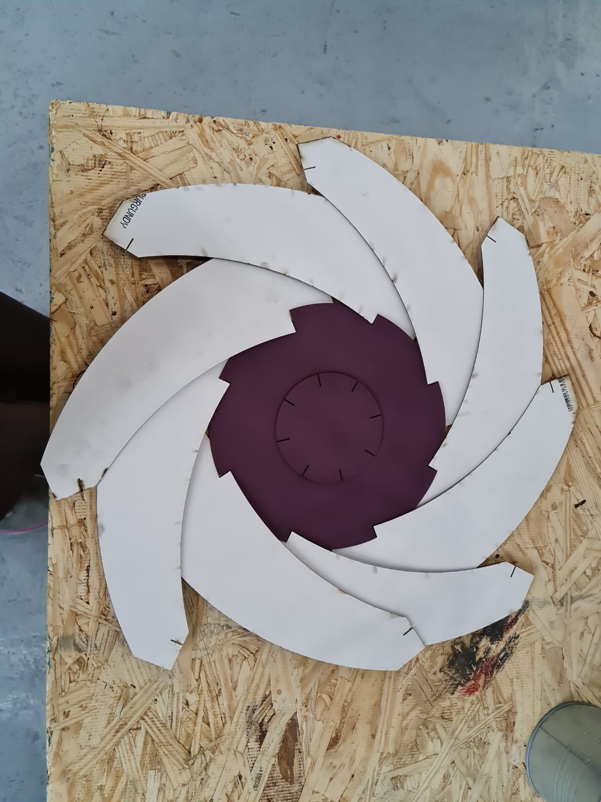
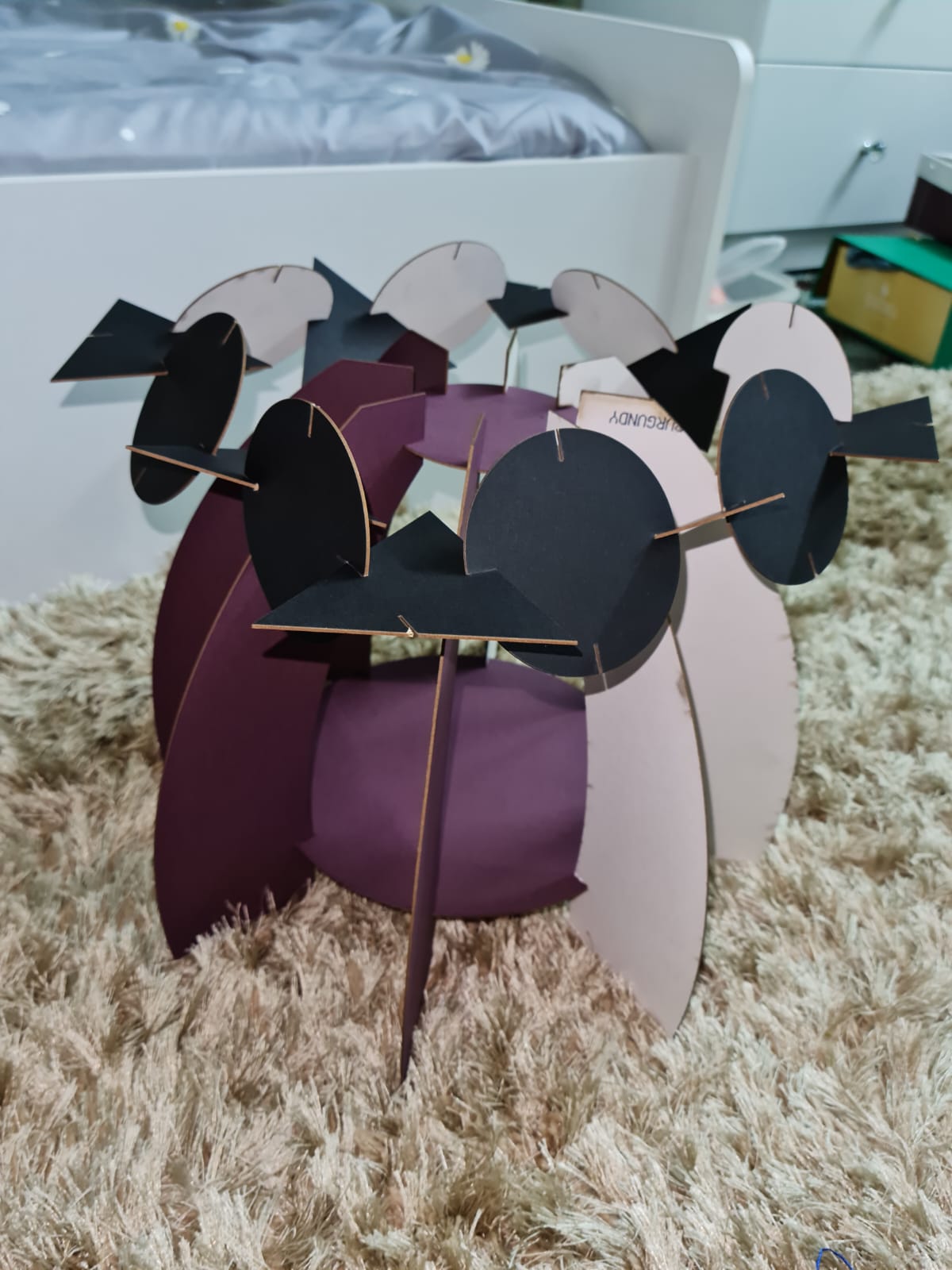
This time, for the shapes, I increased the measurements of the curves and the circles by 10x times fold, and started making the shapes. I didn’t make the joints, as I noticed that the curved shapes can still stick with the circles just fine.
So, this time, I made:
1- One Big circle.
2- One Small circle.
3- 8 curved shapes, to be connected to those circles.
4- I did the export process as dxf file again.
5- And then, I sent the file via email to Fablab, and get it ready for cutting.
6- The parameters I forgot to change, because of which there is slight burning seen on the sides, as it became:
Speed = 100
Power = 30
video
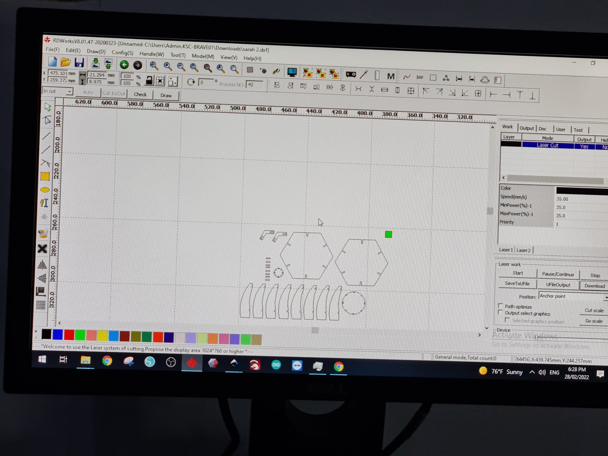
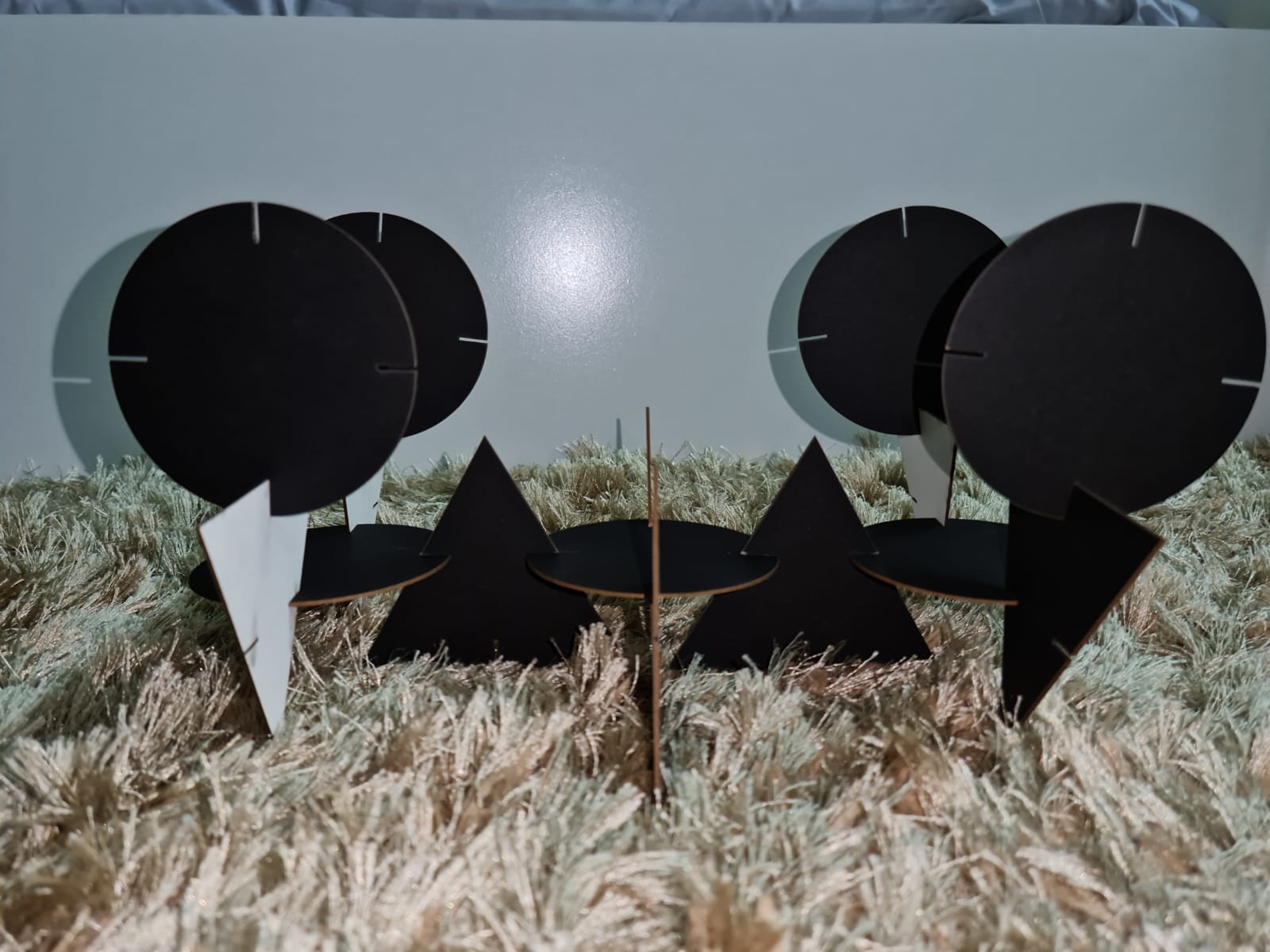
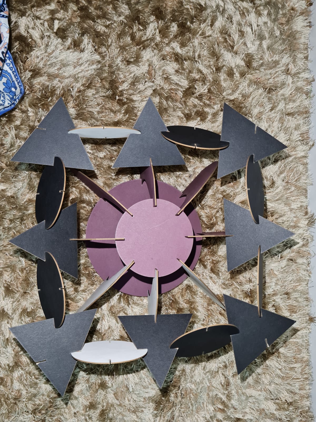
Another Press-fit Construction Design
Just in case, I decided to make another design, in case the previous one still doesn’t come properly in shape.
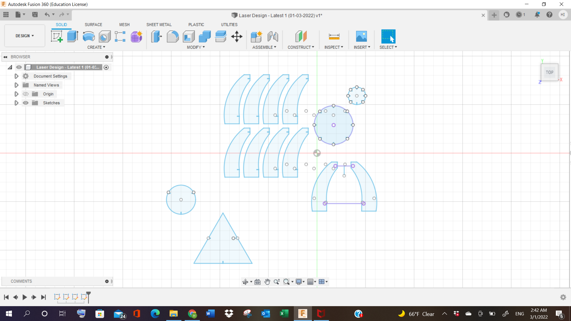
For this, I made the following shapes:
1- 8 triangles.
2- 8 circles.
I exported them as dxf files, and sent it to PC.
I copy pasted them in RD works software, and this time, I made the settings properly, i.e.
Speed: 25
Power: 35
And, I started laser cutting them.
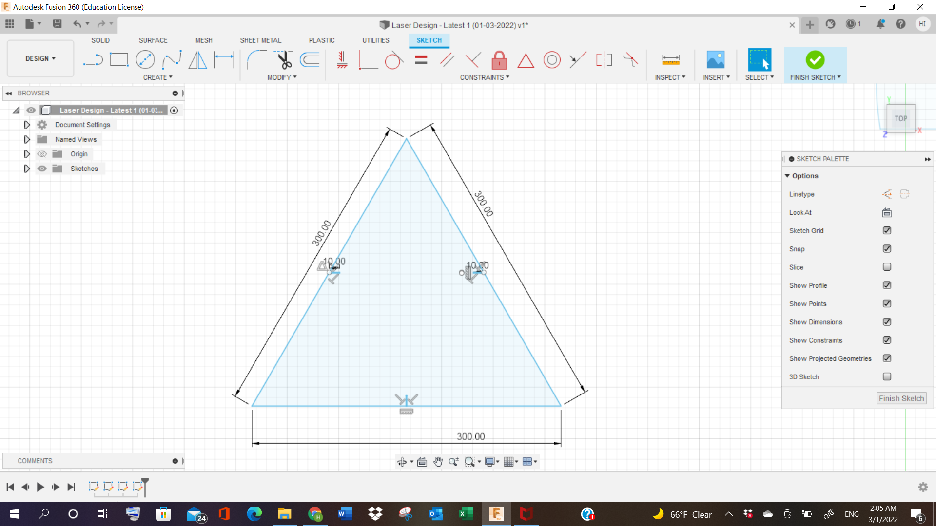
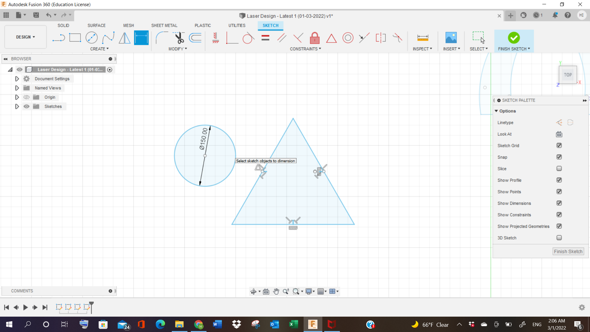
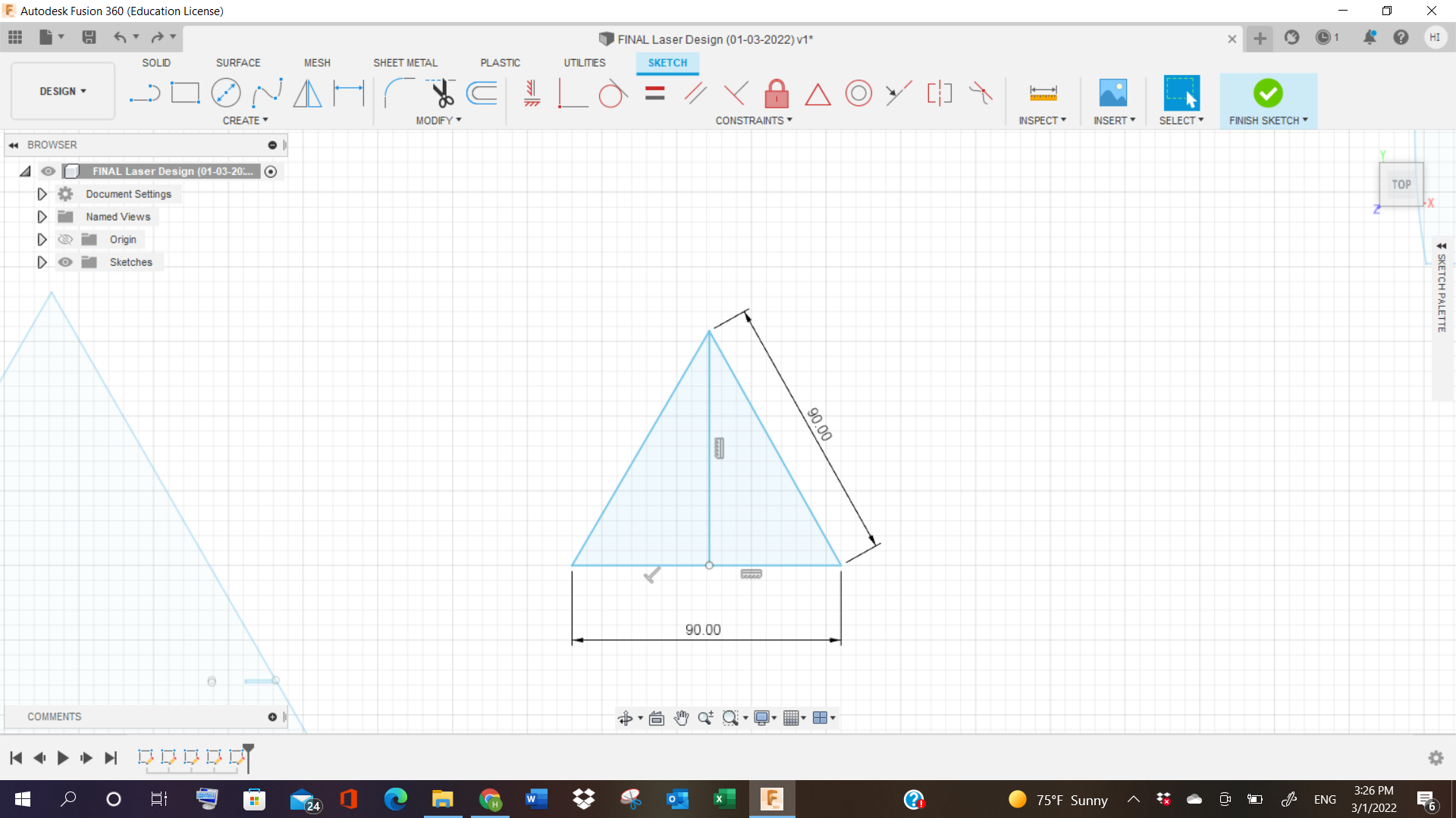
The size of it was very large, so I reduced the size again in Fusion 360. This time, the diameter of circle was 80 (instead of 150), and triangles were 90 (instead of 300), and tried importing it again.
Video (2nd Try!)
DXF files
Here are the dxf files, where you can download the design.
Fusion360 file
Laser Cutting - Both Design files