6. Embedded Programming
This week we explored and learned about microcontrollers and implemented programming using Arduino IDE & Mu Editor.
Group assignment:
- Search for different types of microcontrollers boards and compare between them.
- Search for different programming languages, compare between them and how many can you use to program the same microcontrollers.
Individual assignment:
- Read the datasheet for the microcontroller board you are programming
- Program the board you have to do something, with as many different programming languages and programming environments as possible. (two at least)
Group Assignment
The group assignment we searched and explored different types of microcontrollers boards and compared between them, and we looked at different programming languages, compared between them and how many can we use to program the same microcontrollers. All the information are combined in this link.
Individual Assignment
What is Embedded System?
Embedded system is a combination of hardware and software designed for a selected function. The systems are often programmable and fast functionality. It is a controller programmed by a real-time operating system with a dedicated function within an electrical system, often with real-time computing constraints.
Embedded systems are managed by microcontrollers or digital signal processors, application-specific integrated circuits, field-programmable gate arrays, and circuit arrays. These processing systems are integrated with components dedicated to handling electric or mechanical interfacing. Embedded systems connect with surface of world through peripherals, linking input and output devices.
About Microcontrollers
A microcontroller is a compact integrated circuit designed to govern a specific operation in an embedded system. A typical microcontroller includes a processor, memory and input/output (I/O) peripherals on a single chip.
A microcontroller is embedded inside of a system to control a singular function in a device. It does this by interpreting data it receives from its I/O peripherals using its central processor. The temporary information that the microcontroller receives is stored in its data memory, where the processor accesses it and uses instructions stored in its program memory to decipher and apply the incoming data. It then uses its I/O peripherals to communicate and enact the appropriate action.
From Microcontroller Datasheet
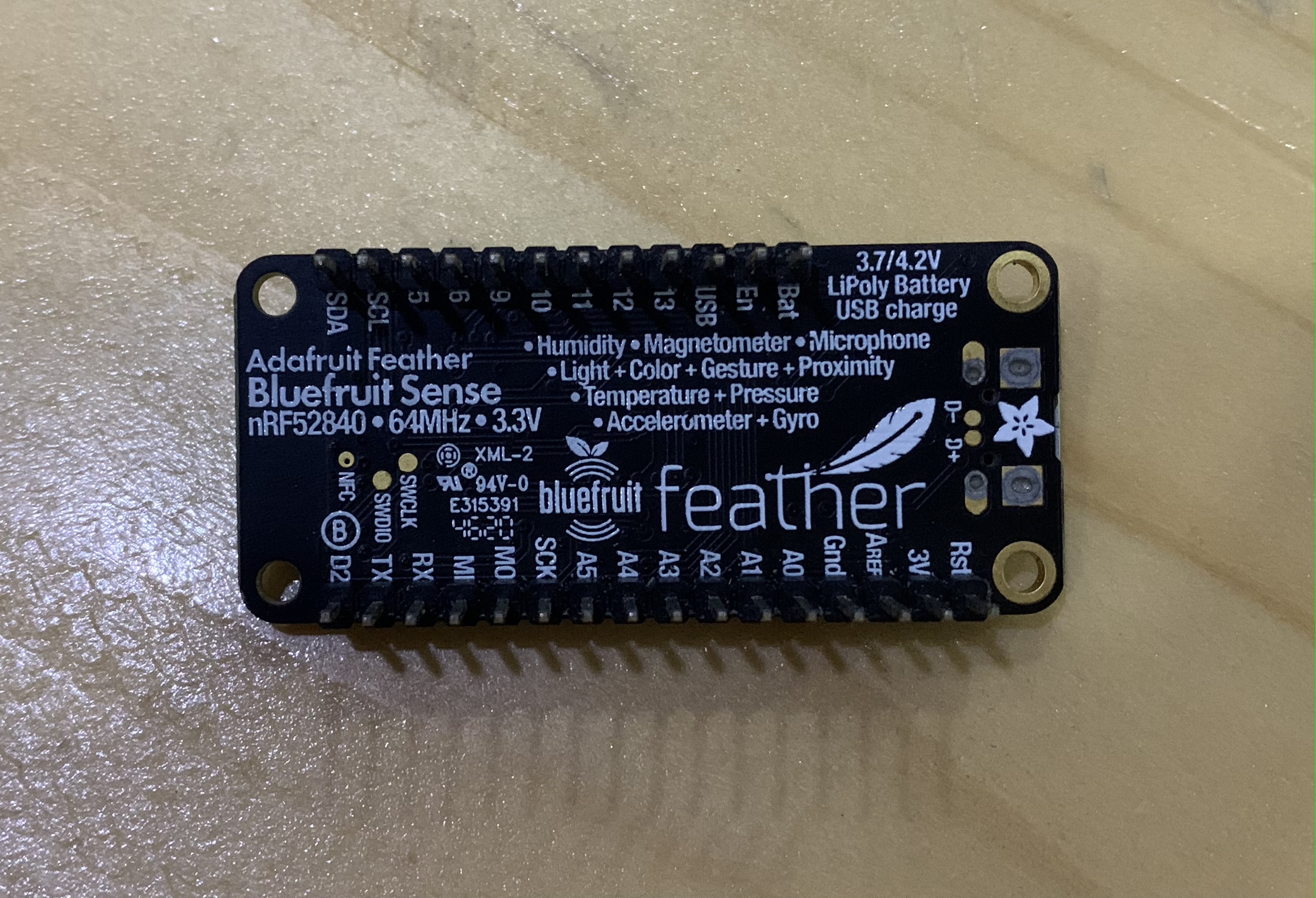
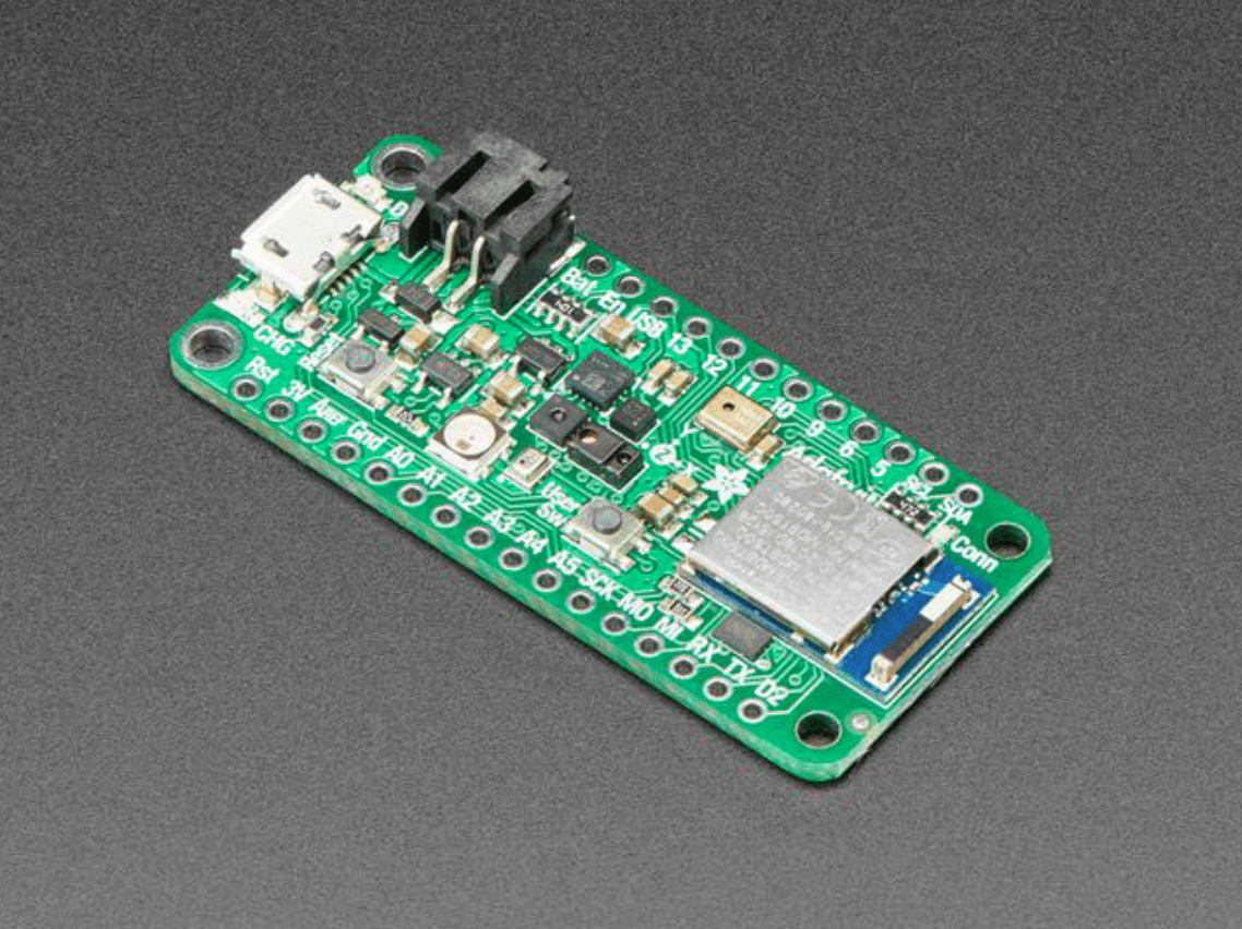
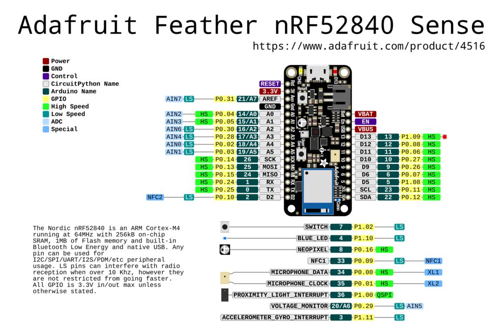
The microcontroller I worked on is Adafruit Feather M0 Bluefruit nRF52840 Sense, this is the datasheet for the microcontroller. This microcontoller has Cortex-M4 chip and it can be programmed by C++, Python, and Arduino programming languages.
PINS
This microcontroller has 28 pins. The pins include; power pins, 6 analog pins (A0 … A5), PWM outputs pin, 12C pins and others.
BUTTONS
This microcontroller has two buttons; reset button and user button. To reset the board quickly press twice on the reset button.
POWER
This microcontroller power could be supplied from USB or from batteries. Connect with a USB cable (just plug into the jack) and the Feather will regulate the 5V USB down to 3.3V. Or connect a 4.2/3.7V Lithium Polymer or Lithium Ion battery to the JST jack. This will let the Feather run on a rechargeable battery.
When the USB power is powered, it will automatically switch over to USB for power, as well as start charging the battery (if attached). This happens ‘hot-swap’ style so you can always keep the LiPoly connected as a ‘backup’ power that will only get used when USB power is lost.
Here batteries can be connected to the BAT pin. And the usb power supply can be connected to USB pin.
SENSORS
This microcontroller has multiple types of sensors including;
- APDS9960 Proximity, Light, Color, and Gesture Sensor ()
- BMP280 Temperature and Barometric Pressure/Altitude ()
- LIS3MDL Magnetometer ()
- LSM6DS33 Accel/Gyro ()
- SHT31 Humidity ()
- PDM Microphone ()
Programming Environments
In a general sense, a programming environment combines hardware and software that allows a developer to build applications. Developers typically work in Integrated Development Environments or IDEs. These connect users with all the features necessary to write and test their code correctly. Using an IDE provides a streamlined development process while minimizing the potential for user error. Four of the most common IDEs are IntelliJ, Eclipse, NetBeans, and Visual Studio. C++ and Python are programming languages. Here will use two programming environemnt; Arduino IDE and Mu Editor. Before programing the microcontroller Arduino IDE and Mu Editor need to be downloaded.
Arduino IDE
The Arduino Integrated Development Environment - or Arduino Software (IDE) - contains a text editor for writing code, a message area, a text console, a toolbar with buttons for common functions and a series of menus. It connects to the Arduino hardware to upload programs and communicate with them.
![]()
1. Step 1, Open this website, and choose your download option.
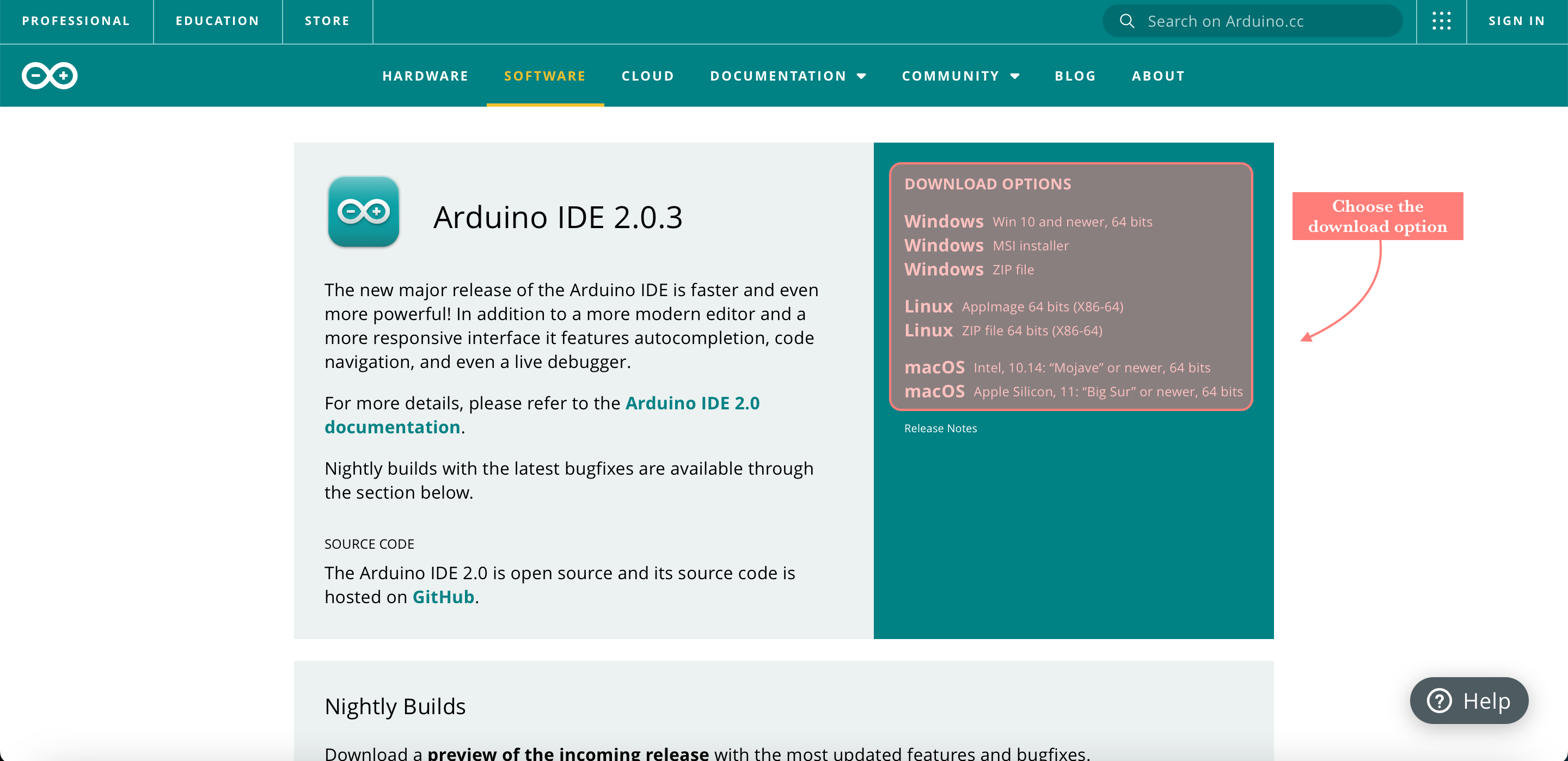
2. Step 2, Then click just download, it does not take long to download.
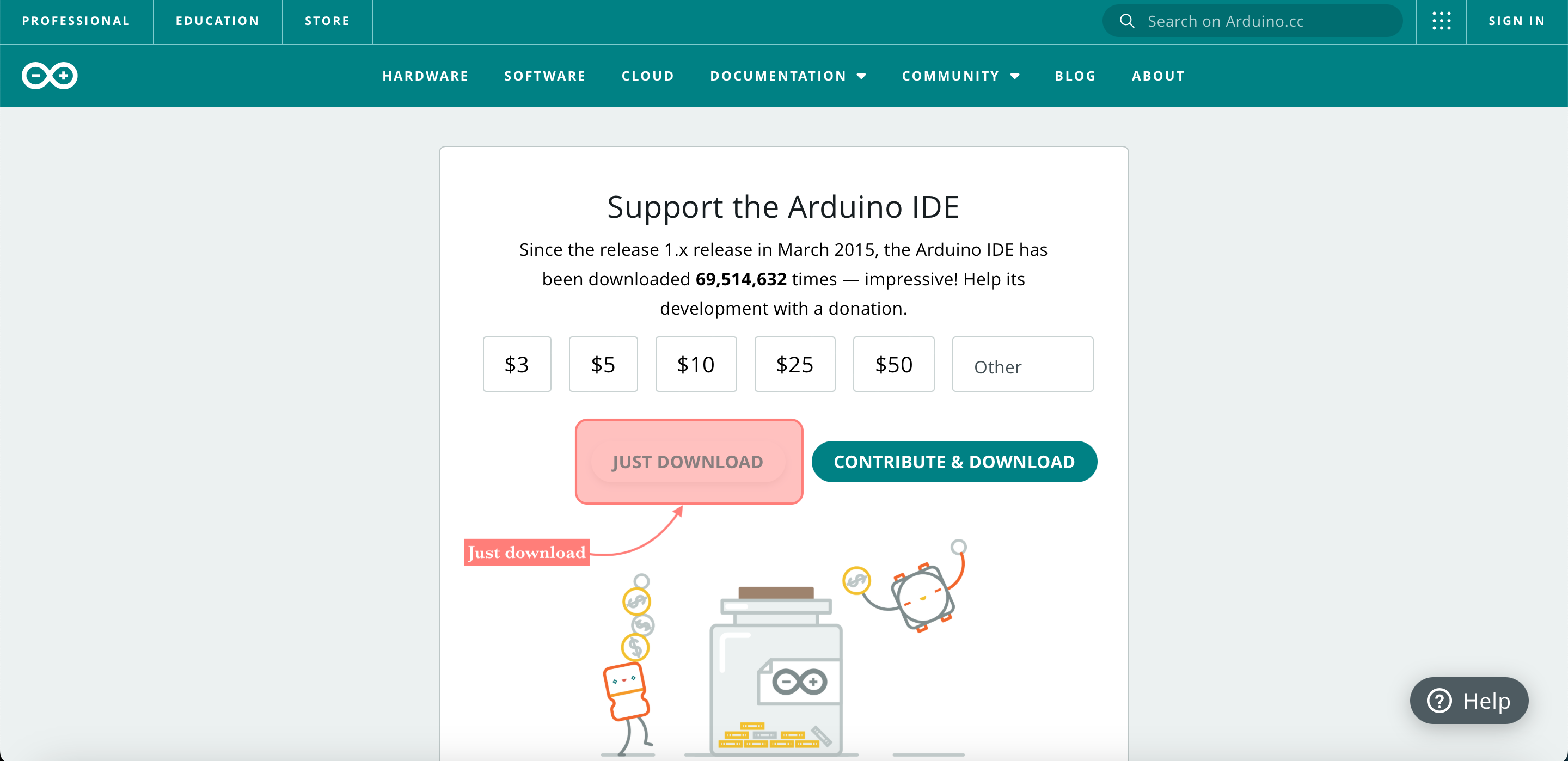
3. Step 3, Then follow the steps of the Board Support Package - BSP Installation from this website, in order to set up the microntroller with the Arduino IDE.
This is the Arduino IDE window
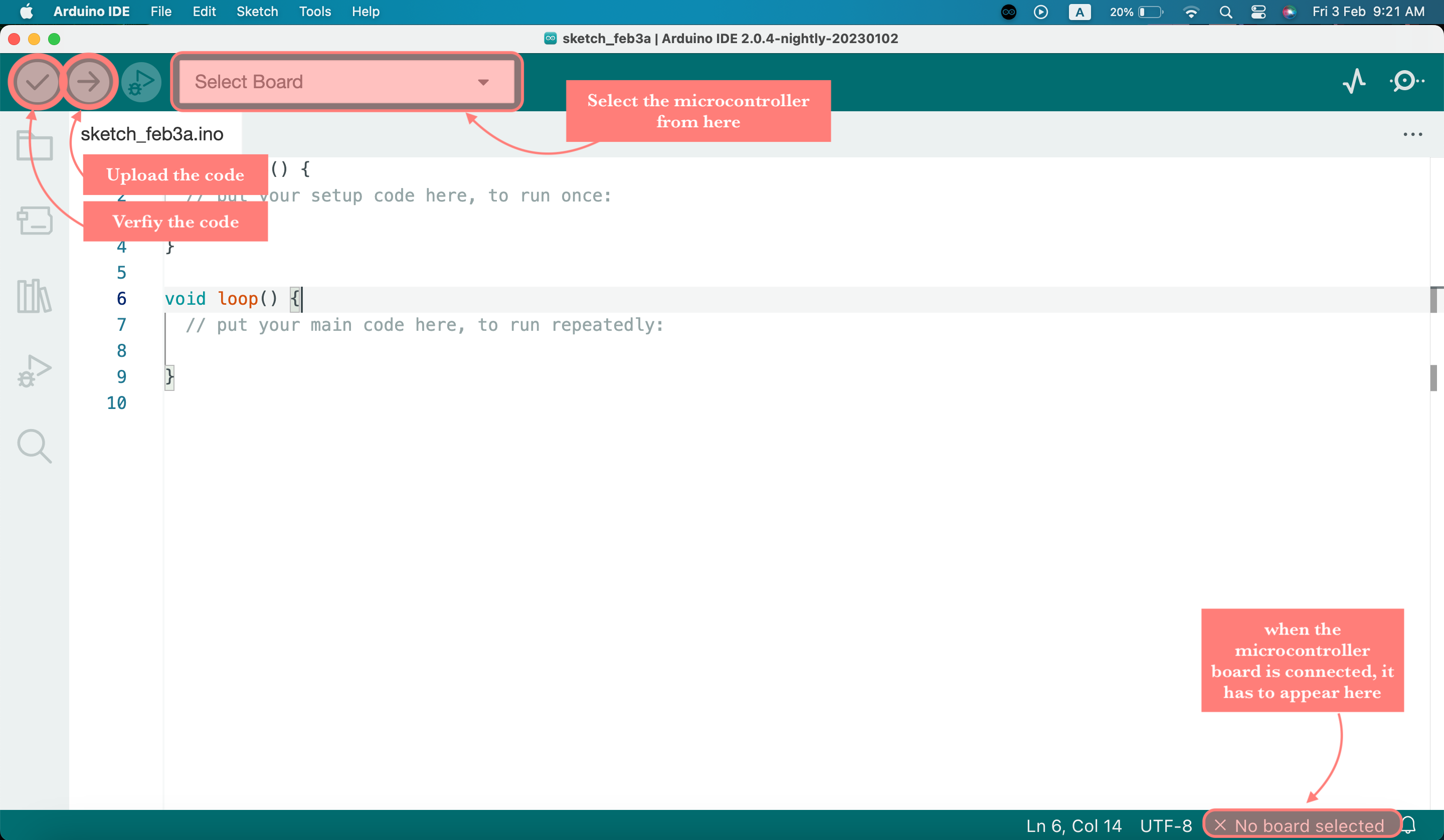
From Tools, you can select the microcontroller board and port

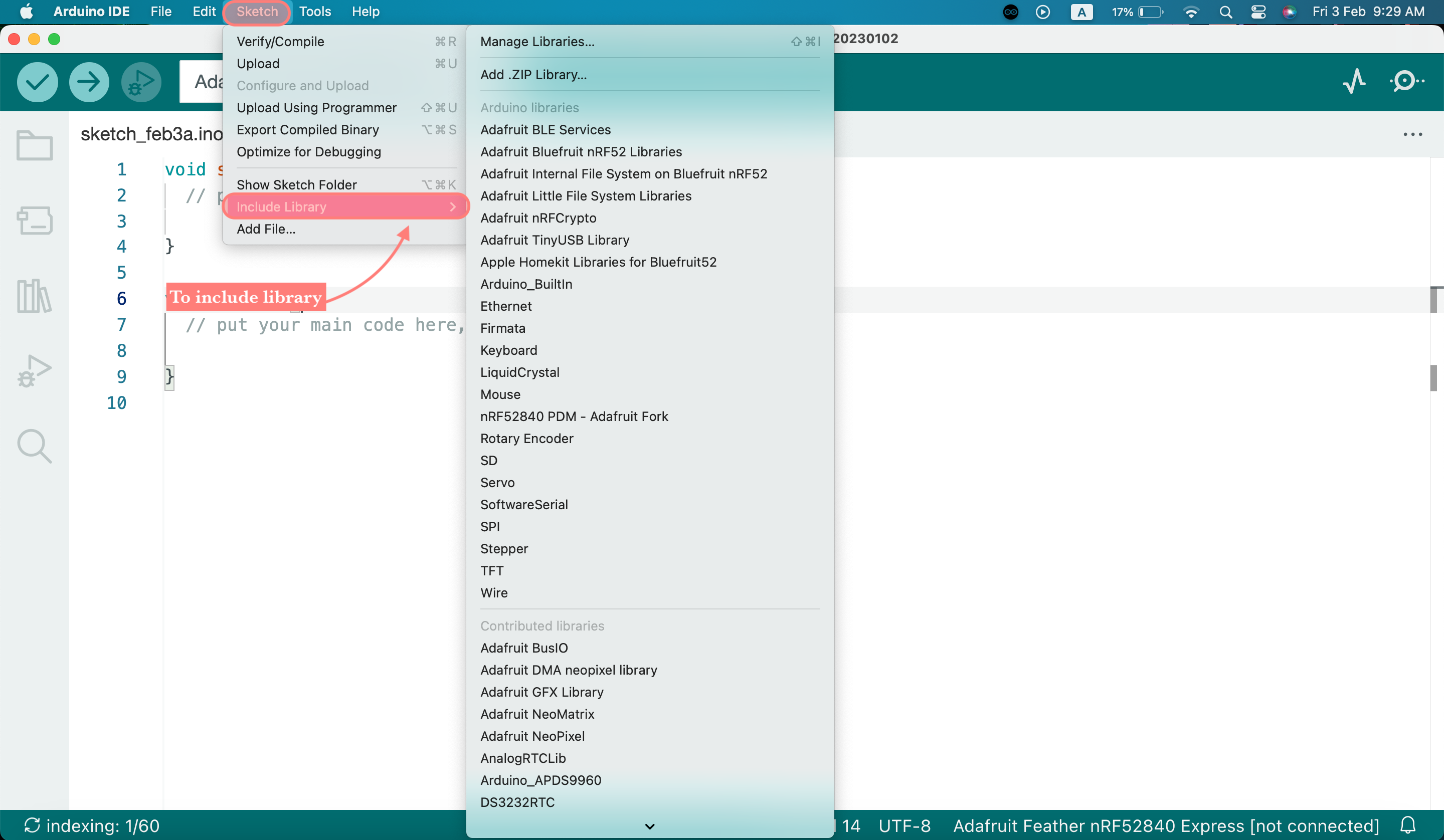
From Sketch you can include the libraies
4. Step 4, After completing this, I can use a USB cord to connect the microntroller to my laptop. By doing this, you should be able to see that the orange LED has begun to flash. It is now powered by its connection to my laptop. And the NeoPixel LED will flash to GREEN when I double-click the RESET switch to reset the microcontroller. However, it will flash RED if there is a problem with this instead.
Since the more recent version 2.0 wasn’t functioning properly for me and wasn’t recognizing the microcontroller, I utilized Arduino IDE version 1.8 on MacOS. It is better to use an older version of an application because they are frequently more stable if it isn’t performing as expected on your device.
Mu Editor
Mu is a very simple to use Python editor and IDE (integrated development environment) for beginners. It’s designed to be as user-friendly and helpful as possible for new Python programmers.

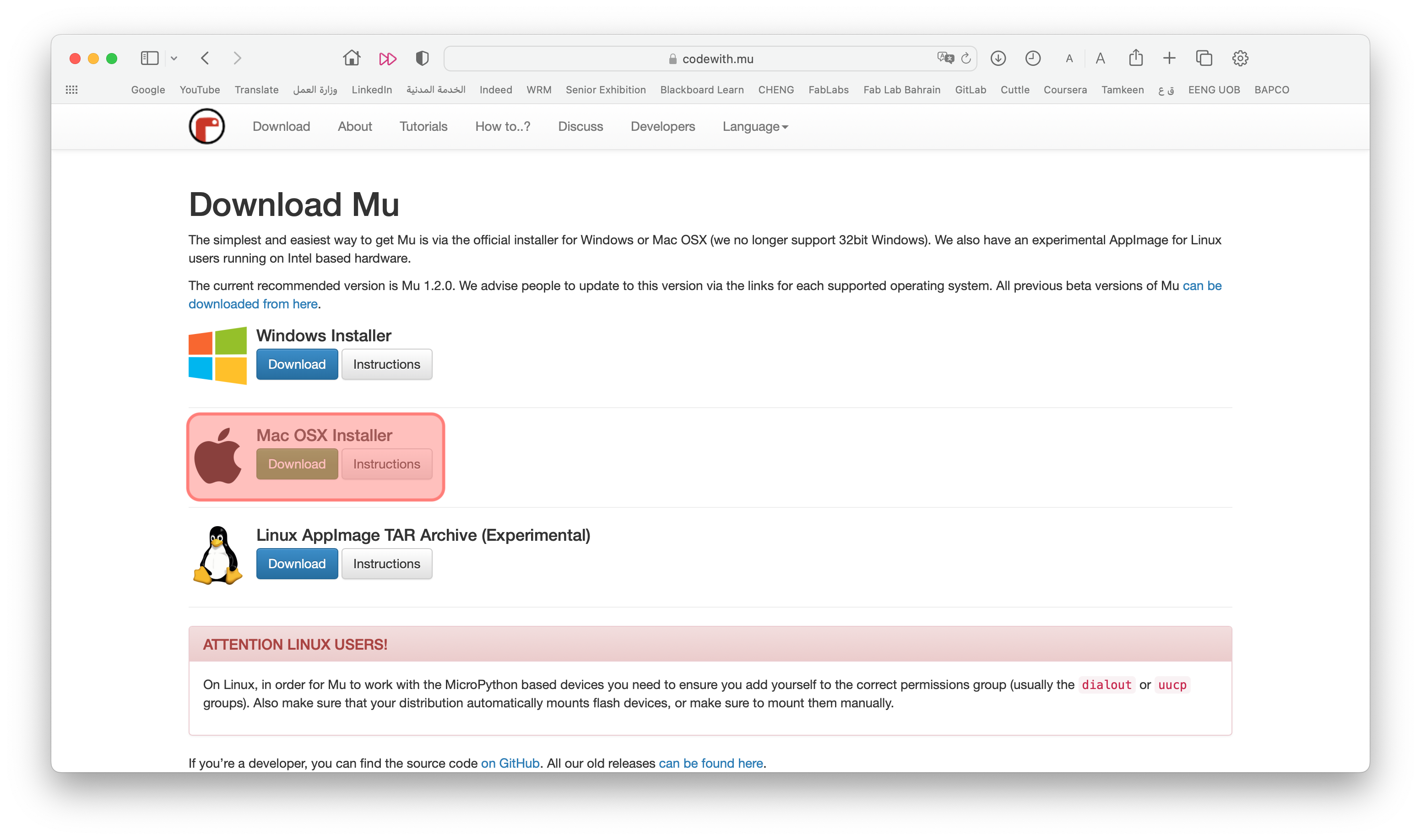
1. Step 1, To download Mu Editor, open this website and click download

2. Step 2, Choose your installer, and it will be downloaded
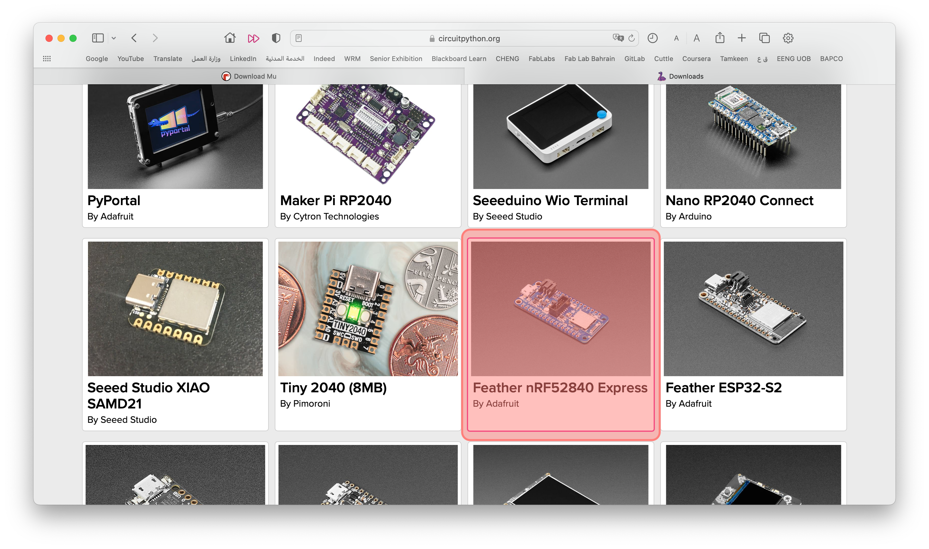
3. Step 3, To download CircuitPython open this website, and choose your microcontoroller
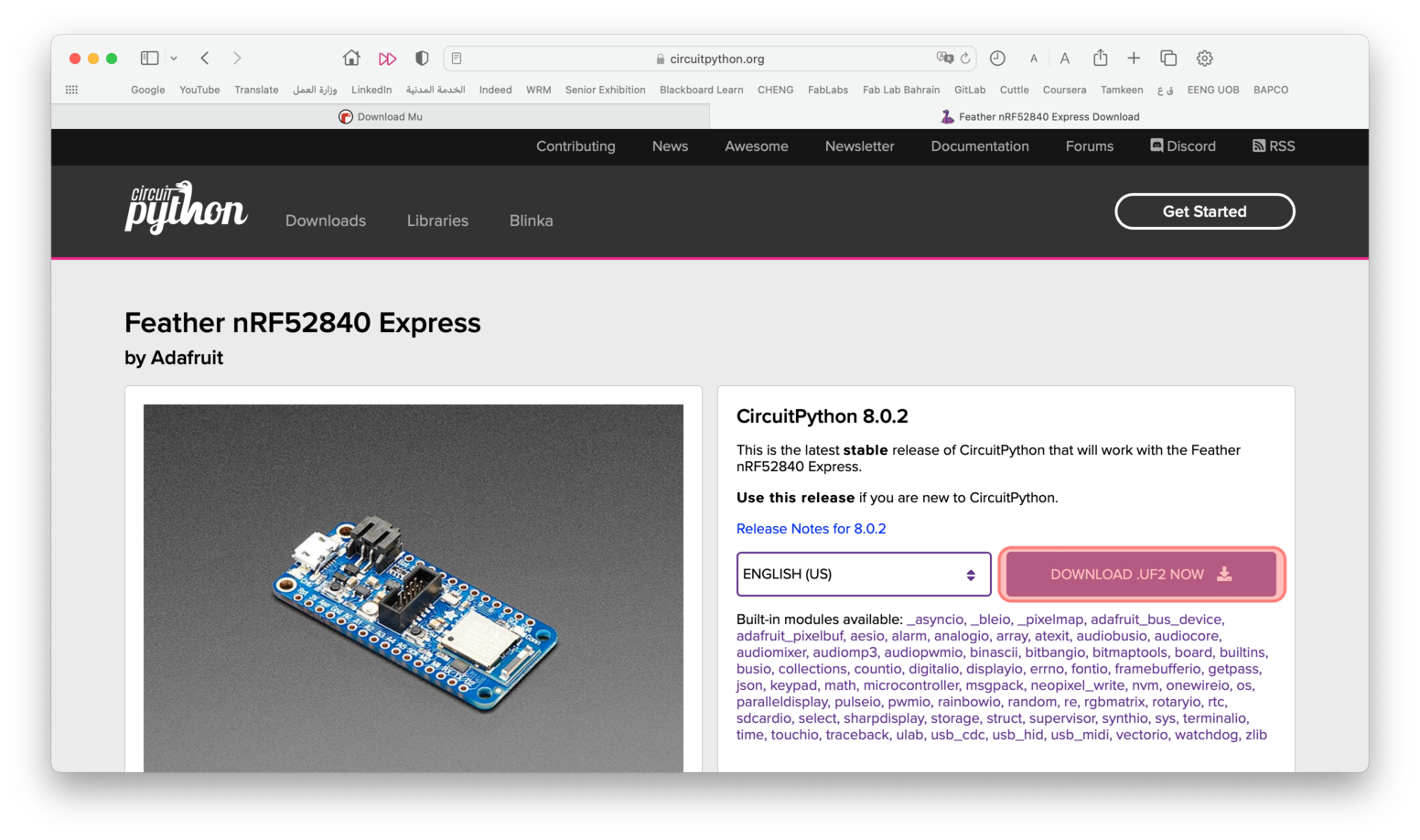
4. Step 4, Click download
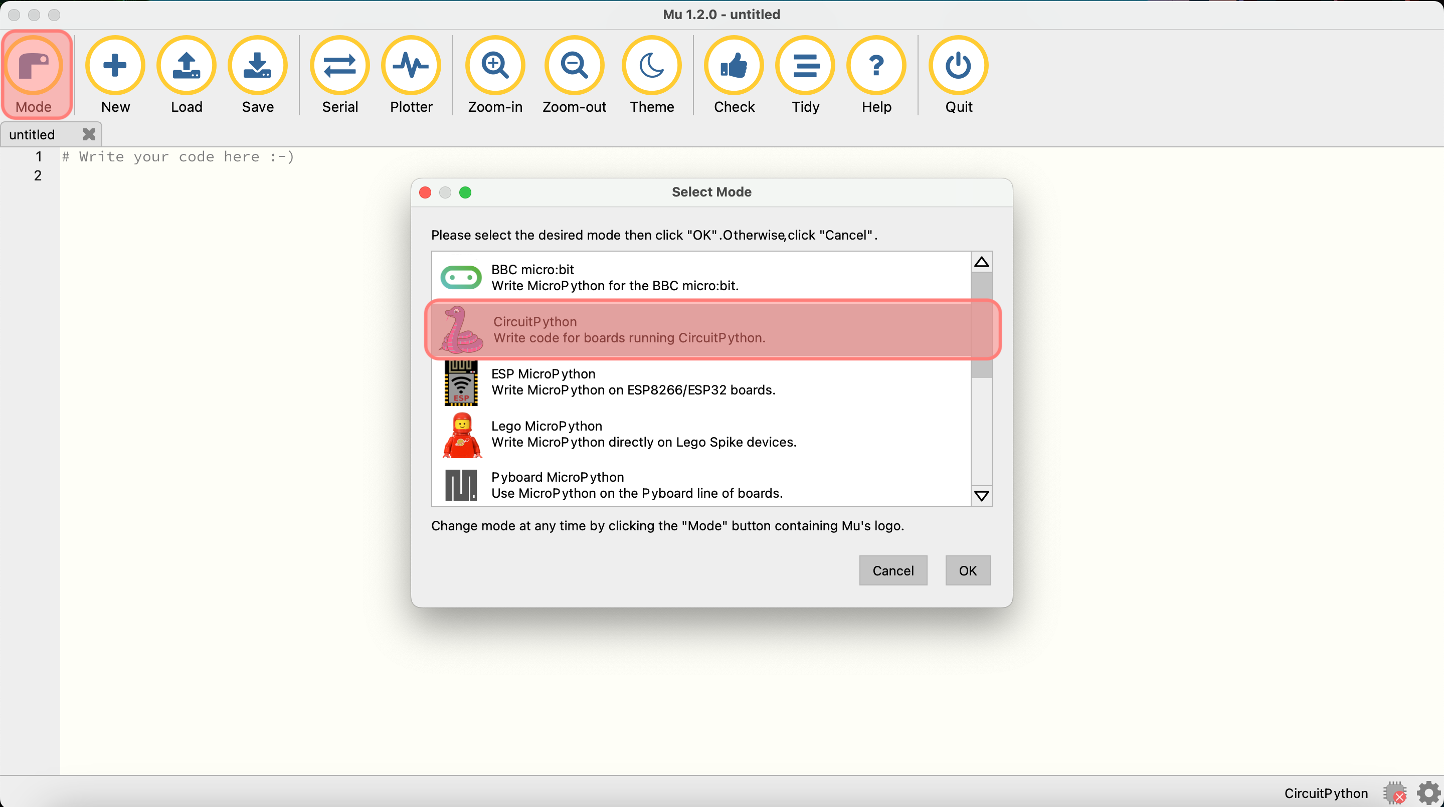
5. Step 5, Open Mu Editor, click mode and choose CircuitPython
6. Step 6, Now copy the CircuitPython file downloaded and paste it in the microcontroller file that pops up when you attach the microcontroller (FTHR840BOOT), by doing this the file name will change to CIRCUITPY
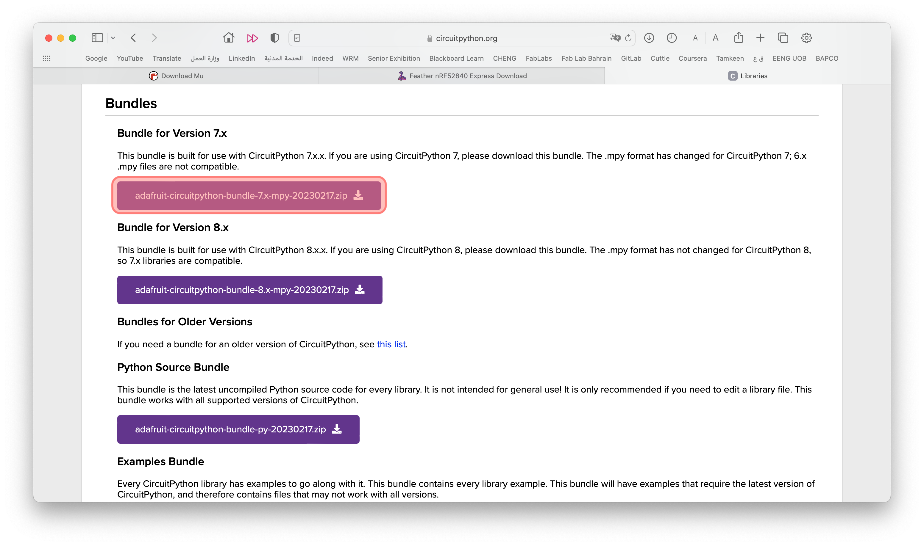
7. Step 7, To download CircuitPython libraries open this website, and dowload Bundle for Version 7.x, move the downloaded file to CIRCUITPY file
Note: When you save any file using Mu Editor it will be saved in the CIRCUITPY folder, to be able to run the code, it must be saved as code.py. So save your files locally on your computer to avoid any problem.
Programming The Microcontroller
We had three challenges to implement with at least two different programming environments.
- Easy Mode Challenge: blink the LED but have the blink delay periods be randomized values between 1 second and 5 seconds.
- Medium Mode Challenge: pre code the microcontroller to send a Morse code of one word message and challenge someone to figure it out.
- Hard Mode Challenge: select the duration of the light being on and off, while the program is running by entering it in the serial monitor. Write a code that takes the data from the serial moniter, and delays by that amount of time. -could not do it!-
Easy Mode Challenge
Easy Mode Challenge: blink the LED but have the blink delay periods be randomized values between 1 second and 5 seconds.
I started this code by using the code I got from Arduino basic blink example, and then changed the dalay time to be random.

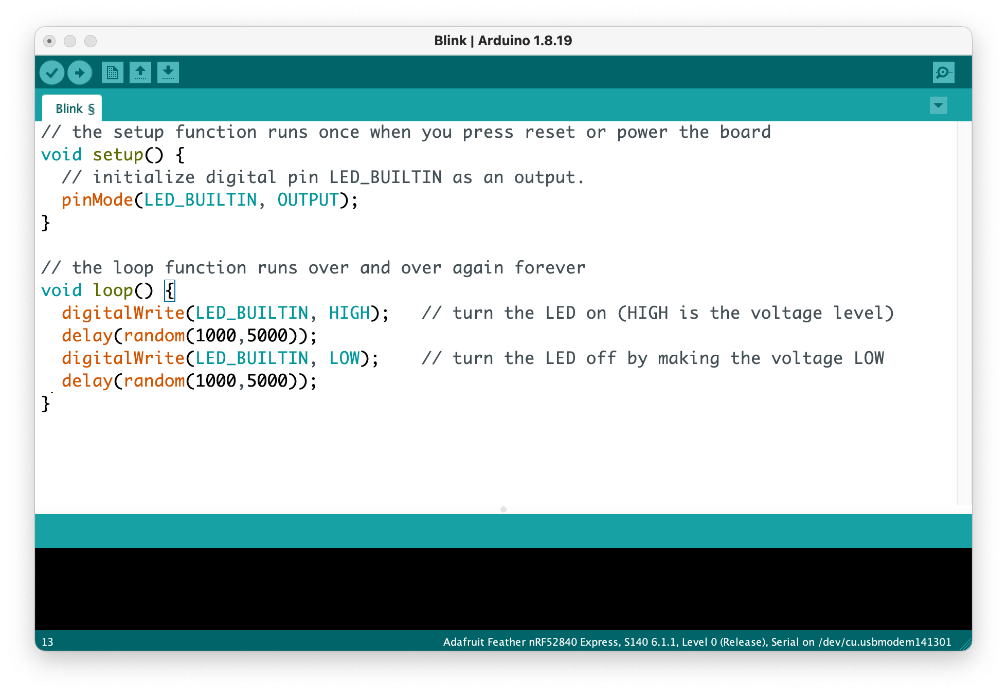
My code using Arduino
// the setup function runs once when you press reset or power the board
void setup() {
  // initialize digital pin LED_BUILTIN as an output.
  pinMode(LED_BUILTIN, OUTPUT);
}

// the loop function runs over and over again forever
void loop() {
  digitalWrite(LED_BUILTIN, HIGH);   // turn the LED on (HIGH is the voltage level)
  delay(random(1000,5000));
  digitalWrite(LED_BUILTIN, LOW);    // turn the LED off by making the voltage LOW
  delay(random(1000,5000));
}
My code using Mu Editor
import board
import time
import digitalio
import random

# using the LED as output
led = digitalio.DigitalInOut(board.LED)
led.direction = digitalio.Direction.OUTPUT

while True:
    led.value = True  # ON
    time.sleep(random.randint(1, 5))
    led.value = False # OFF
    time.sleep(random.randint(1, 5))
This is a video that displays the LED light blinking randomly.
Medium Mode Challenge
Medium Mode Challenge: pre code the microcontroller to send a Morse code of one word message and challenge someone to figure it out. To use Morse code use the following guide tables.
LED Action to Morse Code
| Morse Code | Dot | Dash | Gab Between Dot & Dashes | Gab Between Letters | Gab At The End of a Full Word |
|---|---|---|---|---|---|
| LED Action | 1 second light on | 2 second light on | 0.5 second light off | 3 second light off | 5 second light off |
Alphabet Letters in Morse Code
| Letter | Morse Code | Letter | Morse Code | Letter | Morse Code |
|---|---|---|---|---|---|
| A | . - | J | . - - - | S | . . . |
| B | - . . . | K | - . - | T | - |
| C | - . - . | L | . - . . | U | . . - |
| D | - . . | M | - - | V | . . . - |
| E | . | N | - . | W | . - - |
| F | . . - . | O | - - - | X | - . . - |
| G | - - . | P | . - - . | X | - . . - |
| H | . . . . | Q | - - . - | Z | - - . . |
| I | . . | R | . - . |
I wanted to display the word “Hello”, according to the guide tables above. So this is my code.
My code using Arduino
// the setup function runs once when you press reset or power the board
void setup() {
  // initialize digital pin LED_BUILTIN as an output.
  pinMode(LED_BUILTIN, OUTPUT);
}

// the loop function runs over and over again forever
void loop() {
  //H
  digitalWrite(LED_BUILTIN, HIGH);   // turn the LED on (HIGH is the voltage level)
  delay(1000);                       // wait for a second
  digitalWrite(LED_BUILTIN, LOW);    // turn the LED off by making the voltage LOW
  delay(500);                       // wait for a second
  digitalWrite(LED_BUILTIN, HIGH);   // turn the LED on (HIGH is the voltage level)
  delay(1000);                       // wait for a second
  digitalWrite(LED_BUILTIN, LOW);    // turn the LED off by making the voltage LOW
  delay(500);                       // wait for a second
  digitalWrite(LED_BUILTIN, HIGH);   // turn the LED on (HIGH is the voltage level)
  delay(1000);                       // wait for a second
   digitalWrite(LED_BUILTIN, LOW);    // turn the LED off by making the voltage LOW
  delay(500);                       // wait for a second
  digitalWrite(LED_BUILTIN, HIGH);   // turn the LED on (HIGH is the voltage level)
  delay(1000);                       // wait for a second
  digitalWrite(LED_BUILTIN, LOW);    // turn the LED off by making the voltage LOW
  delay(500);                       // wait for a second

  digitalWrite(LED_BUILTIN, LOW);    // turn the LED off by making the voltage LOW
  delay(3000);                       // wait for a second

  //E
  digitalWrite(LED_BUILTIN, HIGH);   // turn the LED on (HIGH is the voltage level)
  delay(1000);                       // wait for a second

  digitalWrite(LED_BUILTIN, LOW);    // turn the LED off by making the voltage LOW
  delay(3000);

  //L
  digitalWrite(LED_BUILTIN, HIGH);   // turn the LED on (HIGH is the voltage level)
  delay(1000);                       // wait for a second
  digitalWrite(LED_BUILTIN, LOW);    // turn the LED off by making the voltage LOW
  delay(500);
   digitalWrite(LED_BUILTIN, HIGH);   // turn the LED on (HIGH is the voltage level)
  delay(2000);                       // wait for a second
  digitalWrite(LED_BUILTIN, LOW);    // turn the LED off by making the voltage LOW
  delay(500);
   digitalWrite(LED_BUILTIN, HIGH);   // turn the LED on (HIGH is the voltage level)
  delay(1000);                       // wait for a second
  digitalWrite(LED_BUILTIN, LOW);    // turn the LED off by making the voltage LOW
  delay(500);
   digitalWrite(LED_BUILTIN, HIGH);   // turn the LED on (HIGH is the voltage level)
  delay(1000);                       // wait for a second
  digitalWrite(LED_BUILTIN, LOW);    // turn the LED off by making the voltage LOW
  delay(500);

  digitalWrite(LED_BUILTIN, LOW);    // turn the LED off by making the voltage LOW
  delay(3000);

  //O
  digitalWrite(LED_BUILTIN, HIGH);   // turn the LED on (HIGH is the voltage level)
  delay(2000);                       // wait for a second
  digitalWrite(LED_BUILTIN, LOW);    // turn the LED off by making the voltage LOW
  delay(500);
   digitalWrite(LED_BUILTIN, HIGH);   // turn the LED on (HIGH is the voltage level)
  delay(2000);                       // wait for a second
  digitalWrite(LED_BUILTIN, LOW);    // turn the LED off by making the voltage LOW
  delay(500);
   digitalWrite(LED_BUILTIN, HIGH);   // turn the LED on (HIGH is the voltage level)
  delay(2000);                       // wait for a second
  digitalWrite(LED_BUILTIN, LOW);    // turn the LED off by making the voltage LOW
  delay(500);

  digitalWrite(LED_BUILTIN, LOW);    // turn the LED off by making the voltage LOW
  delay(5000);
}
This is a video showing the LED blinking on the mircocontoller spelling the word “Hello”
Problems Faced
For some resone my laptop does not opreate well with microcontrollers. The port connecting the microcontroller to the laptop kept disconnecting. So instead of using Arduino IDE, I downloaded the older version of Arduino. However the problem remained. When I changed the microcontroller it worked 🙂, for some time 🙃 and then the same problem kept reappearing. So to solve the problem I used another laptop 💻. After a while the problem is solved.