Final Project 🕰️
During the last 2 weeks I worked on my final project. My final project is a digital clock 🕰️✨. This page include the following:
Part1: The Electronics & Programming
Part2: The Design
The Final Result
Summary
Coming Up With The Idea
During the last 2 weeks we had the opportunity to make anything we want 💡✨ to demonstrate synthesis of skills we developed in the previous weeks, which include 2D and 3D design, additive and subtractive fabrication processes, microcontroller programming and use of input & output devices, and system integration and packaging.
“Early is on time, on time is late, and late is unacceptable!” - Eric Jerome Dickey
Time is the most precious commodity anyone has. It cannot be earned, bought, or regained once it has passed. Therefore, it is important to use it wisely and get the most out of it. Managing and organising time is very important to me and my love 🤍 of bullet journaling and my high level of organization both help me manage my time really well.
Therefore my project idea is to make a clock 🕰️✨, a digital display clock, that is minimal in style, with a wood finish. You can see my inital mood board by clicking here.
Part1: The Electronics & Programming
Testing Soldering Circuit Digram Connection The Code
Testing
continuing from week 8 assignment, input and output devices I used the same set up on a previous Fab Lab project that uses LED strip lights on a grid.
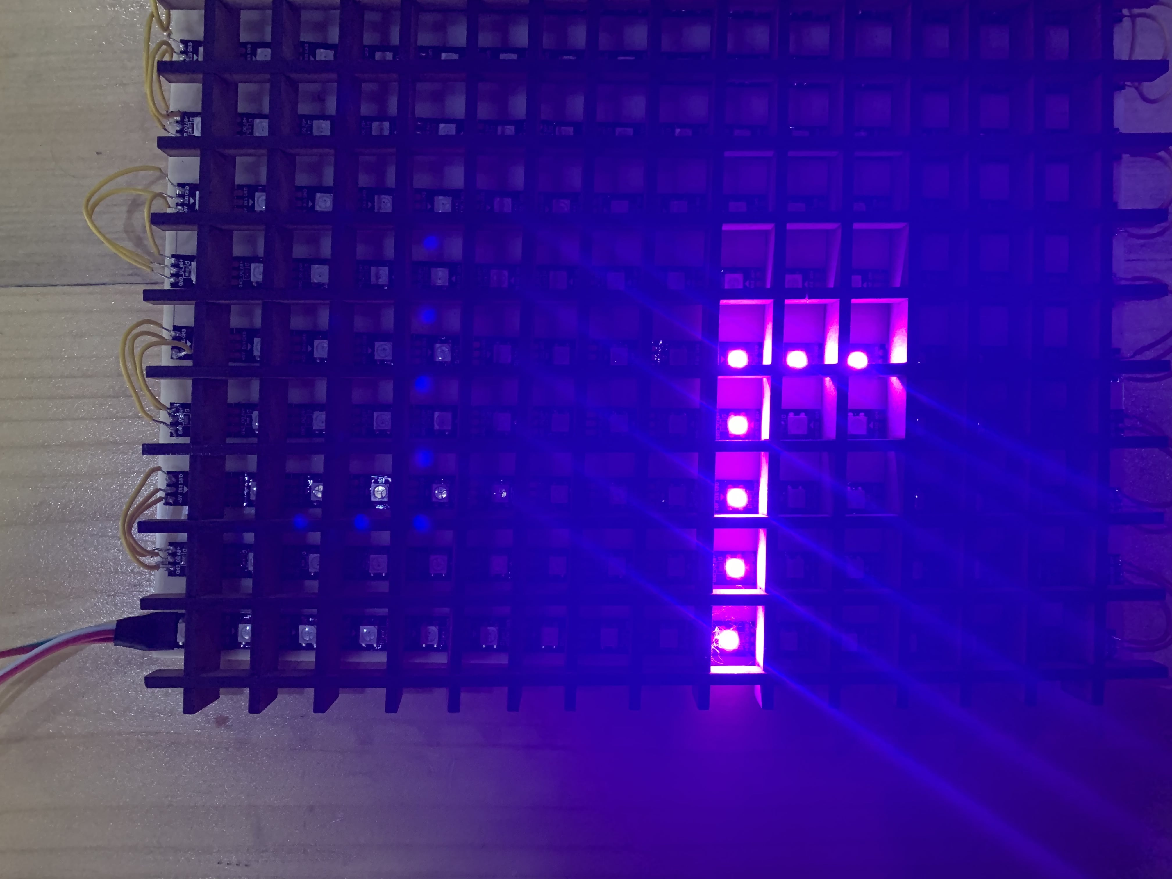
My goal here was to display 07:30, here is a run down of the progress.
This is the first try where the 7 is fliped
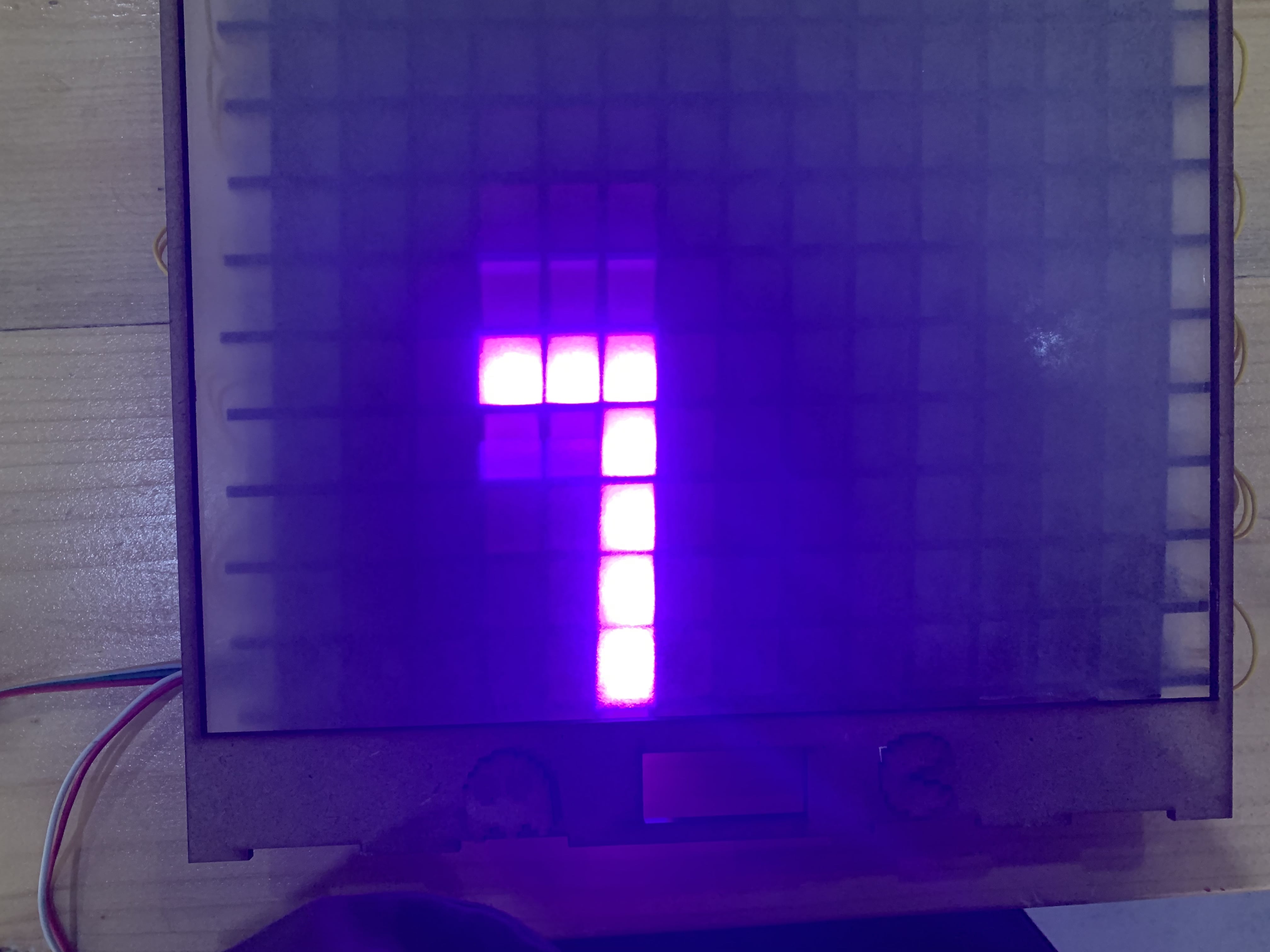
I fixed the 7 here

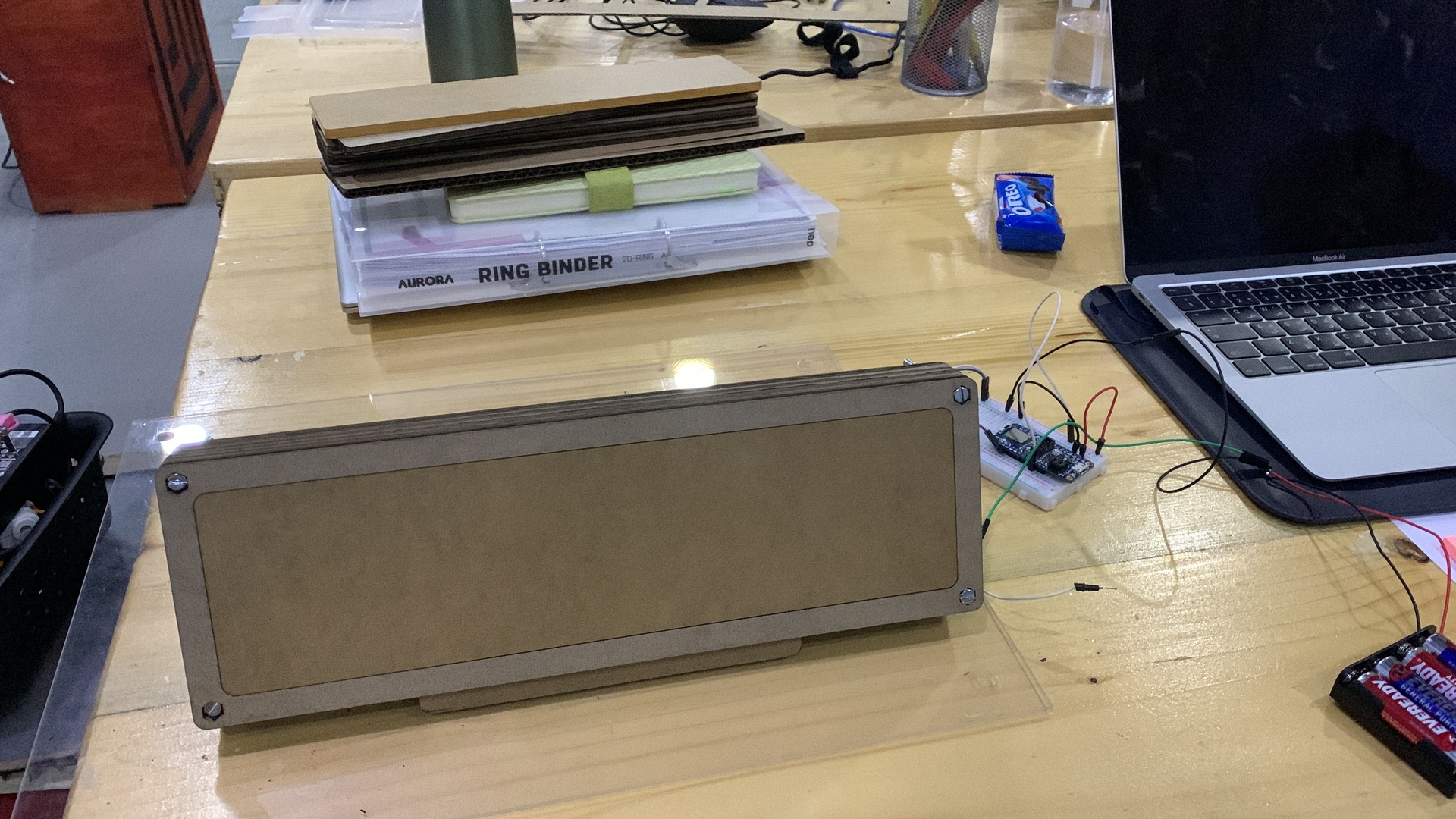
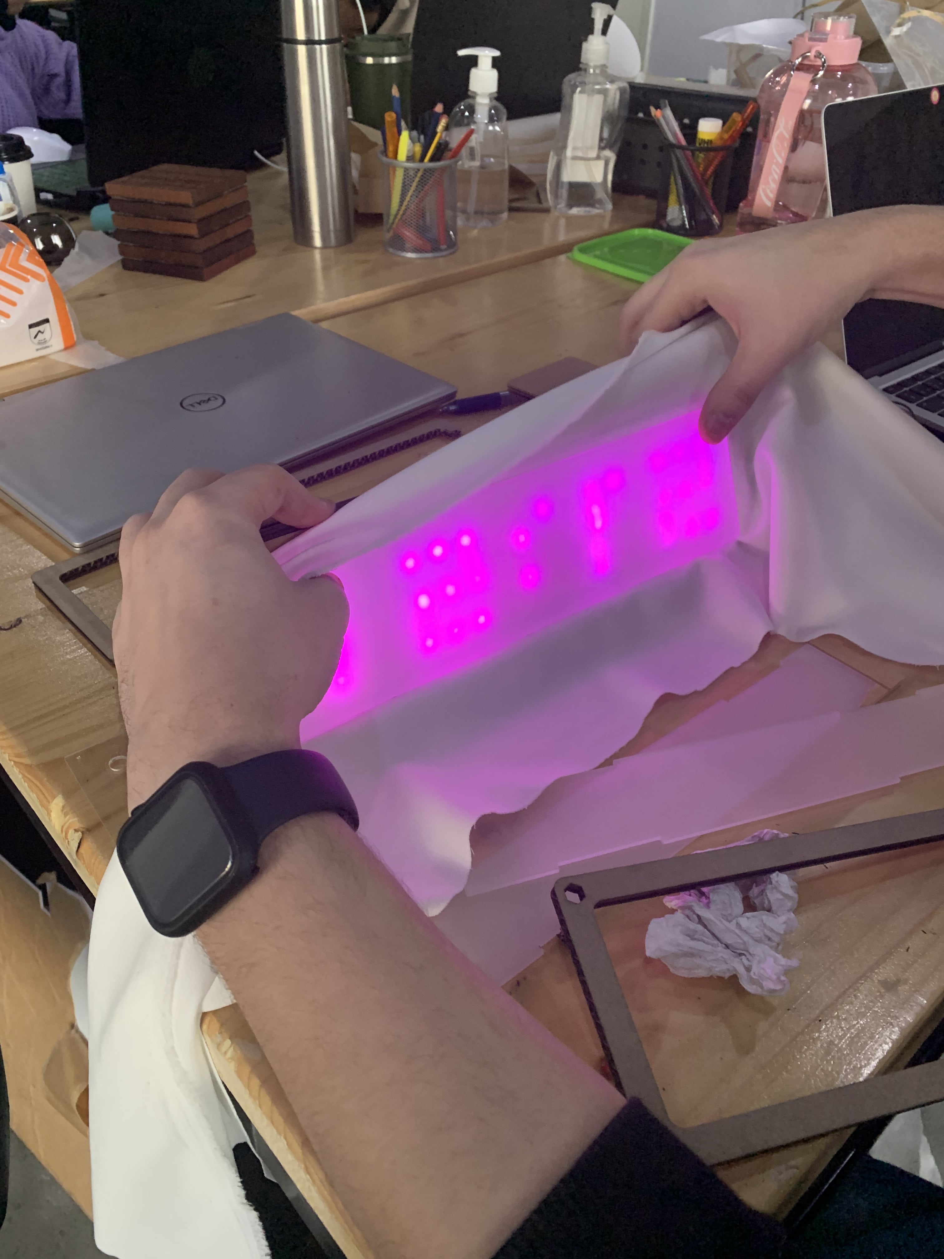
Here you can see it with the sanded acrylic on top to diffuse the light
Then I wanted to display the 0, you can see it here without the diffuser layer
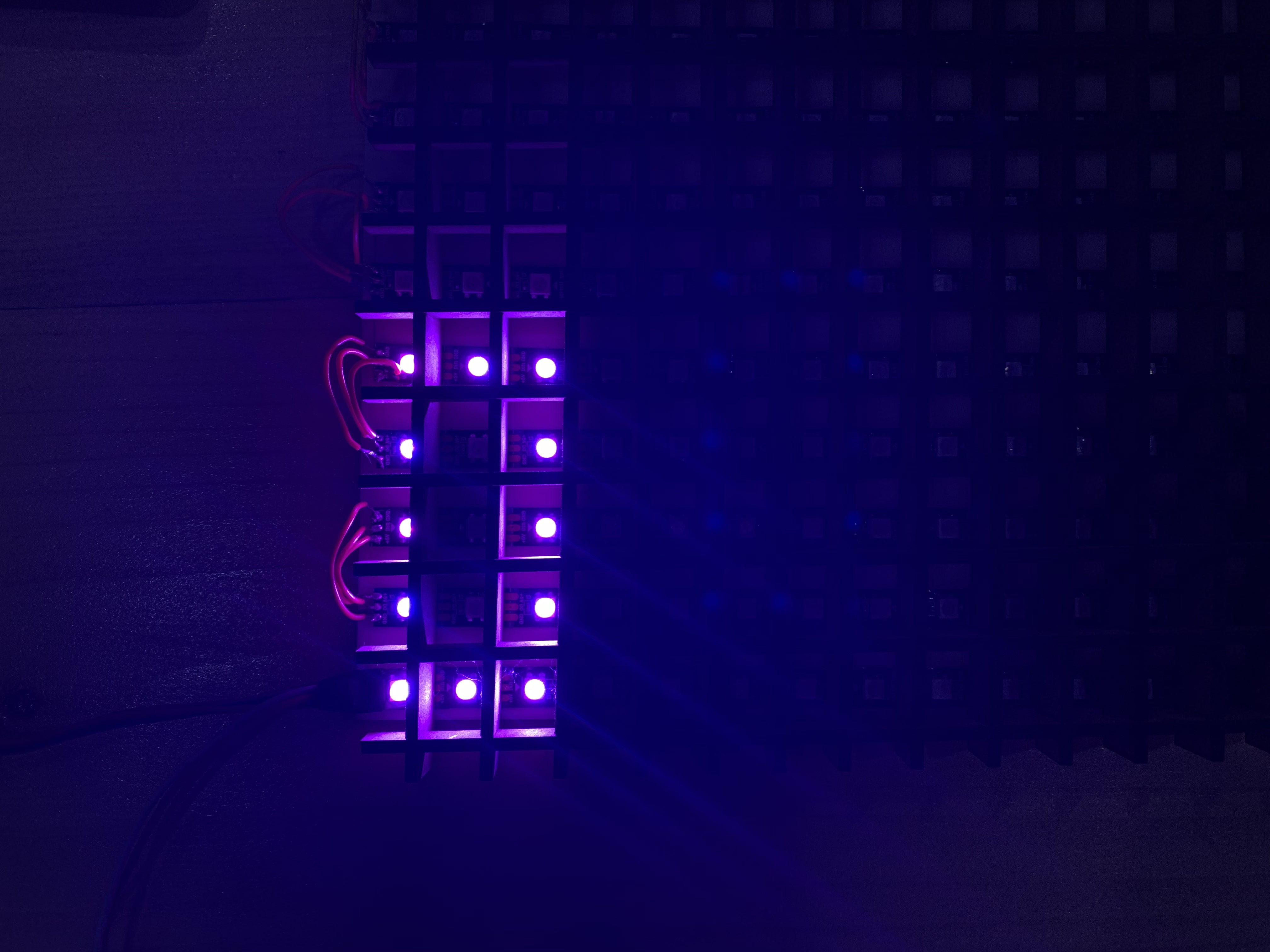
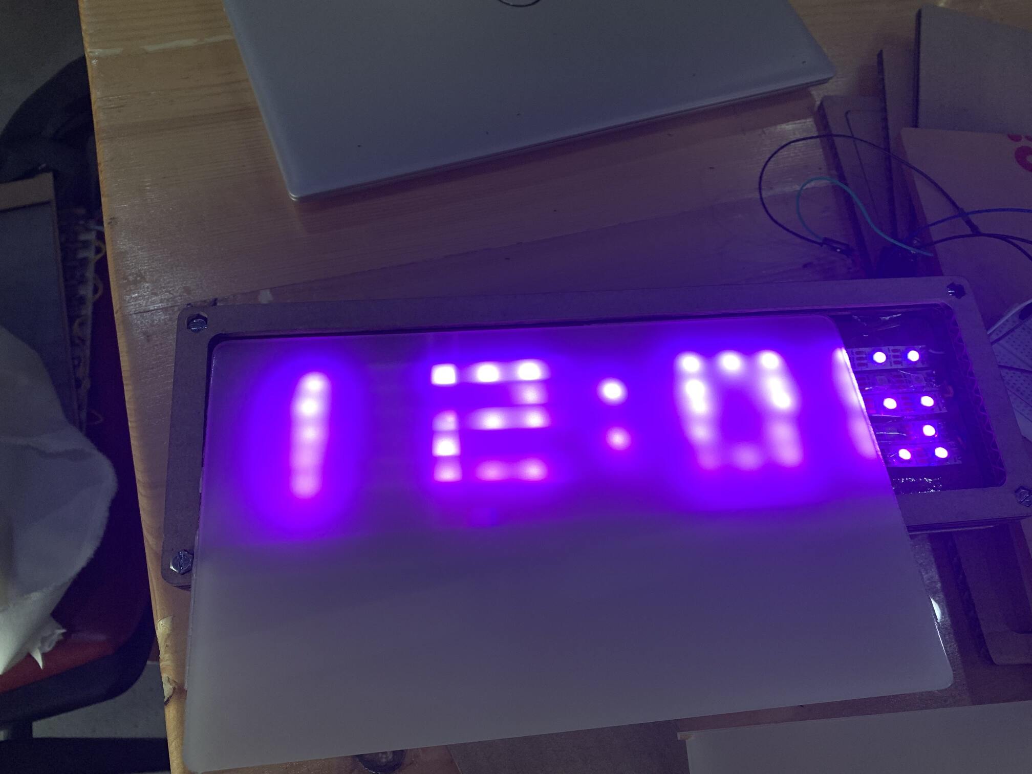
This is the 0 with the diffuser layer

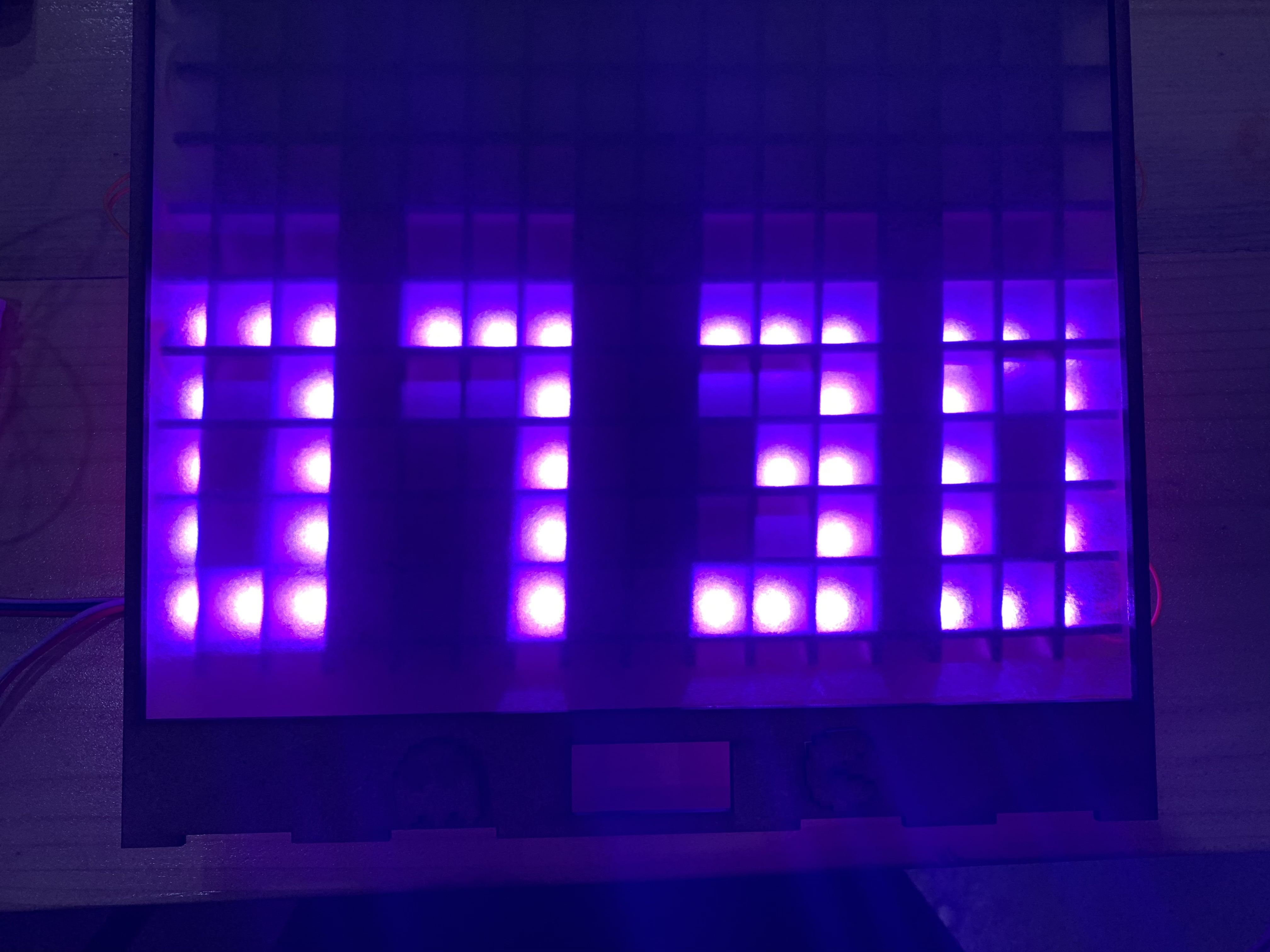
Now I displayed 0 and 7 togather

Here I reached my goal and diplayed 07:30
This was my setup while working

Soldering
After testing on a previous project, I made my own LED strip light grid, and tried soldering for the first time.
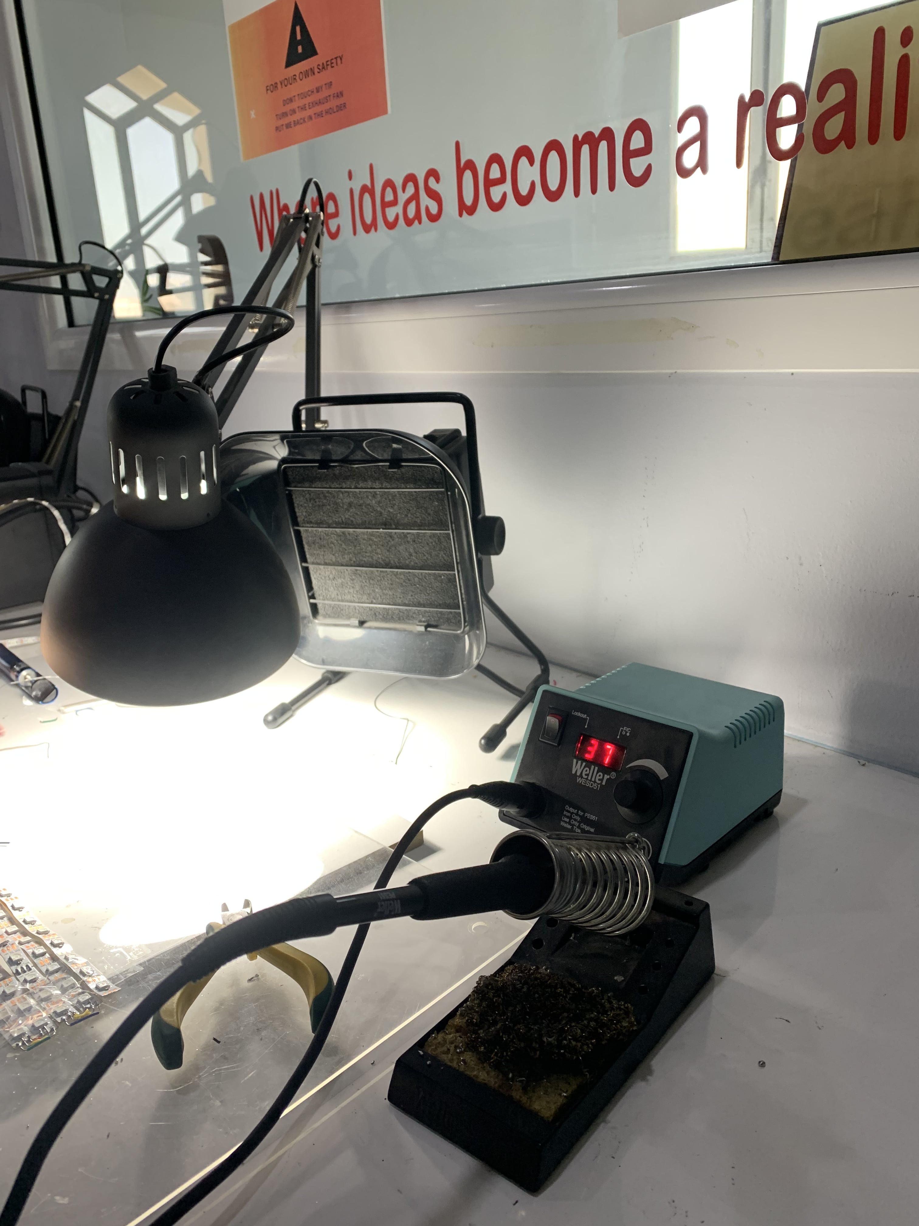
This is the soldering station
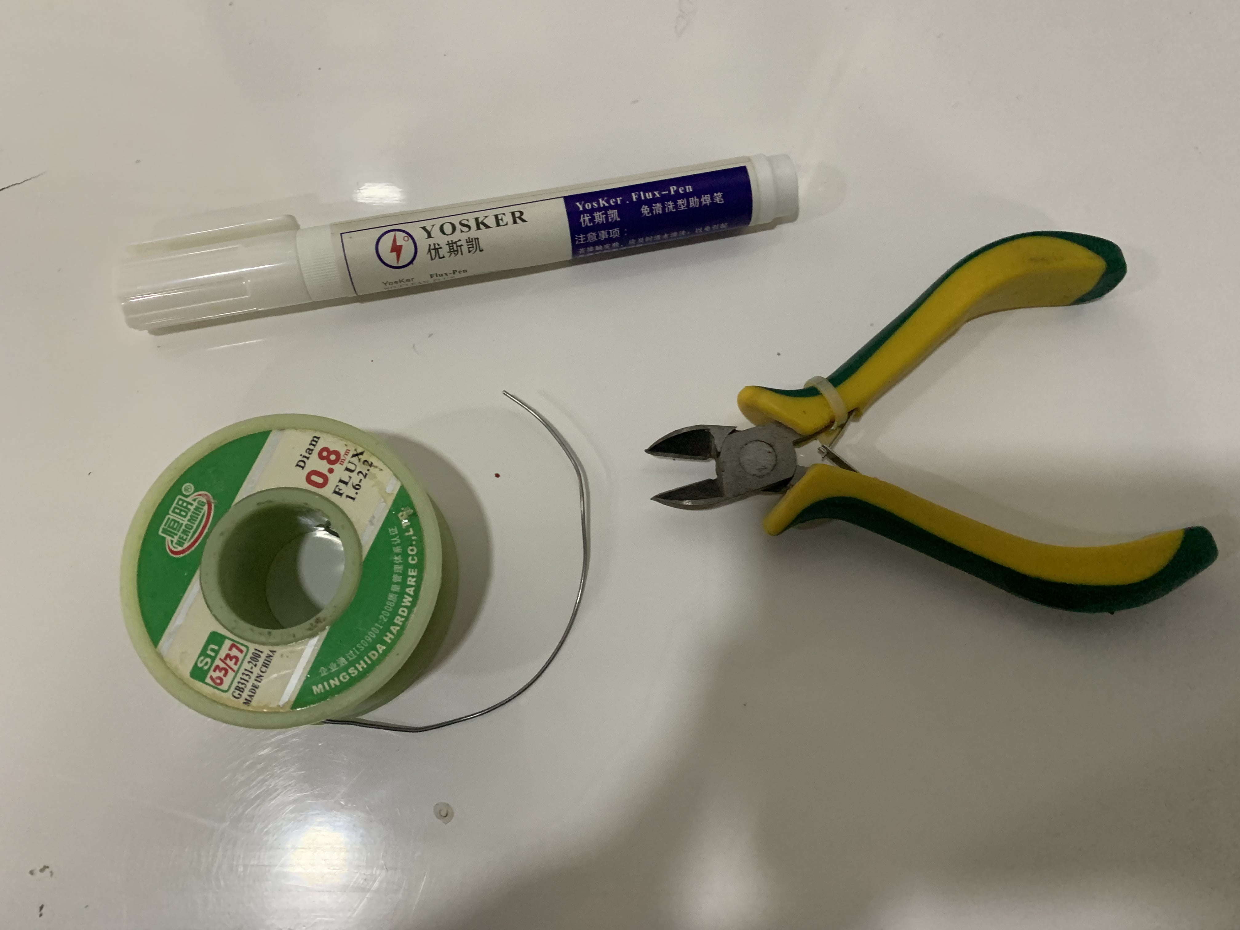
We used a flux pen, a flux pen is a must have when performing any kind of solder rework. The flux is the substance that prevents beading of the solder and helps the solder flow cleanly onto the parts you are soldering. I used 0.8 mm flux solder
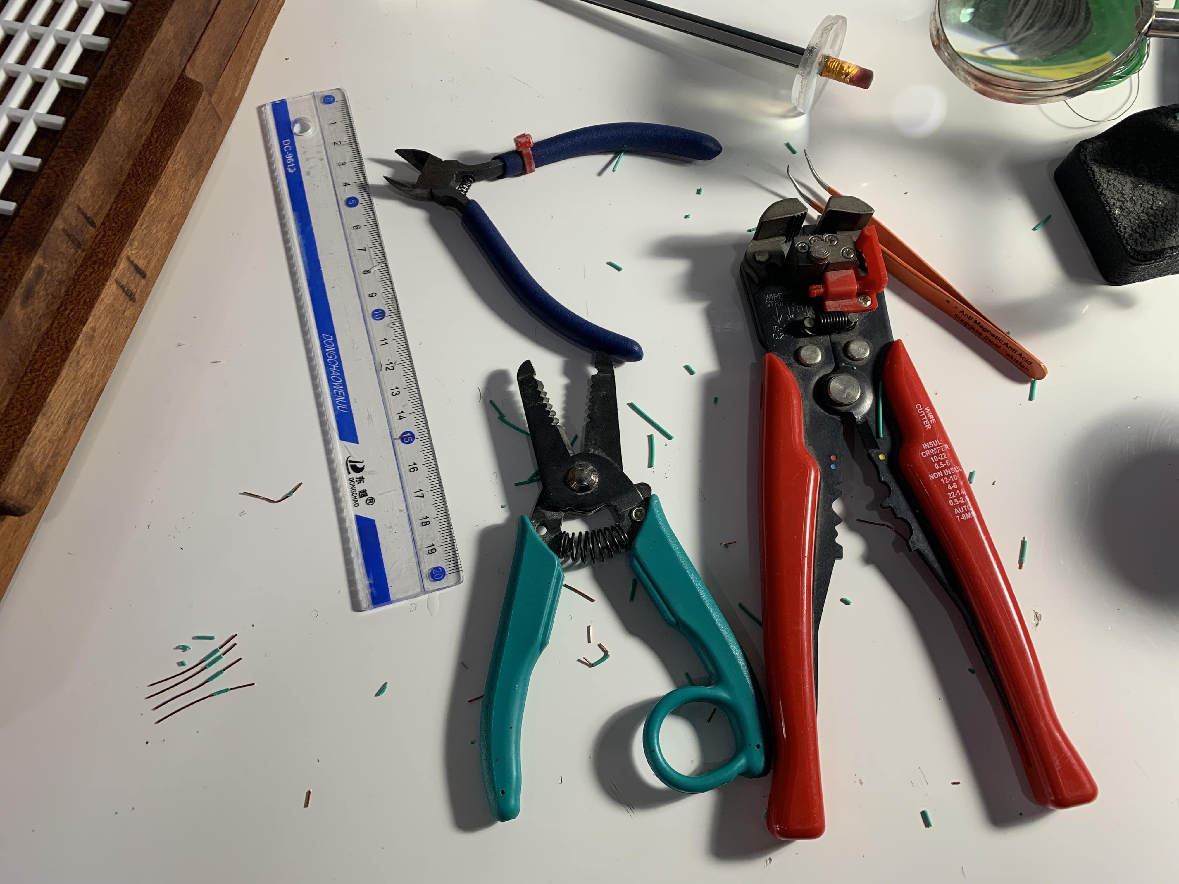
To cut the wires to make the connections I used a cutting plier to cut the wires, wire stripper to strip the wires, and a ruler to measure the length of the wires. I used the less flexible wires.
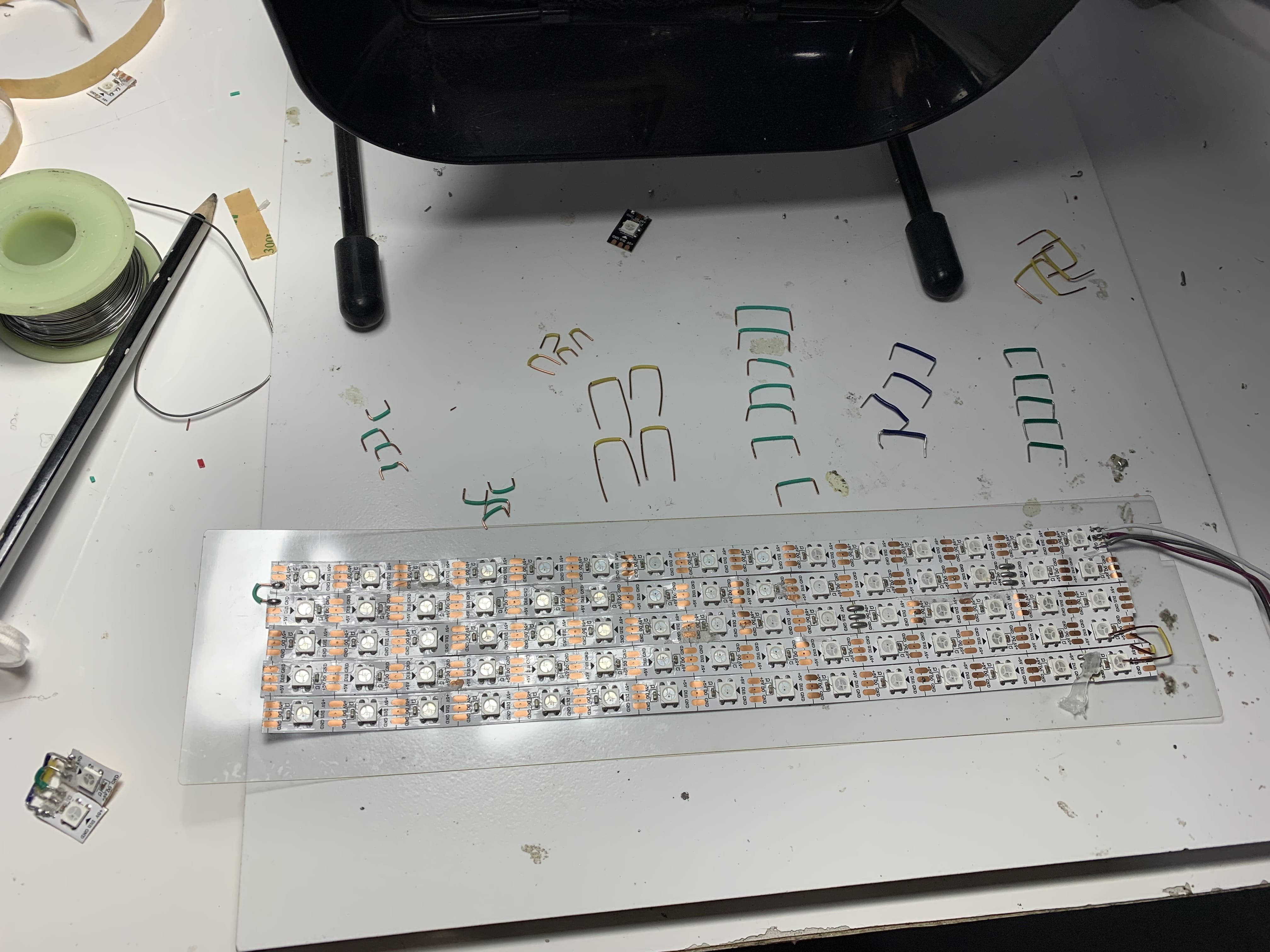
Here you can see the cut wires prepared.
Note: I used 5 LED strip lights each has 15 lights, the direaction on the LED strip lights is important
This is how the soldering turned out
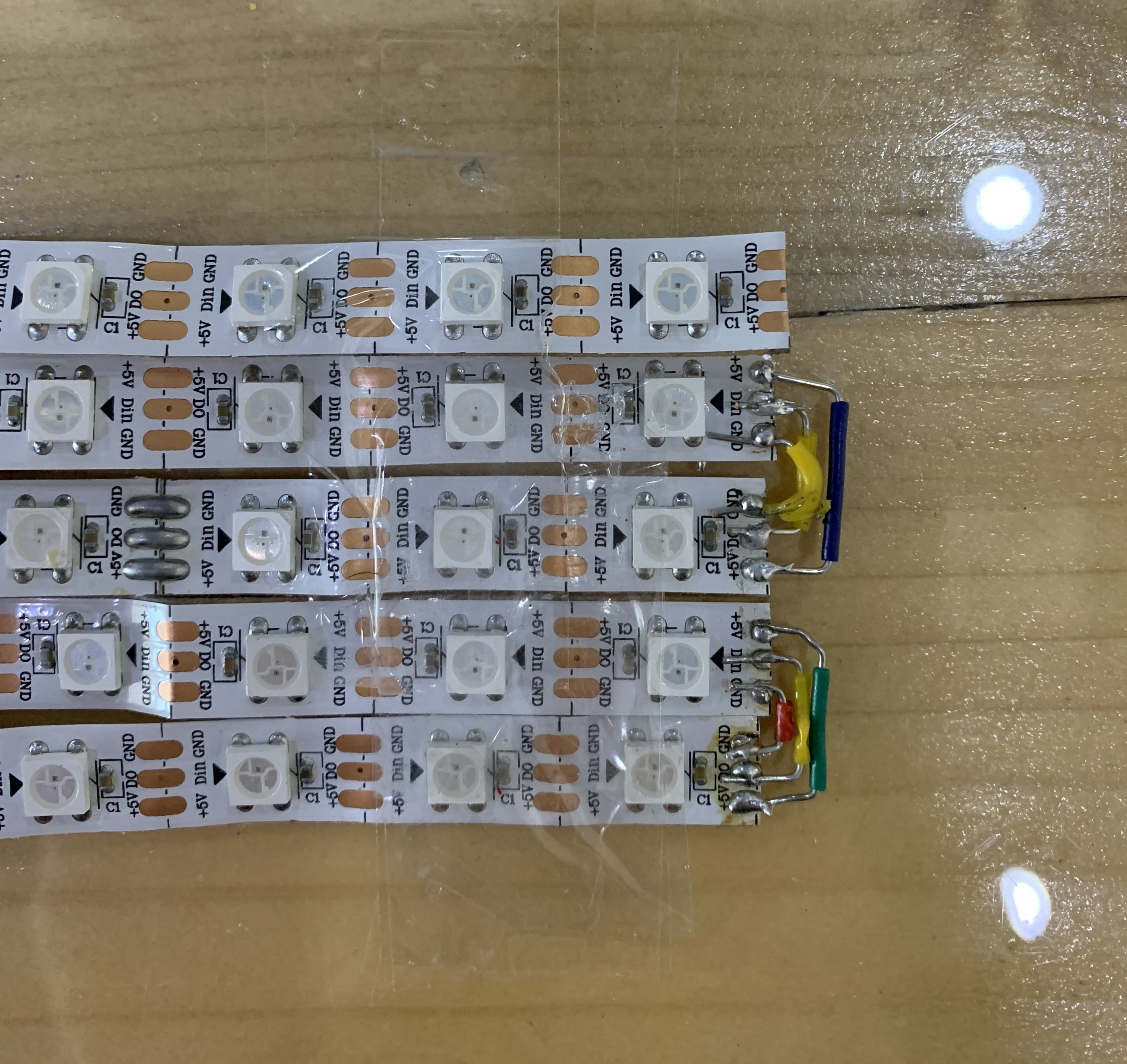
The soldered LED lights connected

Circuit Digram Connections
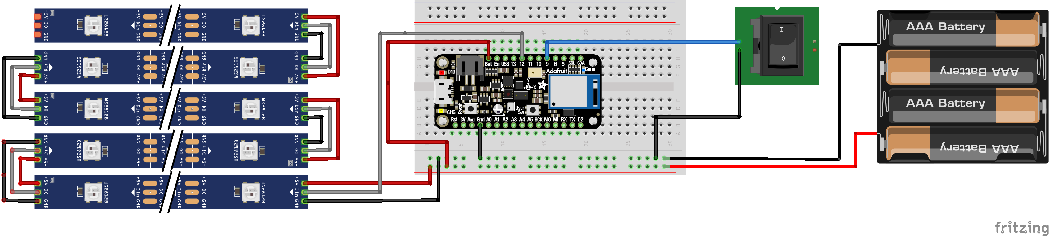
There are four main components:
- Adafruit Feather M0 Bluefruit nRF52840 Express Microcontroller
- LED Strip Lights
- On and Off Switch
- Batteries
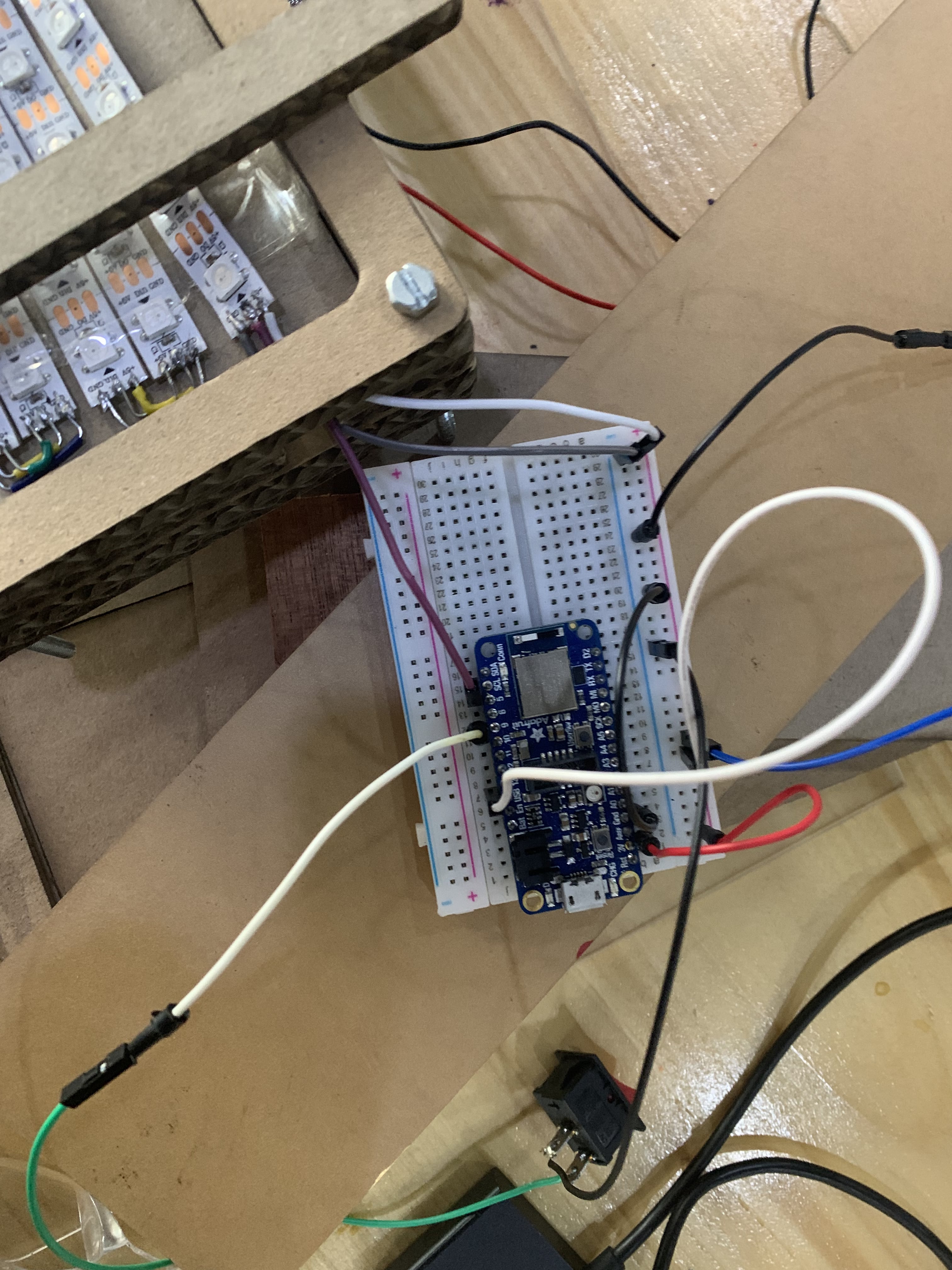
This is a close up of the LED connection
- Red Wire; from 3V to postive
- White Wire; from USB pin to ground
- Black Wire; from GRN pin to negative
- Pink Wire; from LED power to data pin 5
- Gray Wire; from LED GRN to negative
- Other White Wire; from LED 5V to positive

This is the battries connection, I had four 1.5 V battries to supply power to the clock. However while I was testing I used the power from USB. In general the clock need 5 V to work.
- Battries postive to board positive
- Battries negative to board negative

This is the switch connection
- The switch ground to the board negative
- The switch positive to the data pin
This is the final circuit digram done in fritzing website.
The Code
I wrote the code from skratch with the help of Fab Lab team. I used input & output devices work as reference. To start the time it has to be inputed directly in the code as current time and then it will keep running smoothly. Also, I used the serial monitor to make sure that time was changeing and to to make sure that the switch is on or off.
I defined two matrixes with the help of excel; digit matrix and location matrix. The location matrix includes four locations for the houres ones and tens and for the minutes ones and tens. The digit matrix is a 0 & 1 matrix, it includes all the numbers from 0 to 9.


This is the final code 💻
//include library
#include <Adafruit_GFX.h>
#include <Adafruit_NeoMatrix.h>
#include <Adafruit_NeoPixel.h>
#include <FastLED.h>
#include <SoftwareSerial.h>


#define BUTTON_PIN 9     //The switch data pin
#define PIN 12           //The LED data pin
#define BRIGHTNESS 10    //The brightness, max is 255 96 is good
#define MatrixWidth 5    //LED matrix width
#define MatrixLength 17  //LED matrix length
#define LED_BLACK    0   //Turn off LED
#define LED_PIN     12   //The LED data pin defined twice
#define NUM_LEDS    75   //Total number of LED


// Setting Current Time
int currentTimeHours = 20;
int currentTimeMinutes = 35;


CRGB leds[NUM_LEDS];


//LED matrix start from bottom left, and it is in zigzag pattren
Adafruit_NeoMatrix *matrix = new Adafruit_NeoMatrix(MatrixWidth, MatrixLength, PIN,
    NEO_MATRIX_BOTTOM     + NEO_MATRIX_LEFT +
    NEO_MATRIX_ROWS + NEO_MATRIX_ZIGZAG,
    NEO_GRB            + NEO_KHZ800);


//The digit matrix
int DigitMatrix [10] [15] = {

{1,1,1,1,0,1,1,0,1,1,0,1,1,1,1}, //Zero
{0,1,0,0,1,0,0,1,0,0,1,0,0,1,0}, //One
{1,1,1,0,0,1,1,1,1,1,0,0,1,1,1}, //Two
{1,1,1,0,0,1,0,1,1,0,0,1,1,1,1}, //Three
{1,0,1,1,0,1,1,1,1,0,0,1,0,0,1}, //Four
{1,1,1,1,0,0,1,1,1,0,0,1,1,1,1}, //Five
{1,1,1,1,0,0,1,1,1,1,0,1,1,1,1}, //Six
{1,1,1,0,0,1,0,0,1,0,0,1,0,0,1}, //Seven
{1,1,1,1,0,1,1,1,1,1,0,1,1,1,1}, //Eight
{1,1,1,1,0,1,1,1,1,0,0,1,1,1,1} //Nine

};

//The location matrix
int LocationMatrix [4][15] = {

{0,1,2,17,16,15,42,43,44,47,46,45,72,73,74}  //Min Tens
{4,5,6,21,20,19,38,39,40,51,50,49,68,69,70} //Min Ones
{8,9,10,25,24,23,34,35,36,55,54,53,64,65,66} //Seconds Tens
{12,13,14,29,28,27,30,31,32,59,58,57,60,61,62} //Seconds Ones

};


void setup () {
 FastLED.addLeds<WS2812, LED_PIN, GRB>(leds, NUM_LEDS);
 Serial.begin(9600);
 pinMode(BUTTON_PIN, INPUT_PULLUP);
}


void loop () {

 int minutes = millis() / 60000 ; // defining minutes using the function millis
 minutes = minutes + currentTimeHours*60 + currentTimeMinutes; // this is used to set the current time
 int hours = minutes/60; // defining hours using minutes
 minutes = minutes - hours*60; //minutes equation
 hours = hours - (hours / 24)*24; //hours equation

 // serial print some information to display in serial moniter to make sure that time is running
 Serial.println(minutes);
 Serial.println(minutes-(minutes/10)*10);
 Serial.println(minutes/10);
 Serial.println(millis());

 // separating the minutes tens and ones and the hours tens and ones
 int MINA = minutes/10;                // Minutes Tens
 int MINB = minutes-(minutes/10)*10;   // Minutes Ones
 int HOURA = hours /10;                // Hours Tens
 int HOURB = hours - (hours / 10)*10;  // Houres Ones


 // when the botton is ON turn on LED
 if (digitalRead(BUTTON_PIN)==0) {

 Serial.println("switch switched");  // serial print switch switched in serial moniter if the button is switched on

 // To show : always
 leds [59]= CRGB(150, 0, 255);
  FastLED.show();
 leds [25]= CRGB(150, 0, 255);
  FastLED.show();


// Display hours tens for loop
  for (int i=0; i<16; i++) {
    if (DigitMatrix[HOURA][i]==1) {
      leds[ LocationMatrix[4][i] ] = CRGB(150, 0, 255); // Houres Tens #
      FastLED.show();}
    else {leds[ LocationMatrix[4][i] ] = LED_BLACK;}
  }


// Display hours ones for loop
  for (int i=0; i<16; i++) {
    if (DigitMatrix[HOURB][i]==1) {
      leds[ LocationMatrix[3][i] ] = CRGB(150, 0, 255); // Houres Ones #
      FastLED.show();}
    else {leds[ LocationMatrix[3][i] ] = LED_BLACK;}
  }


// Display minutes tens for loop
  for (int i=0; i<16; i++) {
    if (DigitMatrix[MINA][i]==1) {
      leds[ LocationMatrix[1][i] ] = CRGB(150, 0, 255); // Min Tens #
      FastLED.show();}
    else {leds[ LocationMatrix[1][i] ] = LED_BLACK;}
  }


// Display minutes ones for loop
  for (int i=0; i<16; i++){
    if (DigitMatrix[MINB][i]==1) {
      leds[ LocationMatrix[0][i] ] = CRGB(150, 0, 255); // Min Ones #
      FastLED.show(); }
    else {leds[ LocationMatrix[0][i] ] = LED_BLACK;}
  }


}

//when the botton is OFF turn off LED
else if (digitalRead(BUTTON_PIN)==1) {
  FastLED.clear();
  FastLED.show();
  }
}
Part2: The Design
CAD Deisgn Prototype
CNC Milling Wood Finishing Laser Cutting
CAD Design
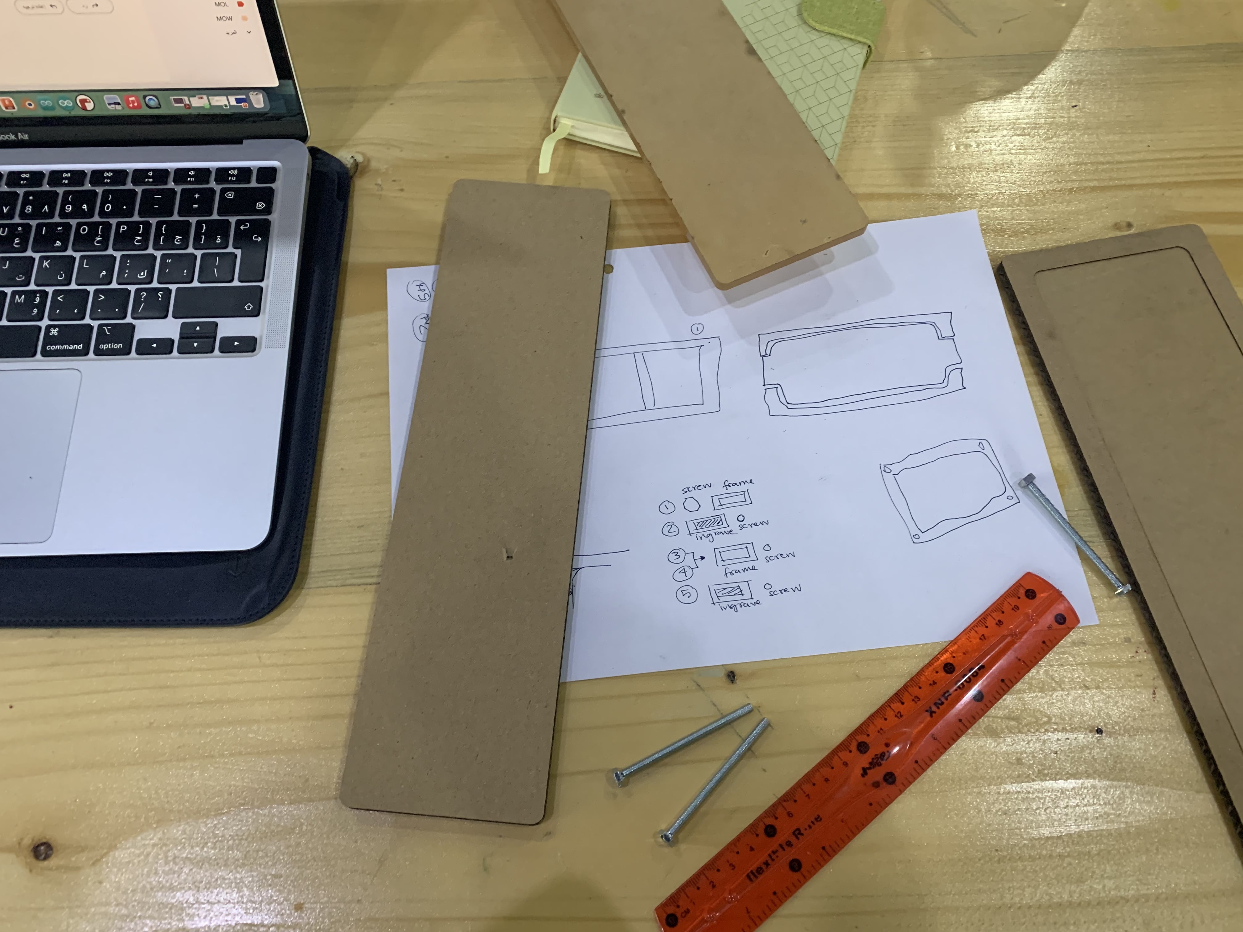
Before I started the CAD design I brainstormed multiple ideas for the clock 🕰️ design, I wanted it to be rectangular, made out of wood, and has an acrylic front. After many discussions and advice this is the sketch of the design I settled on.

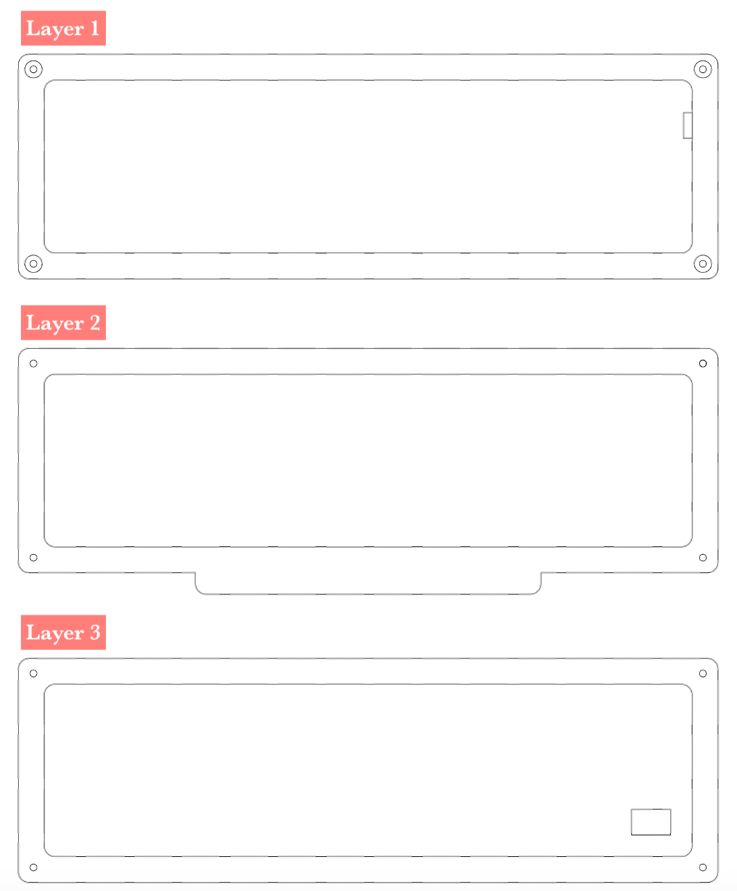
The design includes 3 layers of a good quality wood that is almost 18 mm in thickness
- Layer 1; includes the acrylic front and the LED strip lights grid
- Layer 2; includes the arduino board and battries and it is ingraved all the way through
- Layer3; includes the arduino board and battries, it is ingraved by 10 mm and it has the switch at the back
After coming up with the idea, and sketching the design , I started to design the components in Fusion360.
💡 Before you start designing here is a helpful tip to make your design parametric, it will make editing mistakes so much easier instead of changing every dimension yourself.
💡 Another tip is that you only need the DXF file to use CNC machine or the lazer cutting machine, and in CNC machine programe, VCarve you can make small edits and adjustments like adding an offset, so you do not really need to do the design in 3D but it is helpful to envision the design.
These are the drawings of the three layers of the clock 🕰️. Click to download the dxf files of Layer 1, Layer 2 and Layer 3.
Prototype
Before applying the design using the CNC machine, I made a prototype using 6 mm thick cardboard cut using the lazer machine. This is how the prototype assembled looked like. It is assembled by 4 screws on each corner.
By creating a prototype, you can actually hold a version of the proposed product and determine what aspects do its job and which ones need refining. This is a chance to gather more accurate requirements and obtain some feedback.
By doing the lazer cut prototype I checked if the screws would fix, checked the fitting of the acrylic layer, the fitting of the LED grid, the fitting of the electronic parts, and in gereal if the size is good.
After cutting the main body of the clock I wanted to see what is more suitable to display and diffuse the LED lights. This is with milky acrylic.
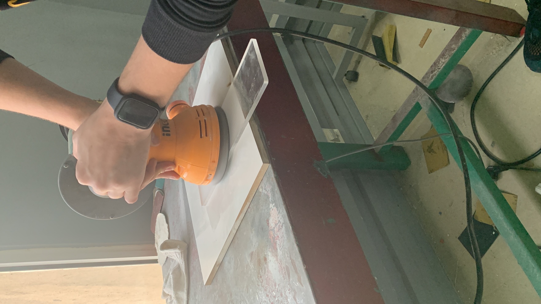
I lazer cut a clear acyrlic piece then sanded it down to make it more diffussed.

This is with clear sanded acrylic only.
This is with clear sanded acrylic with white fabric underneath.

This is with clear sanded acrylic with tissue underneath.
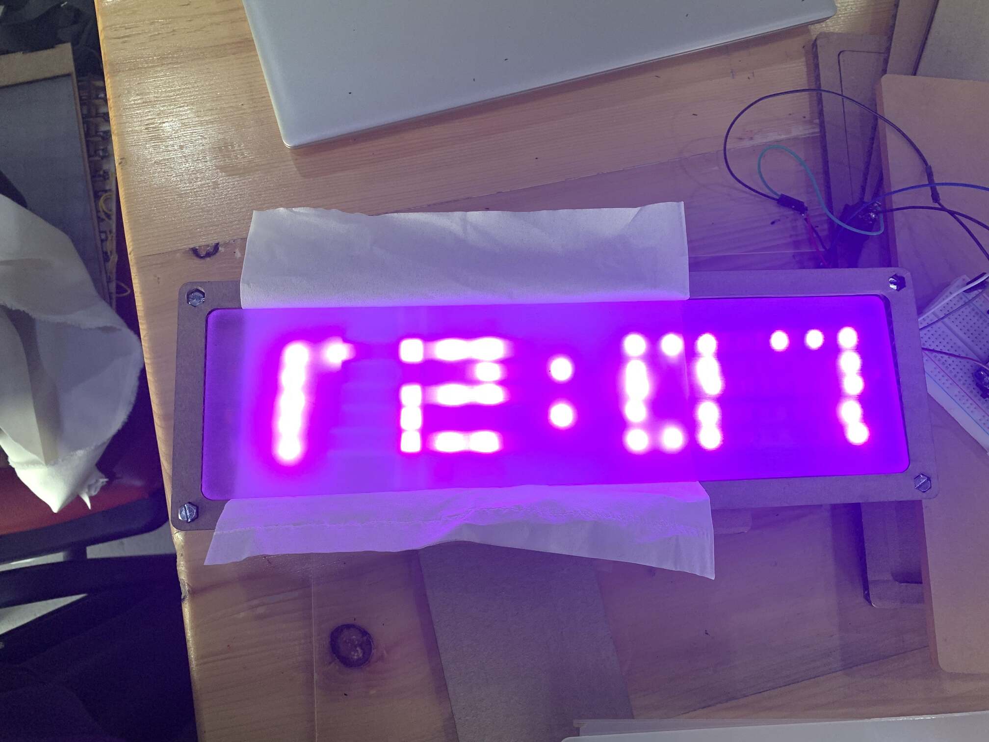
At the end I settled on the milky acrylic as the best option.
This is how my work table looked like.
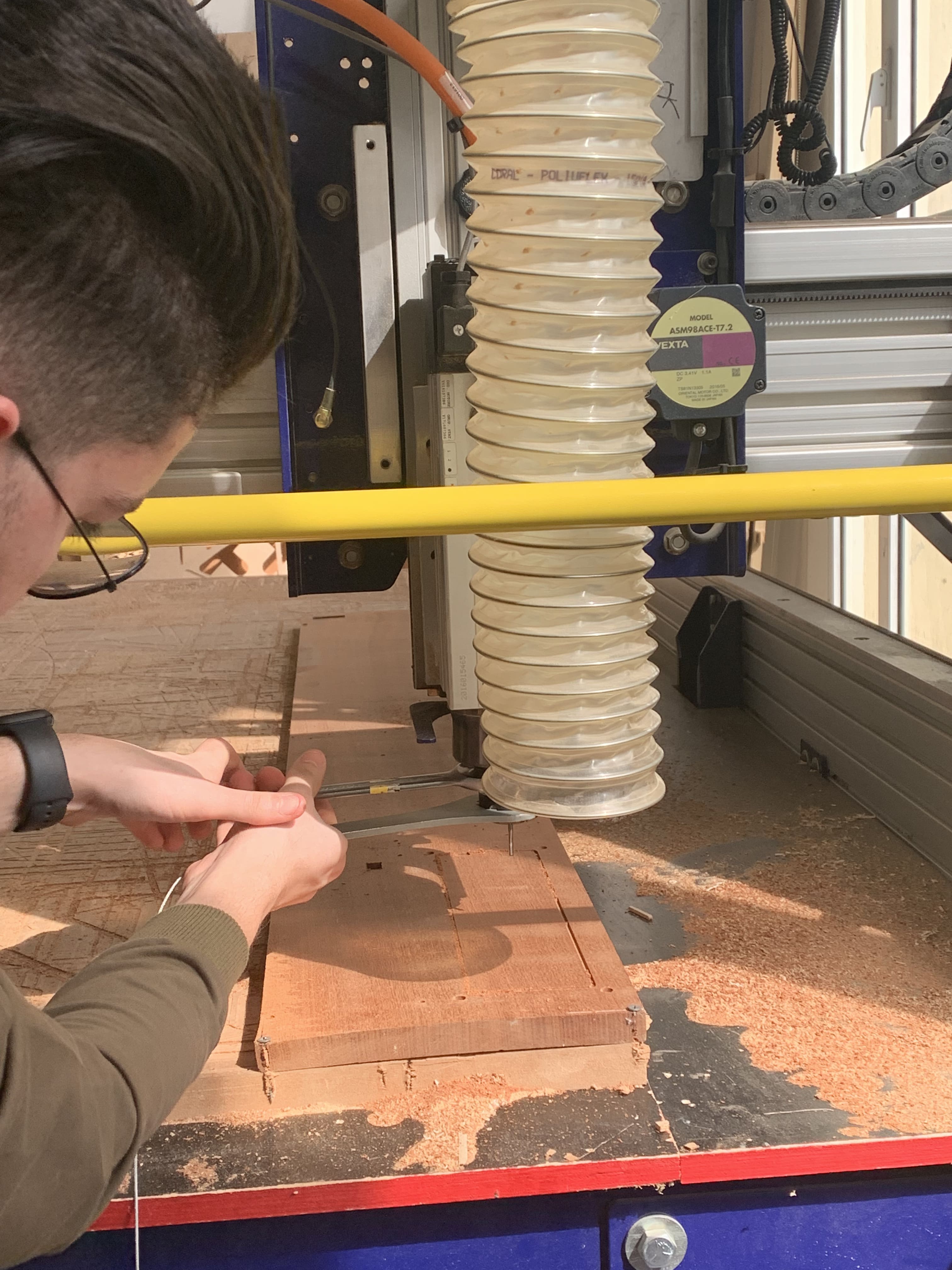
CNC Milling
After the prototype, I moved to cutting using the CNC machine. First thing I secured a piece of wood and zero the z axies to the machine bed.
First Tool Path
I imported the DXF file to VCarve. For the first tool path we are using a smaller drill pit (1/4’‘), so I selected the screw and switch openings and the acyrlic offset. I modified/added the offset in VCarve.

I selected cutting from the inside and added tabs.
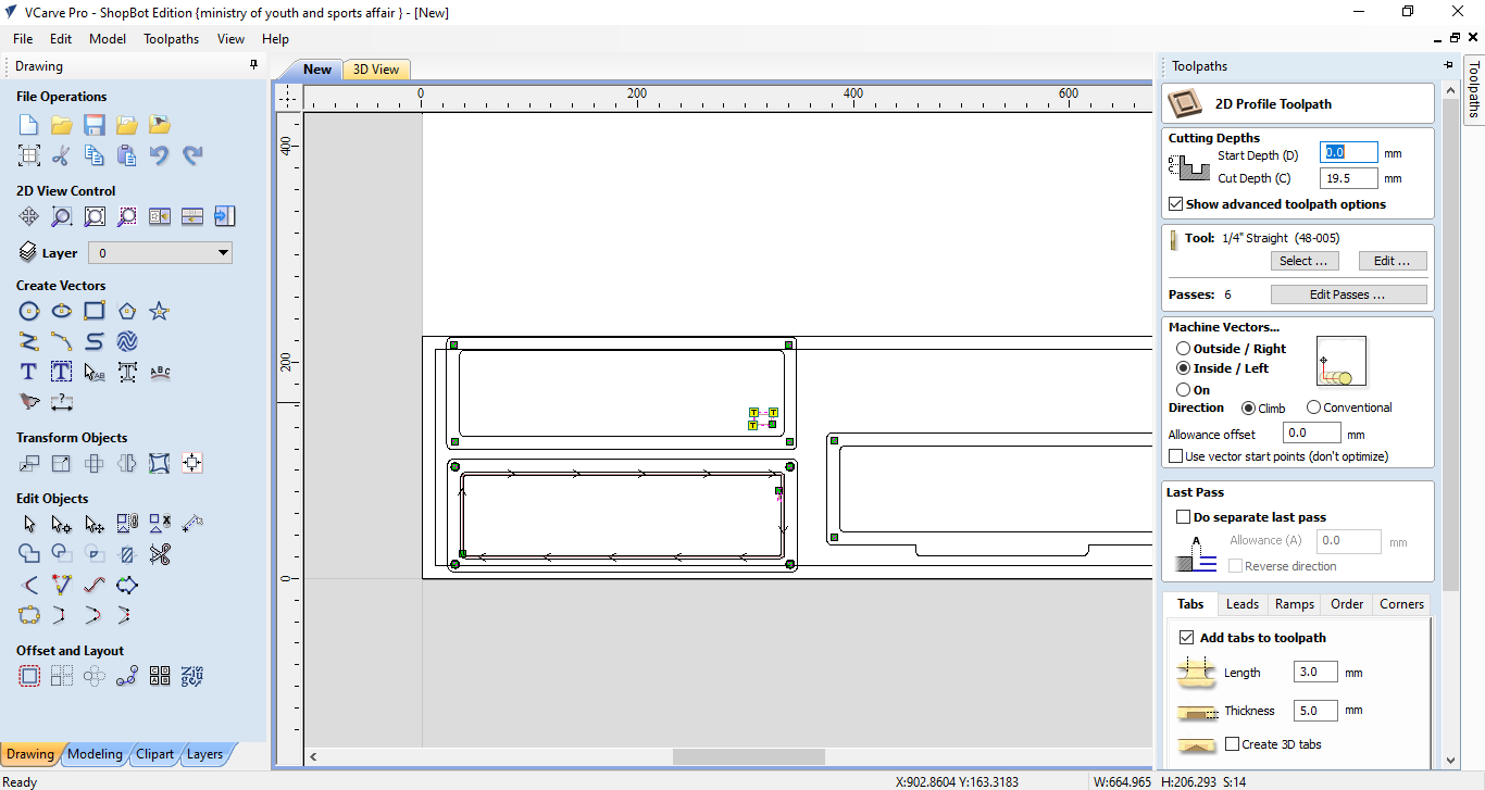
This is the first tool path result.

Second Tool Path
we changed the drill pit to a bigger size (1/2’‘) to make it easier and faster for the machine to engrave the pockets.
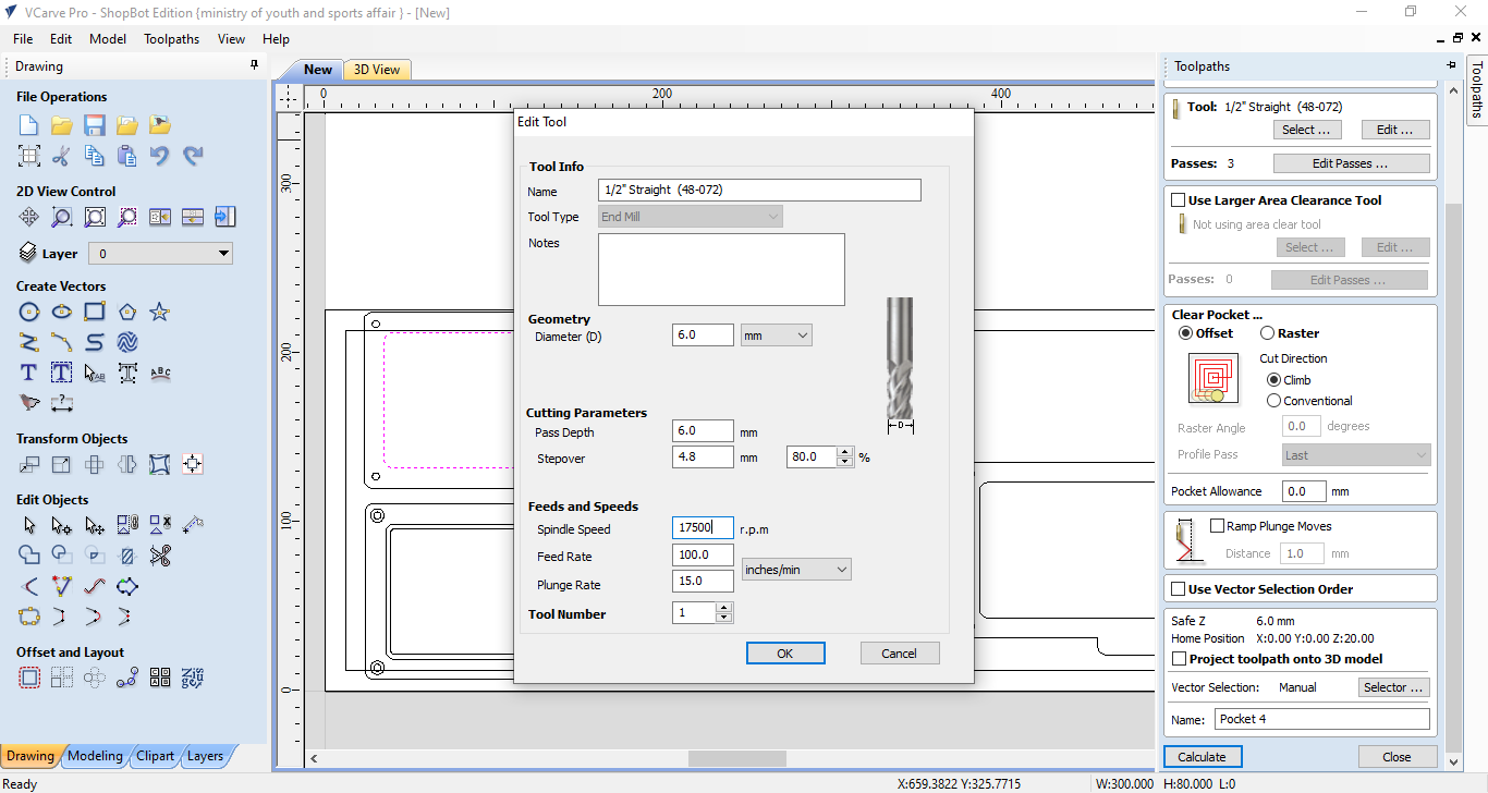
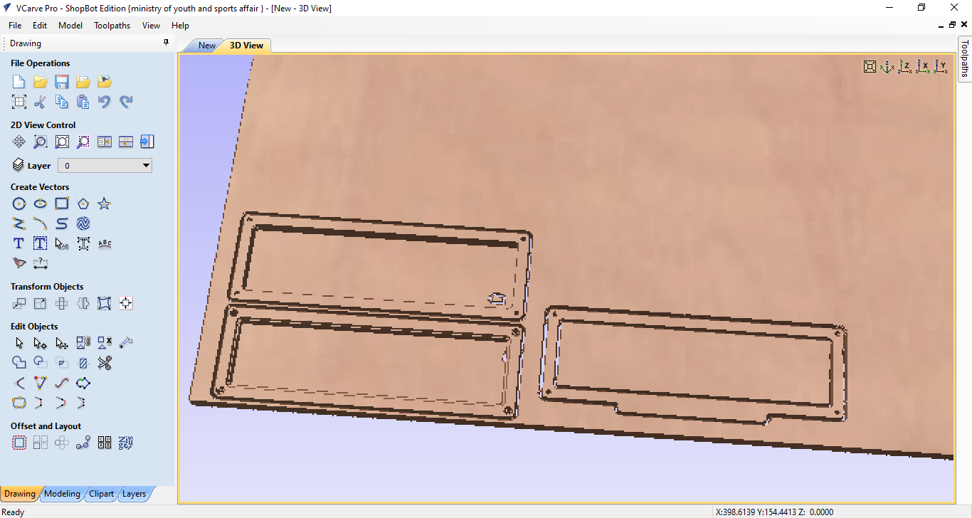
I selected where I want to engrave the pockets for each layer.

This is how the pockets result looked like in the program.
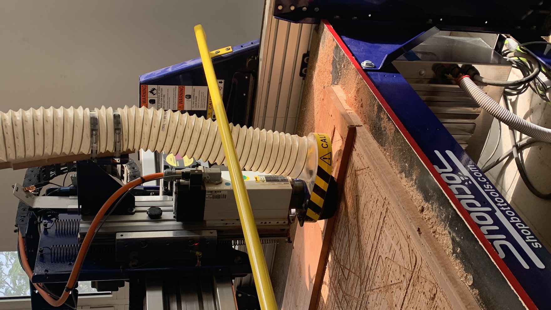
This is the CNC machine engraving the pockets.
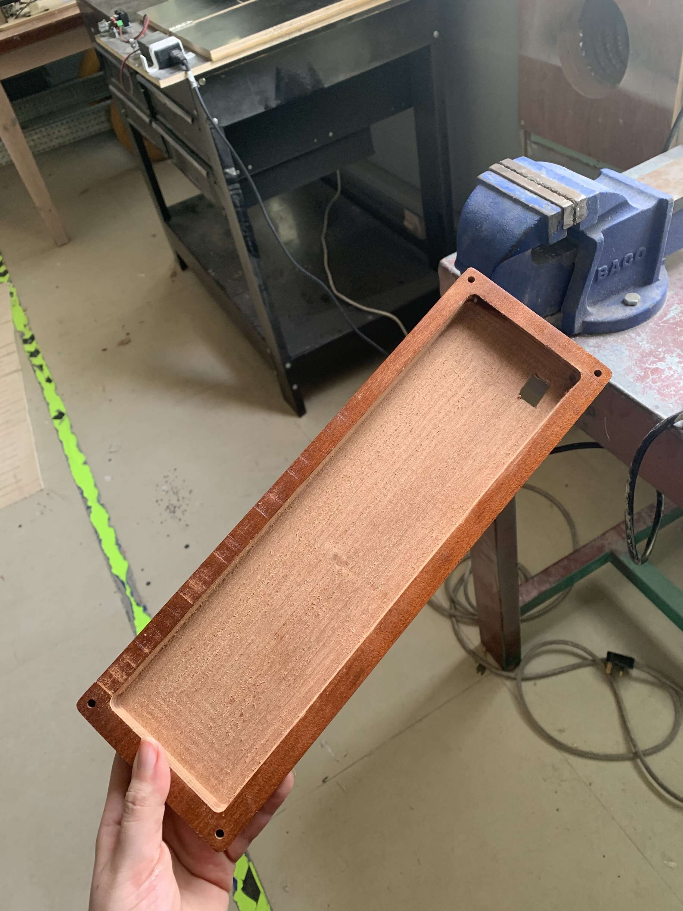
CNC Final Result

Wood Finishing
After the cutting the three layers using the CNC machine, the wood need some finishing touches which are sanding and waxing.
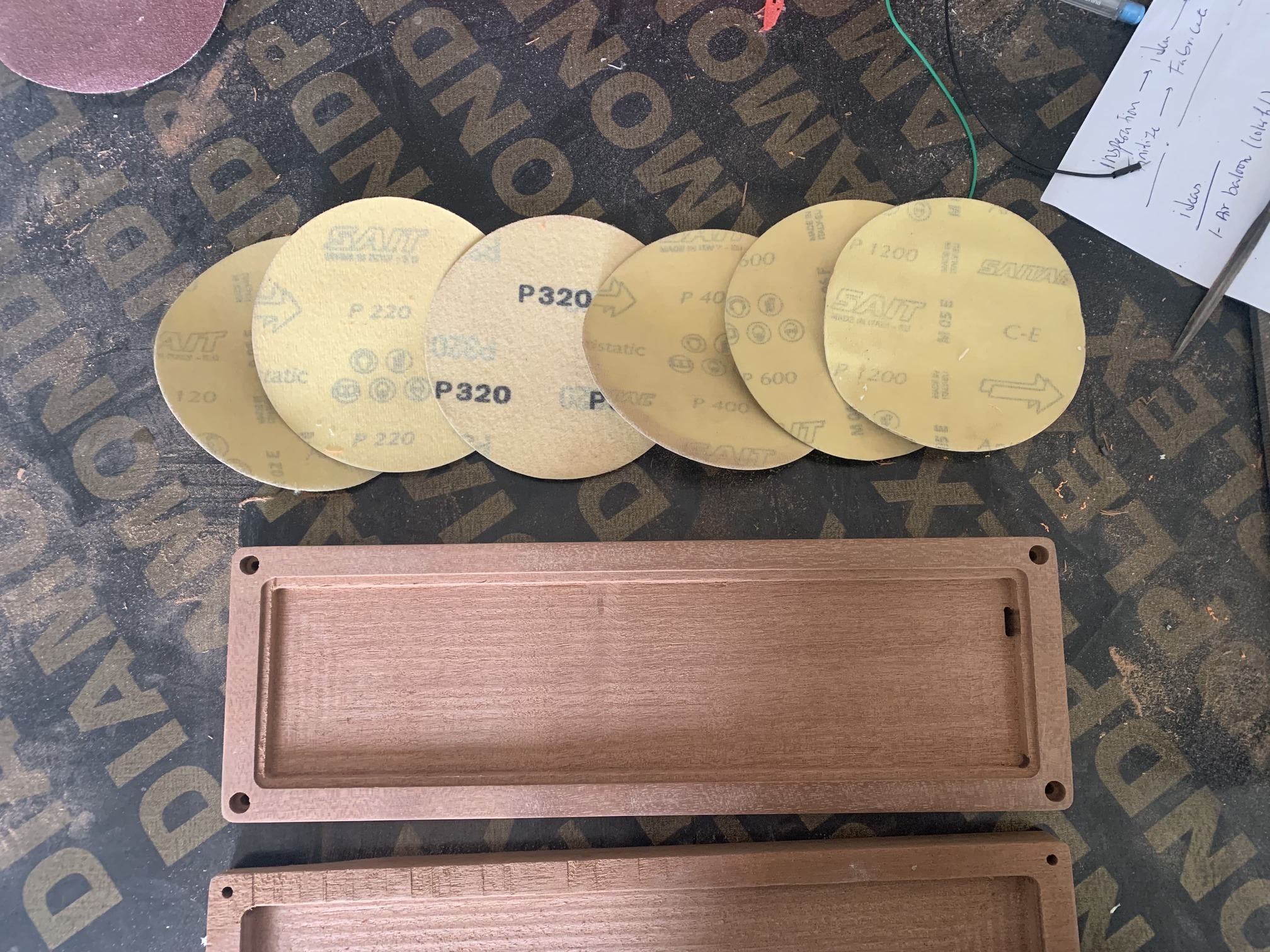
Sanding
I used multiple sanding paper levels to give the wood the best wood finish. I used in order P120, P220, P320, P400, P600, and P1200 to make the three layers as smoothe as possible.
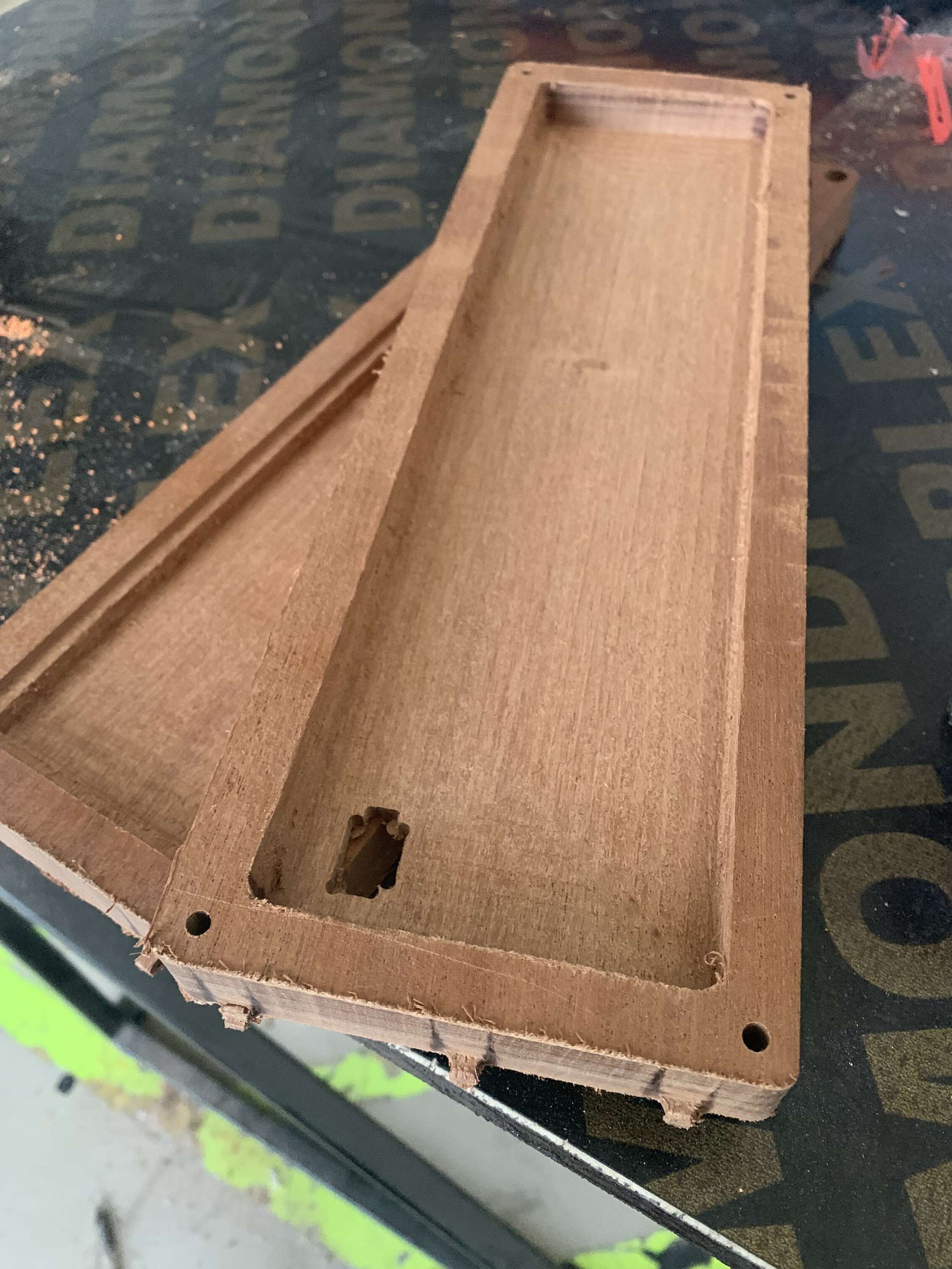
While using the CNC machine I added tabs to the frame of each layer, this is what was left from the tabs.
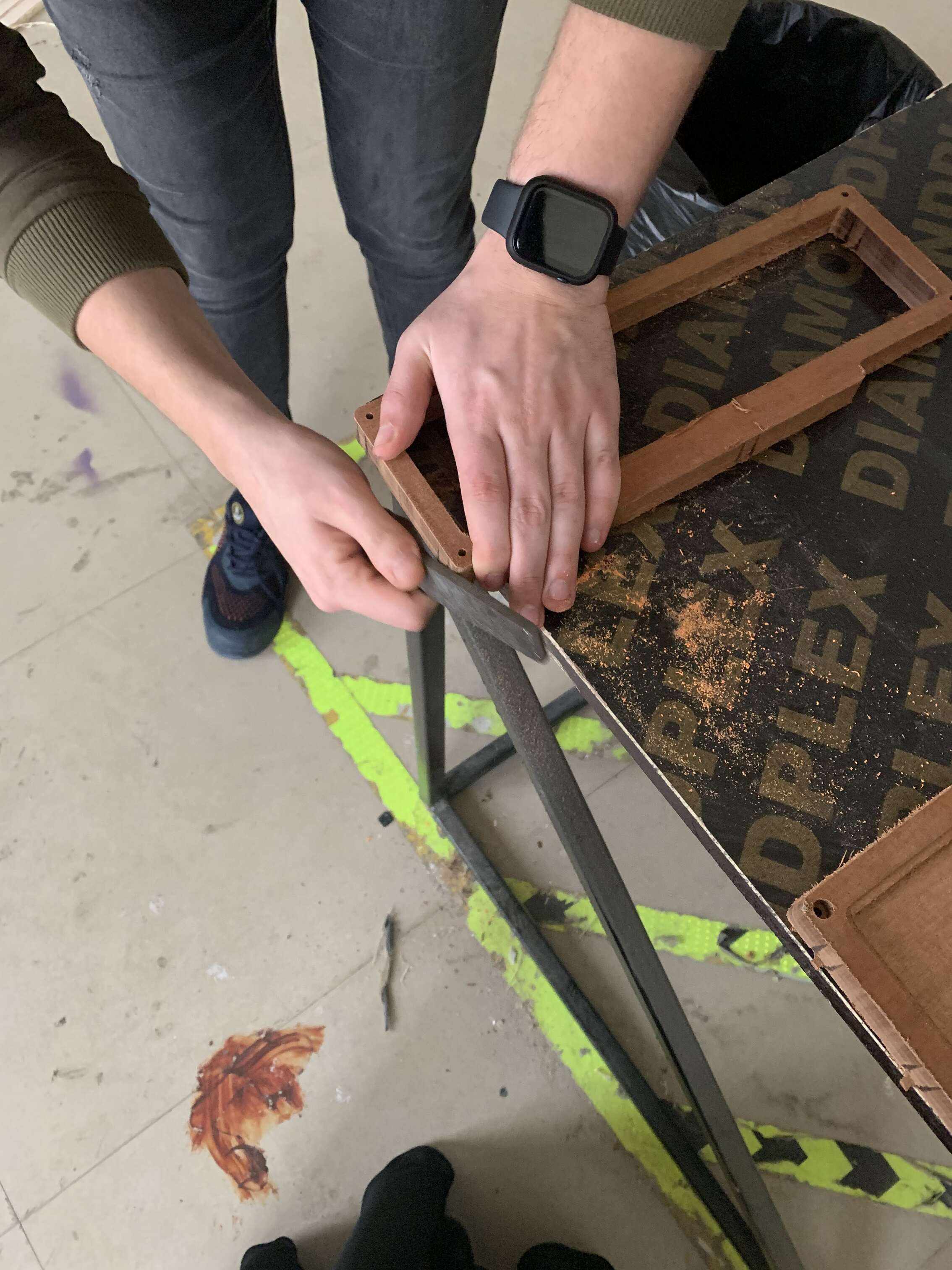
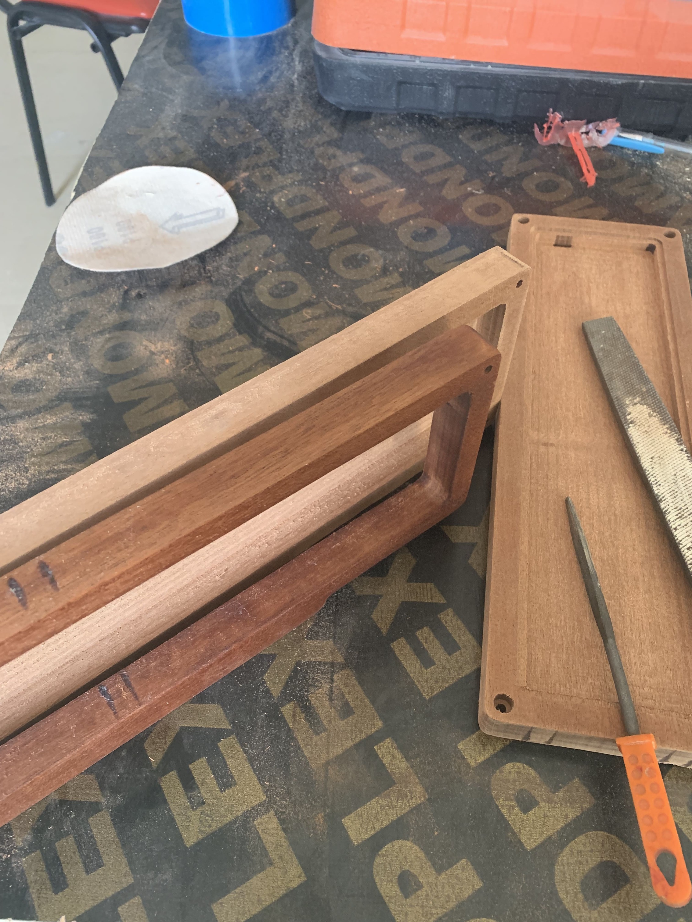
To remove the tabs we secured the piece of wood to the edge of the table and used wood file to smoothe the tabs.
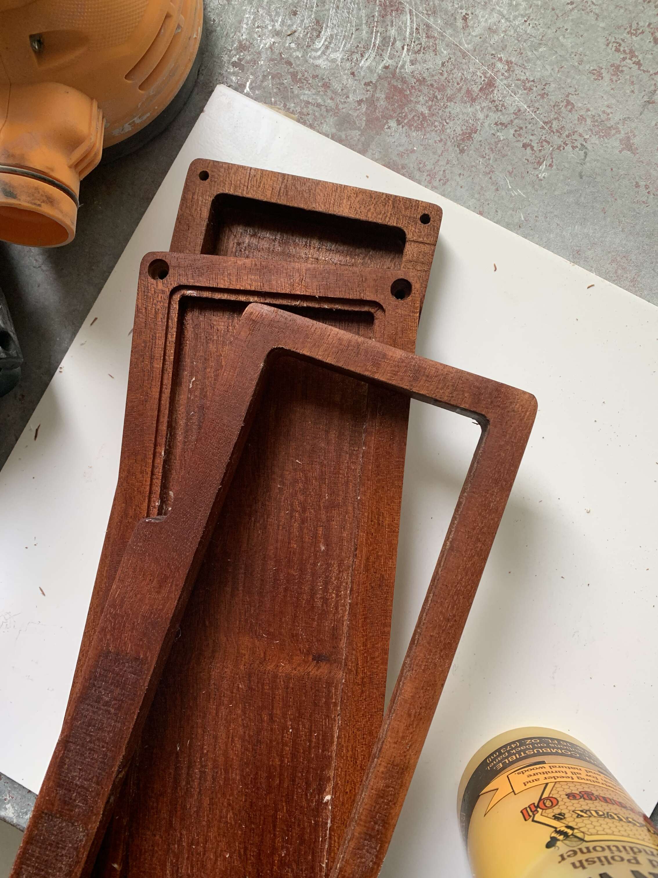
Waxing
For waxing the wood, I used this beewax 🐝 and orange oil wood polish and conditioner.

Here you can see the difference before and after applying the wax.
I loved how the result tured out 😍.

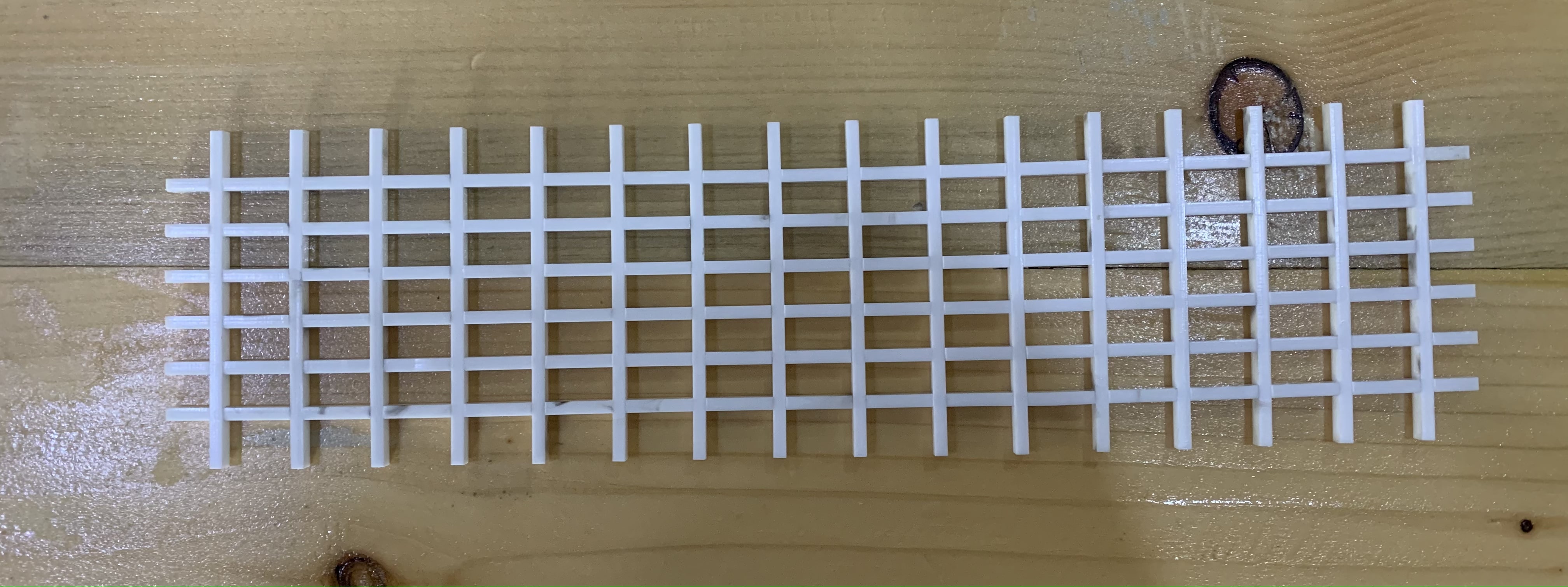
Laser Cutting
To make the LED light difusse nicely I added a grid made out from white 3 mm acrylic, cut using the laser cutting machine. After multiple attempts as you can see here, I finalized the design.

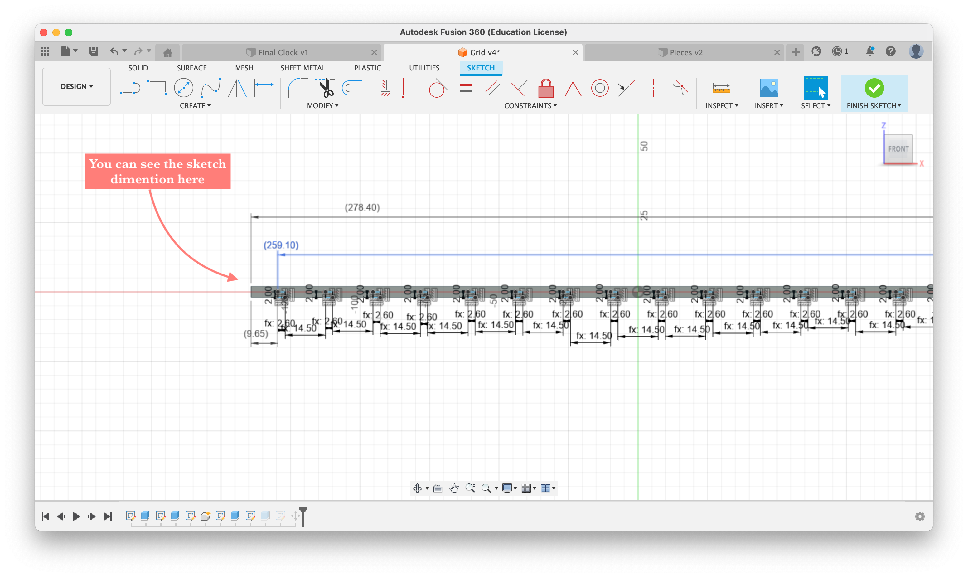
Here is the design in Fusion360, again make the design parametric for easy modification.
This is the vertical grid, here you can see the dimensions and you can download the DXF file from here.

This is the horizontal grid, here you can see the dimensions and you can download the DXF file from here.
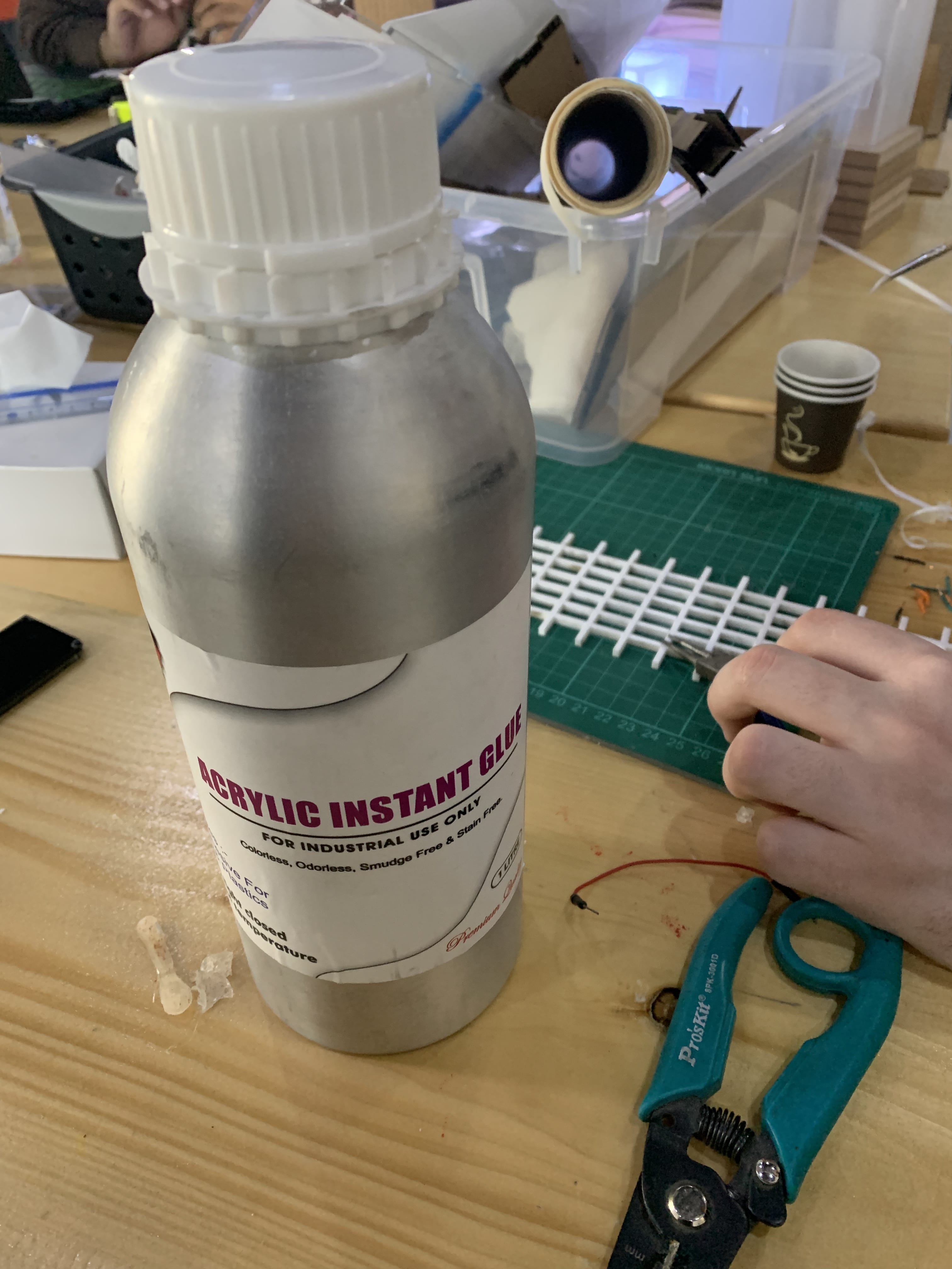
To keep the grid togather and make it stronger I used acrylic instant glue.
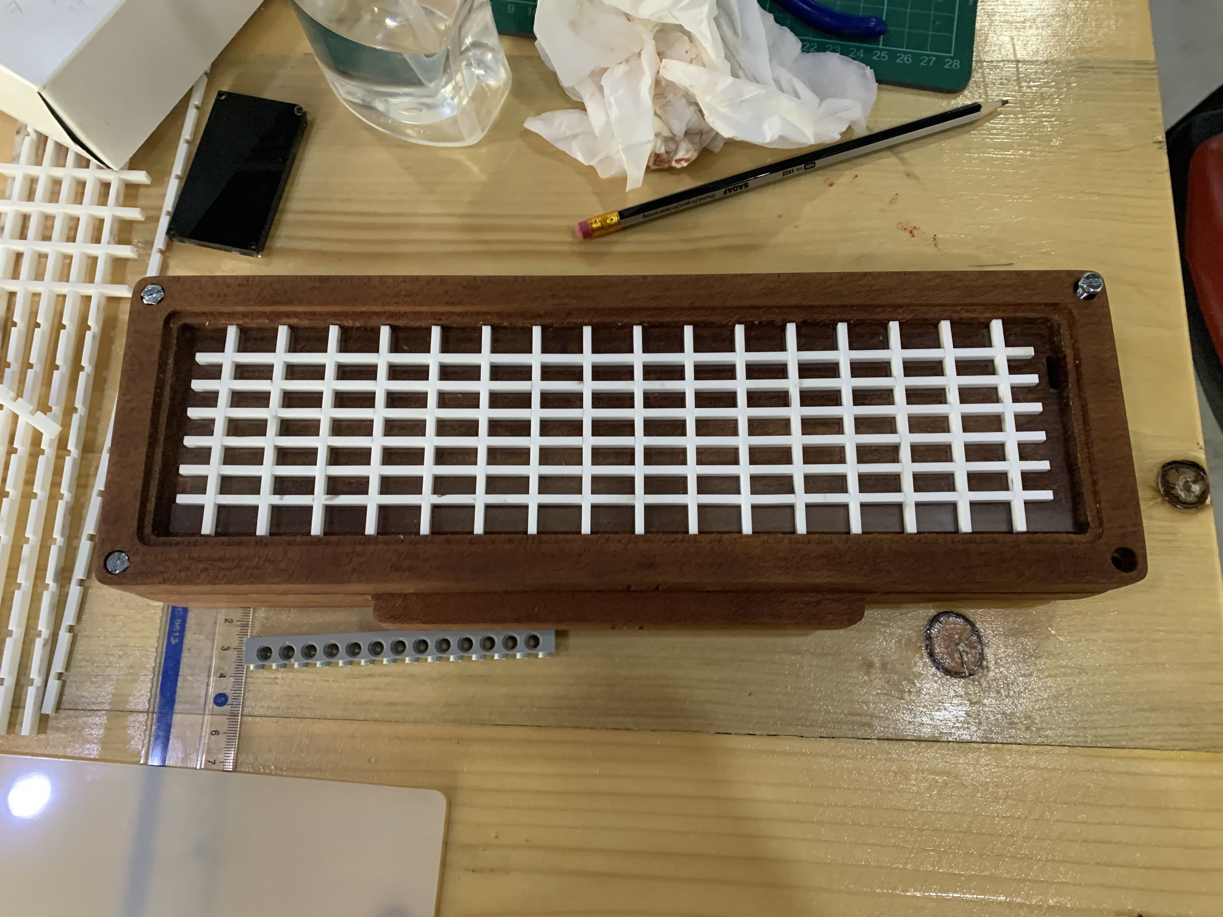
This is the grid.
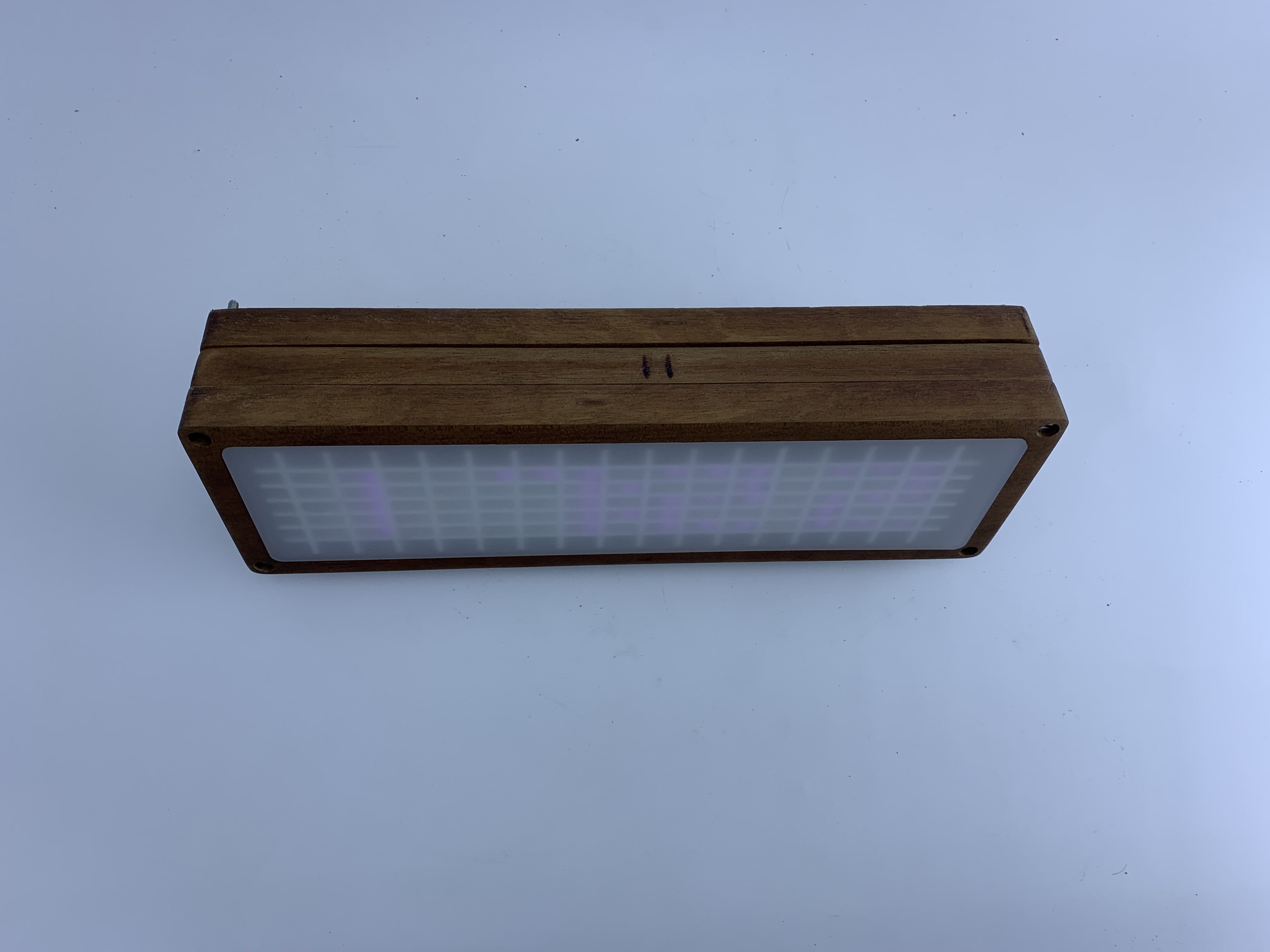
This is how the grid fit inside the clock.
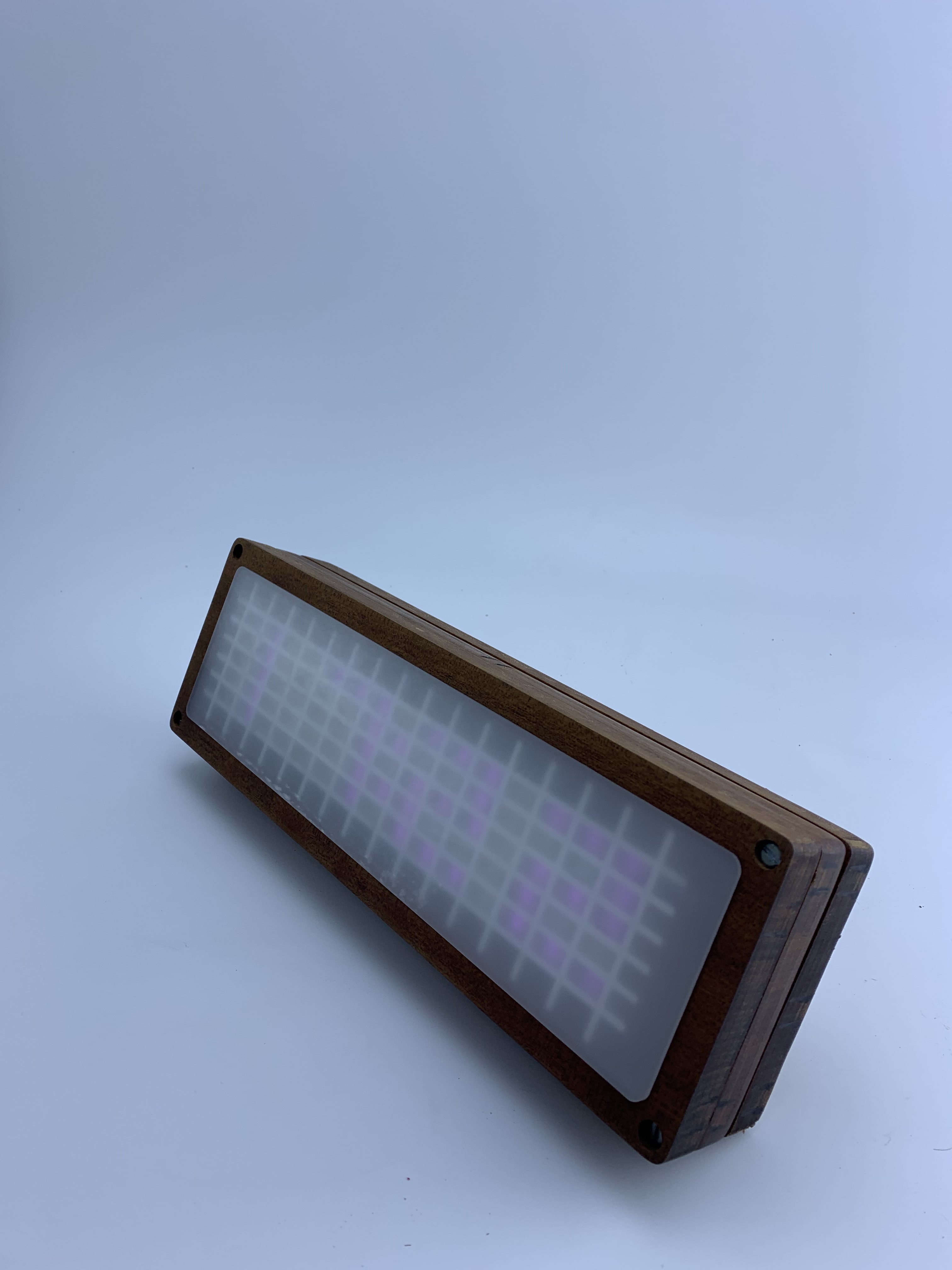
This is the grid under the acrylic piece.
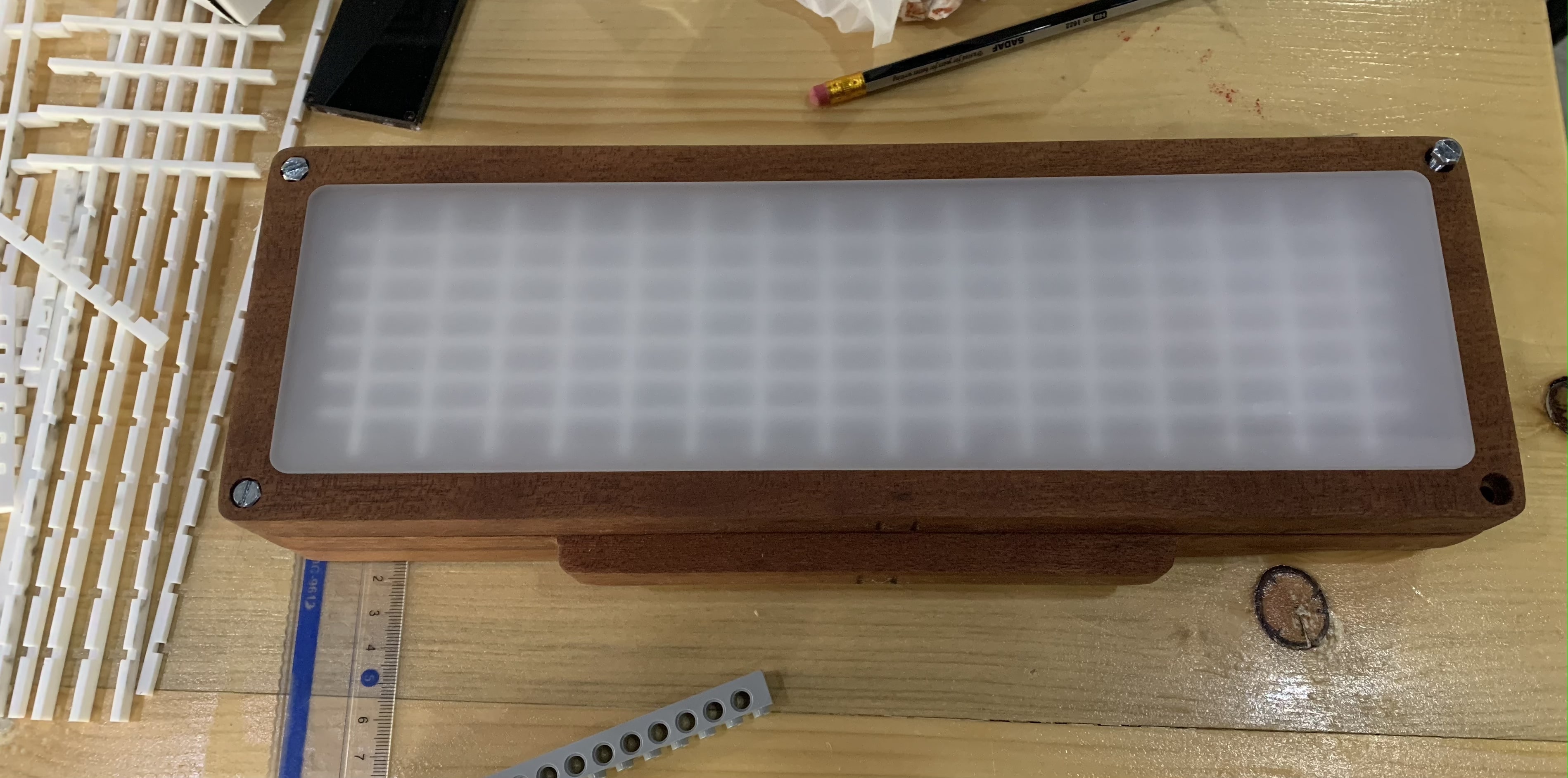
Finally, assembling the electronics inside the clock.

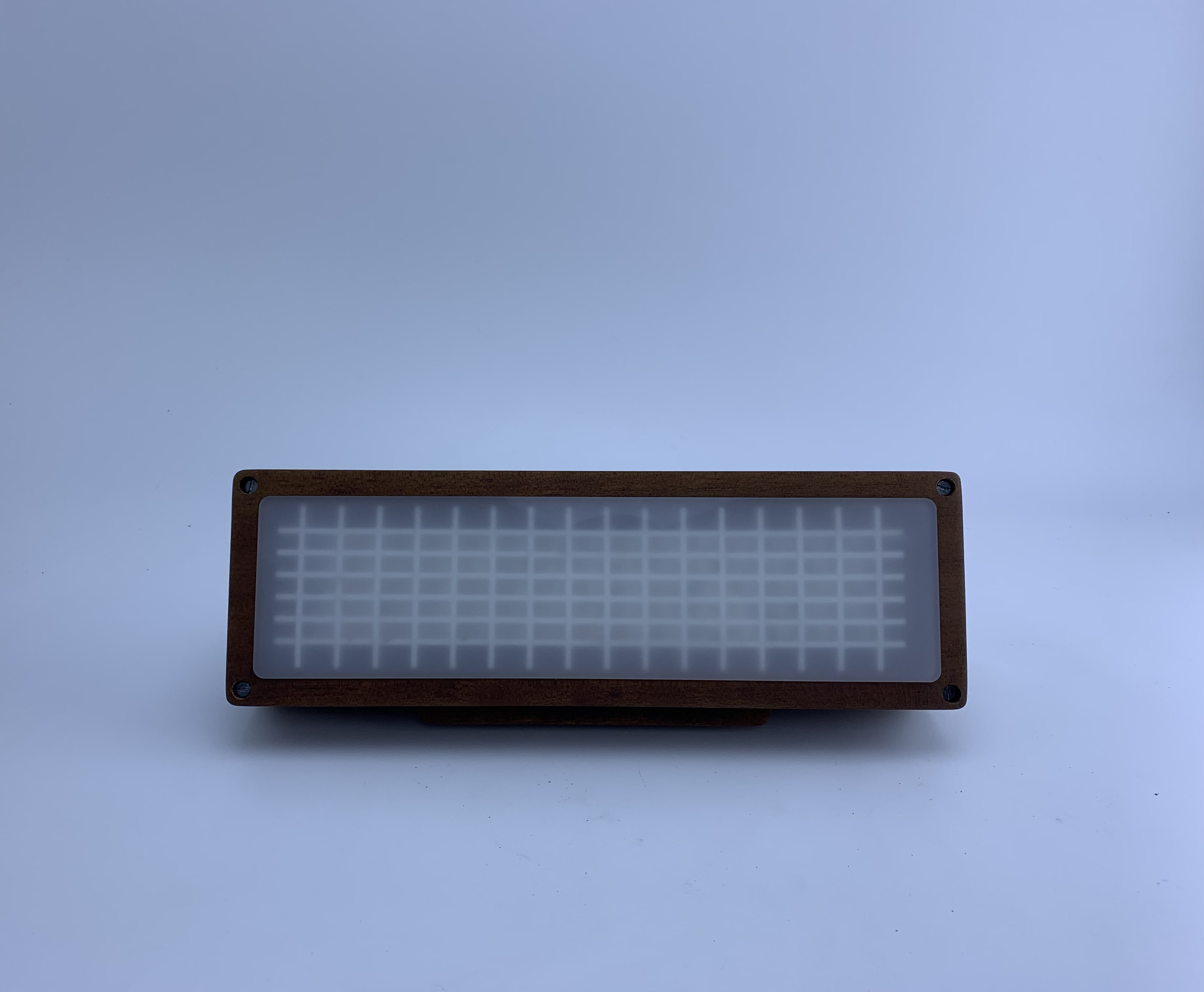
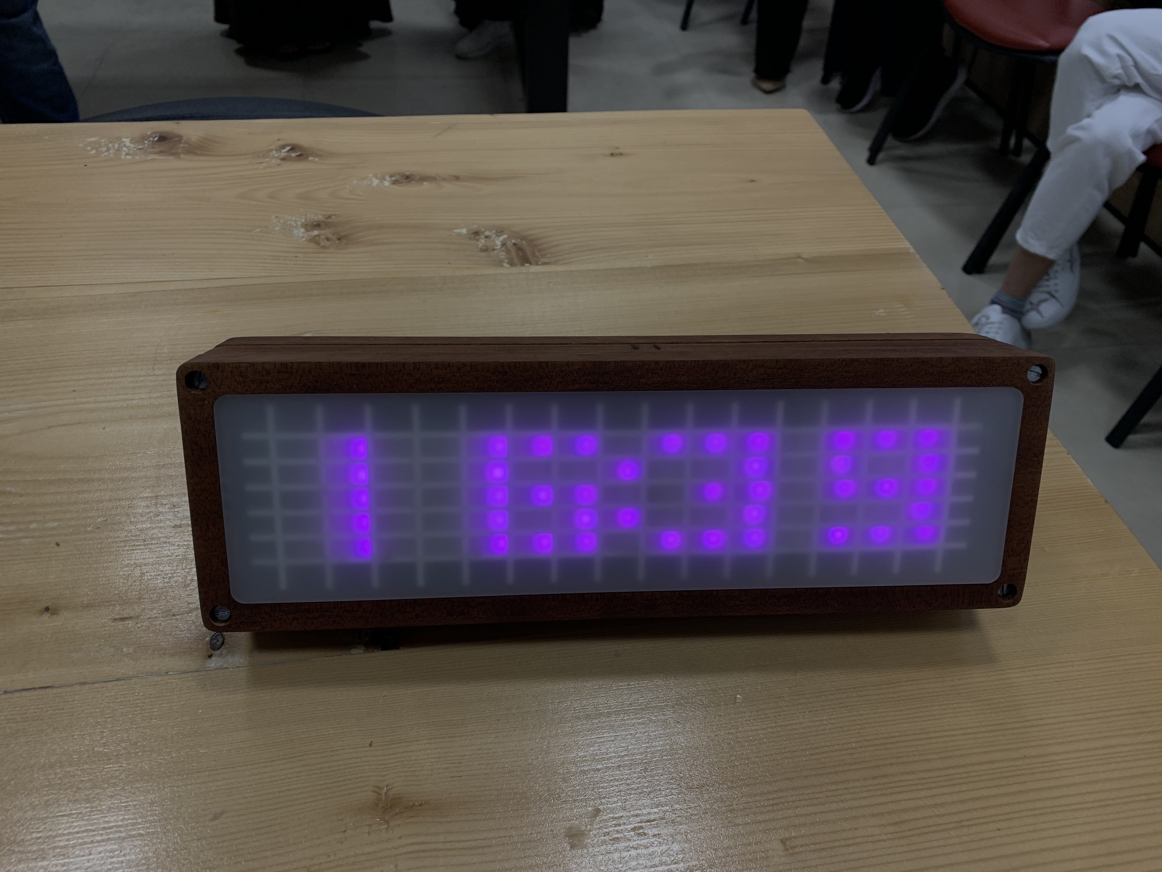
The Final Result
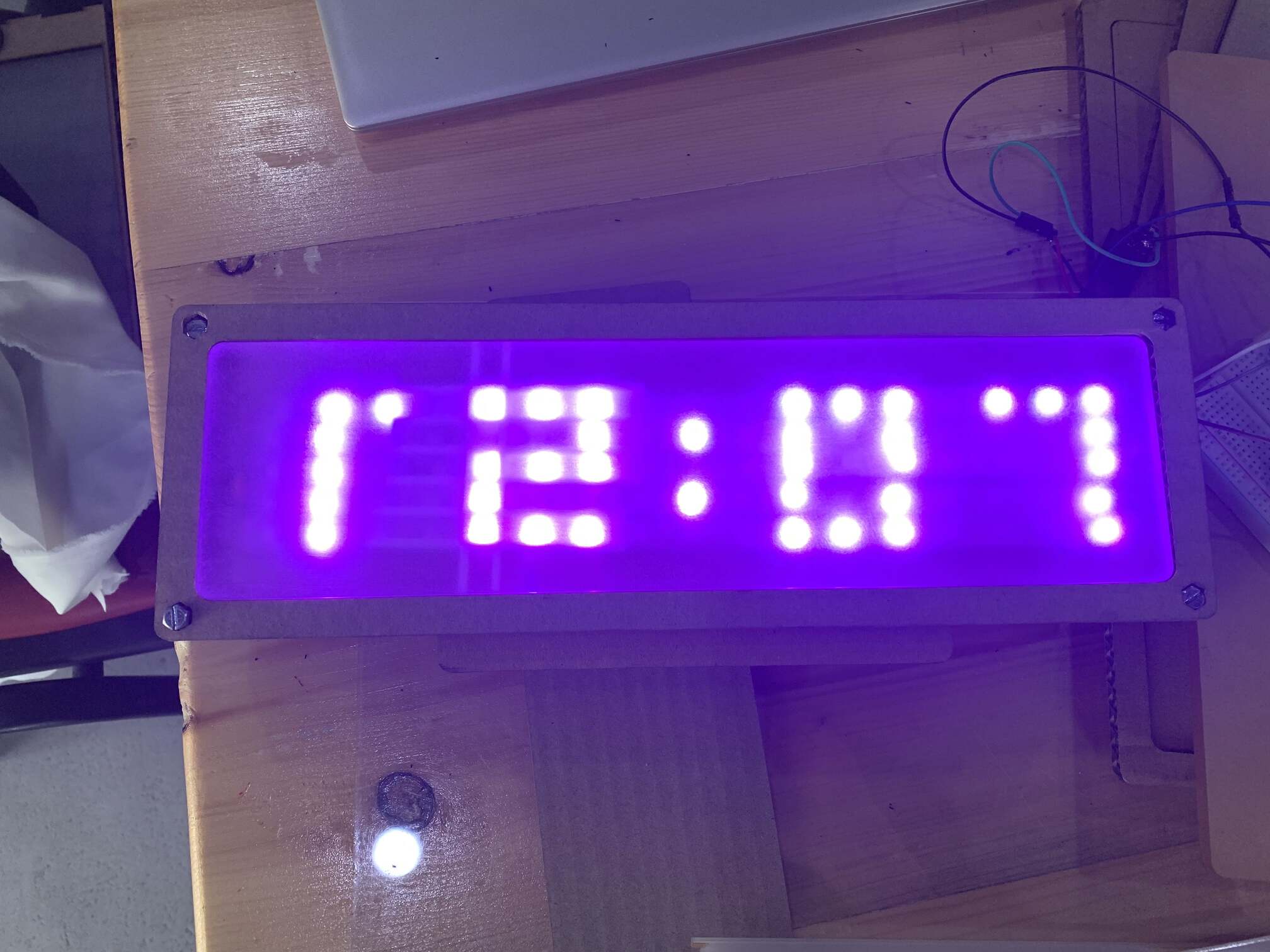
This is the final result of the clock 🕰️✨

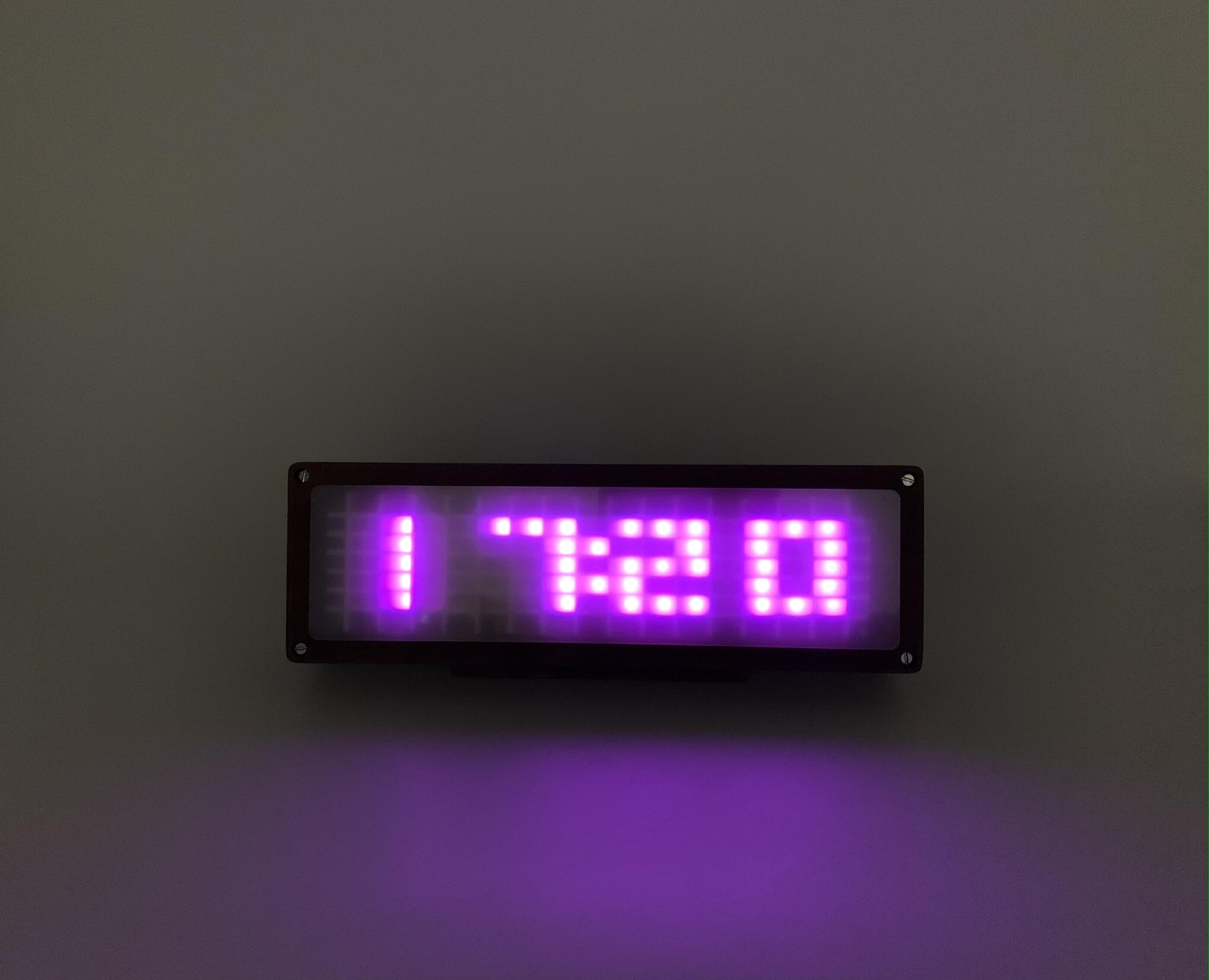
These are short videos that show the clock 🕰️ working ✨

Future Work
Although I am happy with the project’s outcome, there is yet room for developments in the future.
- I could make the clock display text too, like reminders or messages between two people.
- I can include a display of the date and day.
- I can make the color of the lights changeable.
- The clock now is standing with the help of the screws where as it should be standing on the angle part of the second layer.
- To fix any electronic component or to replace the batteries, all four screws has to be removed and the clock will be disassembled. Therefore, I should make it easier to change the batteries from the back.
Summary
Acknowledgement
I would like to express my greatest appreciation to the Fab Academy team 🤍 for their continuous support and help during the last 10 weeks. Especially during the last 2 weeks developing my final project.
- I would like to thank Abdalgfor Ismail for helping with the design of my project using the CNC machine.
- Thanks to Haitham Al Nasser for helping me with the electronics and programming part and fixing my many mistakes with the code.
- A great thanks to Duaa Alaali for helping and guiding me with the code and electronics.
- Thanks to Salman for guiding the project to success!
- And I would like to thank Abdullah Albaitam for helping with the project.
- Special thanks to Sayed Alawi because I tested my code on his project.
Without their guidance and support, the project may not have achieved its success. Their contributions were truly appreciated 🤍🙏🏻.
Design Files
Here is the original design files:
- Clock 🕰️ Layer 1 DXF File
- Clock 🕰️ Layer 2 DXF File
- Clock 🕰️ Layer 3 DXF File
- Vertical Grid DXF File
- Horizontal Grid DXF File
- Acrylic Front DXF File
- Summary Picture
- Summary PDF