5. Large Format CNC (Computer Controlled Machining)
This week I worked on making (designing, milling, and assembling) something big 💡, using CNC machine.
- Group assignment: Test runout, alignment, speeds, feeds, toolpaths for your machine and document your work
- Individual project: Make (design+mill+assemble) something big
Group Assignment
For the group assignment we had to test alignment, speeds, feeds, and toolpaths for the CNC machine. It is linked here in Sara’s website.
Individual Assignment
Coming Up With The Design
This week individual assignment was to make something big 💡 using the CNC machine. So we should design, mill and assemble something big. The only limit was that we will have to work with one sheet of plywood provided. Also, we had some rules including that we cannot use glue, screws or nails, we should only use joints.
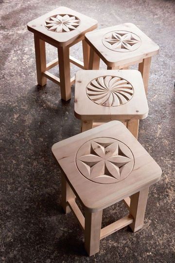
I search the web for inspration, and I was excited by all of the ideas I came across until I found a stool image on Pinterest and I really liked it. This is the image.
And from here I started sketching the design and thinking about how to put it togather. First I had to know what is the material I will be using. We used a plywood board 120mm in width, 240mm in length, and 12mm in thickness. Plywood is a strong material specially compared to MDF. From this point I started sketching the design and thinking about how to put it togather. Here are some of my first sketches. See more of my sketches here.
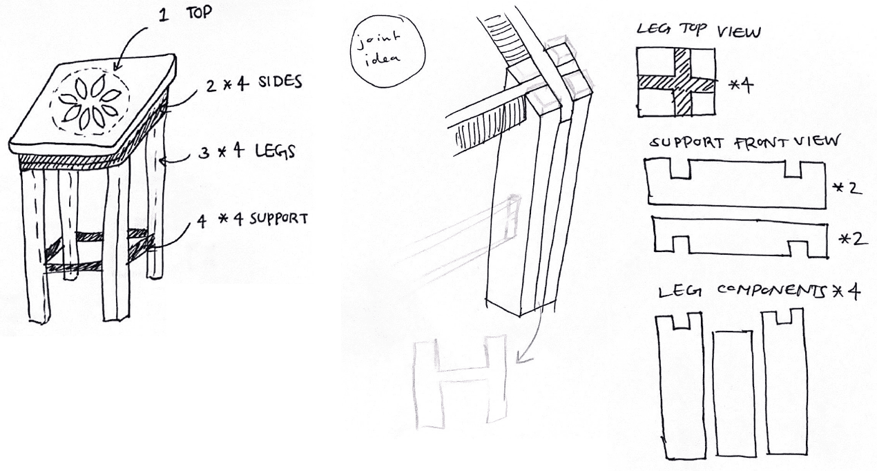
During the sketching process I had to decide what type of joint to use. So I searched about joints and the joint ideas I had were as follows:
- Halving Joint
- Mortise And Tenon Joint
- Tongue And Groove Joint, look here
- Dovetail Joint, look here
- Lap Joint
- Box Joint
- Castle Joint, look here
I ended up using the castle joint and mortise and tenon joint.
I was looking for a strong joint for the legs so the stool can handle the weight of the person sitting on it so I used the castle joint. The castle joint, is created by combining an intersecting bridle joint and a half lap cross joint to create a three-way interlocking joint. The castle joint is one of the strongest woodworking joints because of how well these two joints work together to create a very strong overall relationship. The manner in which the wood pieces are put together ensures the joint’s strength and enhances its aesthetic look. The castle joint is among the simplest woodworking joints, regardless of the fact that it appears complicated.
In addation, I used mortise and tenon joint in the leg support and to attach the leg parts to the top. The mortise and tenon joint has excellent stability, it’s a relatively simple joint, yet it holds well. It has been used for generations because of its strength, versatility and simple design.
At the end the stool parts will be as follows:
- Flower Top
- Plain top
- H Shaped Legs ×2
- Other Part of Leg ×8
- Leg Support ×2
- Top Support ×4
The Design in Fusion360
After coming up with the idea, sketching the design and deciding on the joint, I started to design the components in Fusion360. Before you start designing here is a helpful TIP💡 to make your design parametric, it will make editing mistakes so much easier instead of changing every dimension yourself
- Step1, save the file, from the main file create component, you should creat a new component for each part of the design
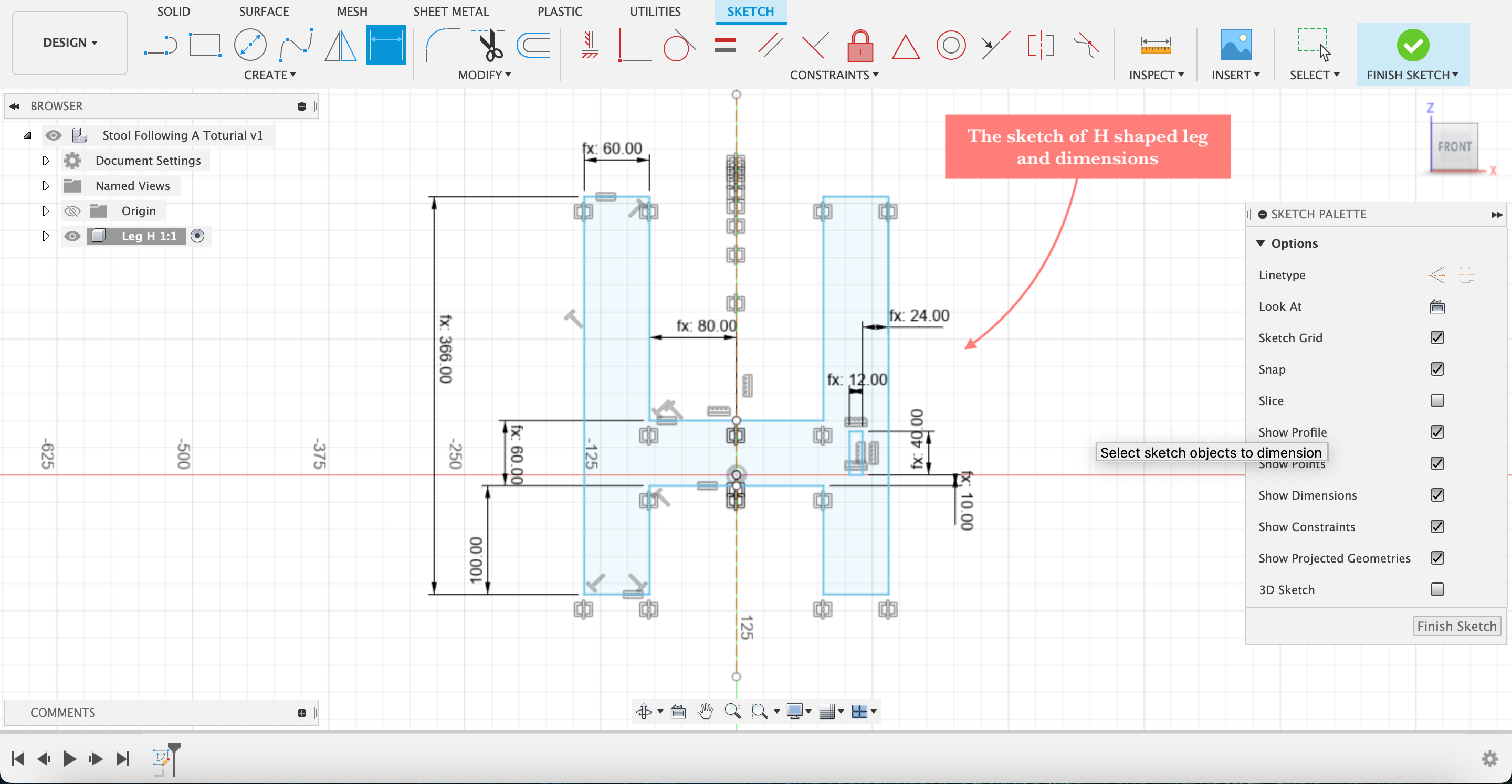
Creating The H Shaped Leg
- Step2, creating the H shaped leg; create a sketch, use a construction line to mirror the sketch, and fix the dimensions
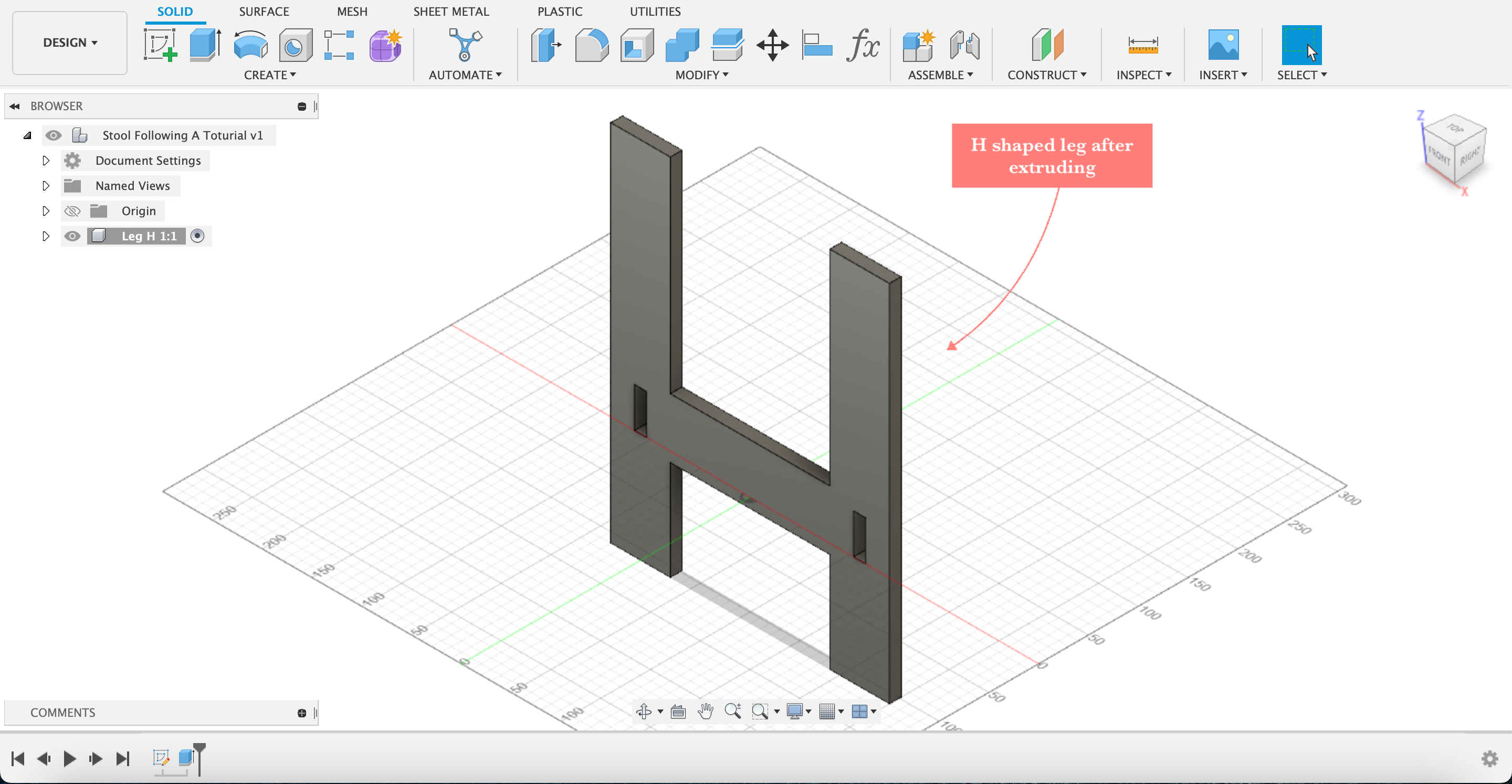
- Step3, extrude the sketch, 12mm which is the plywood thickness
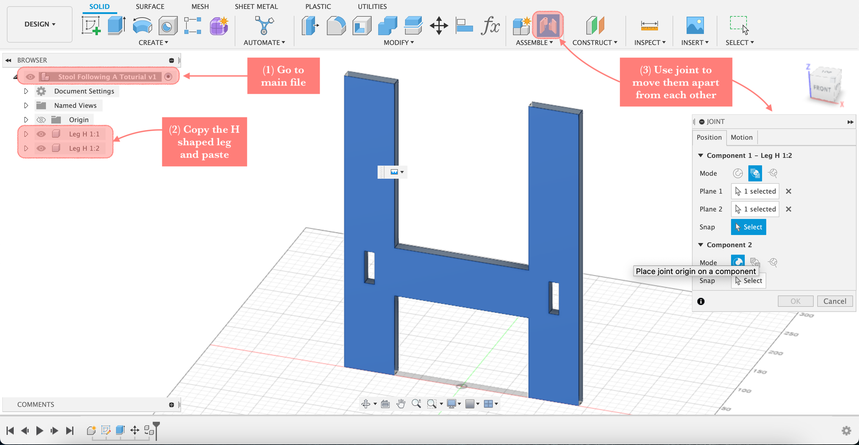
- Step4, go back to the main file and duplicate the H shaped leg, then use joint to move them apart from each other
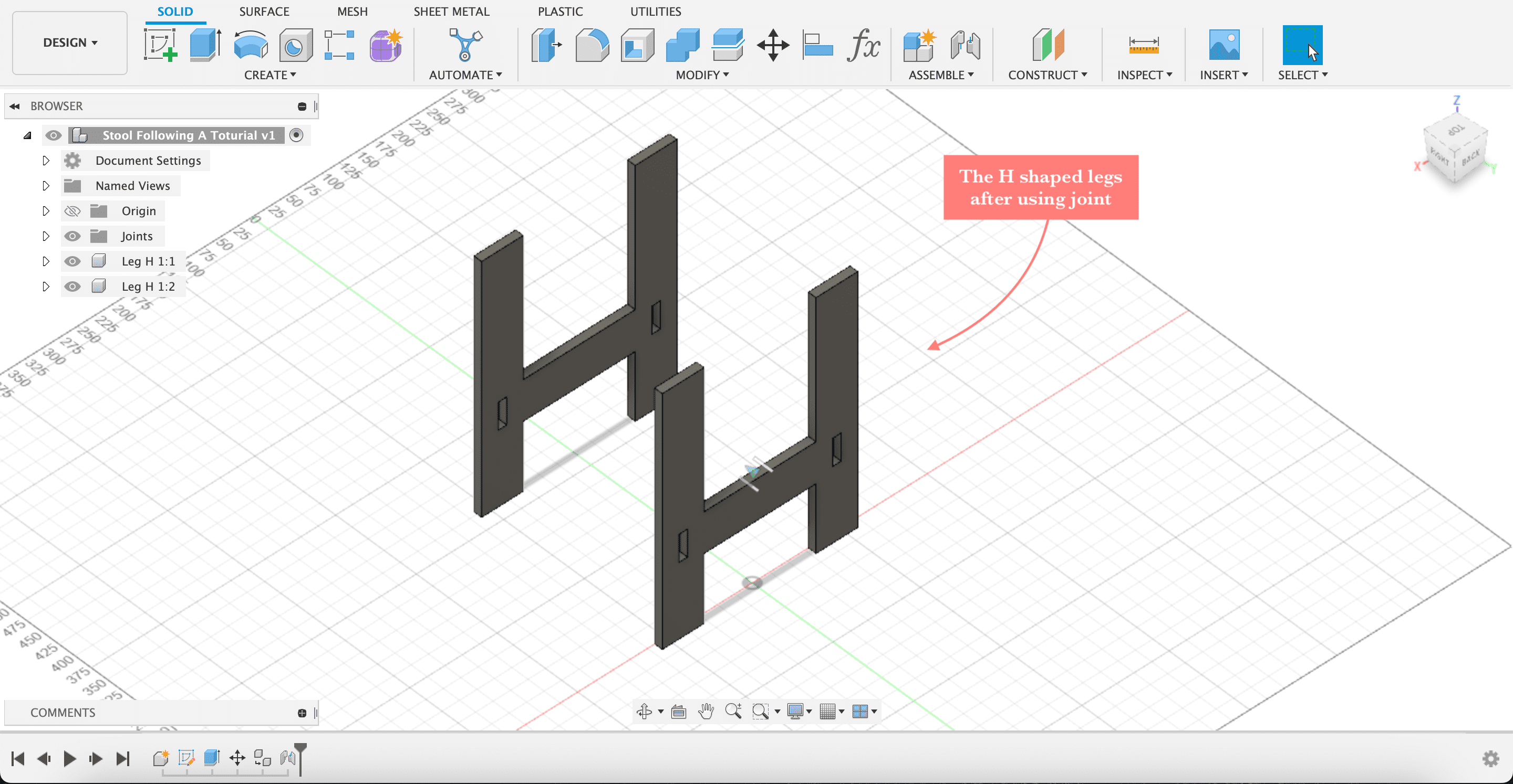
- Step5, this is the H shaped legs after using joint
Creating The Other Leg Parts
- Step6, creating the other leg part; from the main file create a new component, create a sketch using the help of the H shaped leg, and fix the dimensions

- Step7, the leg part after extruding, 12mm

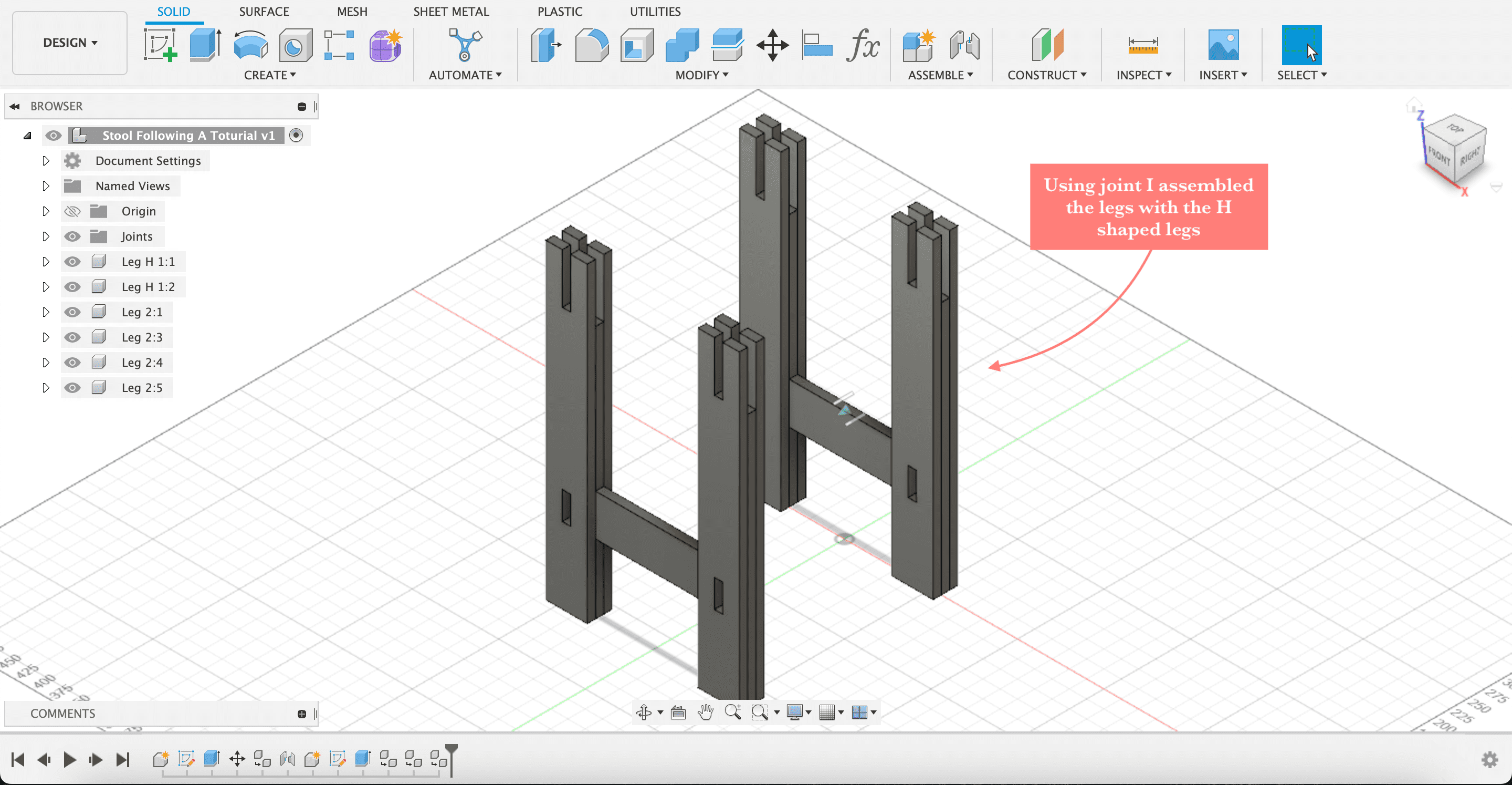
- Step8, using joint assemble the legs with the H shaped legs
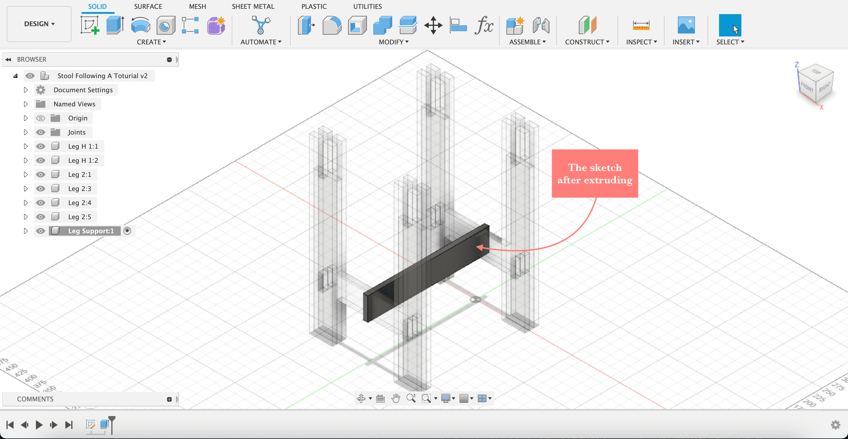
Creating The Leg Support
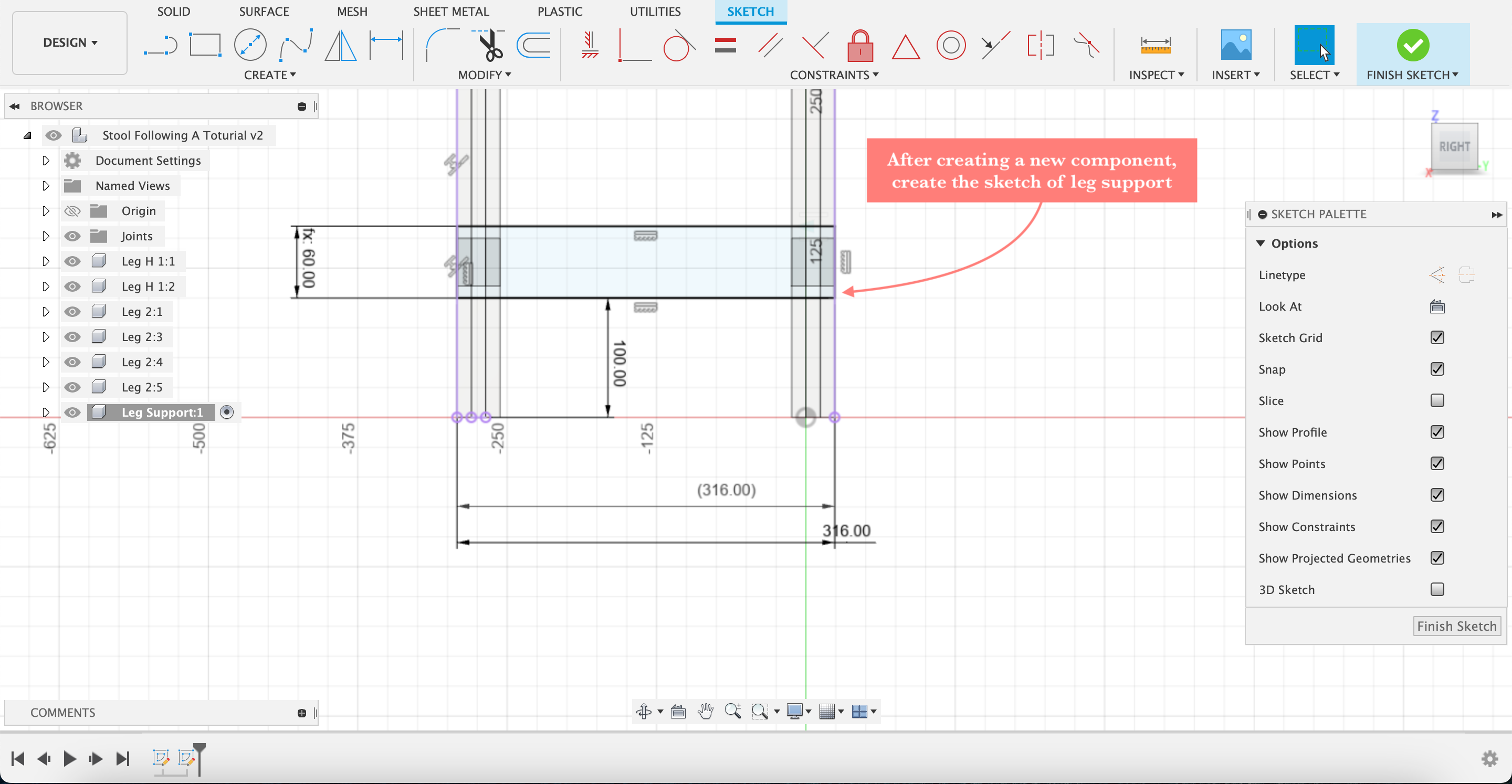
- Step9, creating the leg support; after creating a new component, create a ruff sketch of the leg support
- Step10, extrude the sketch 12mm
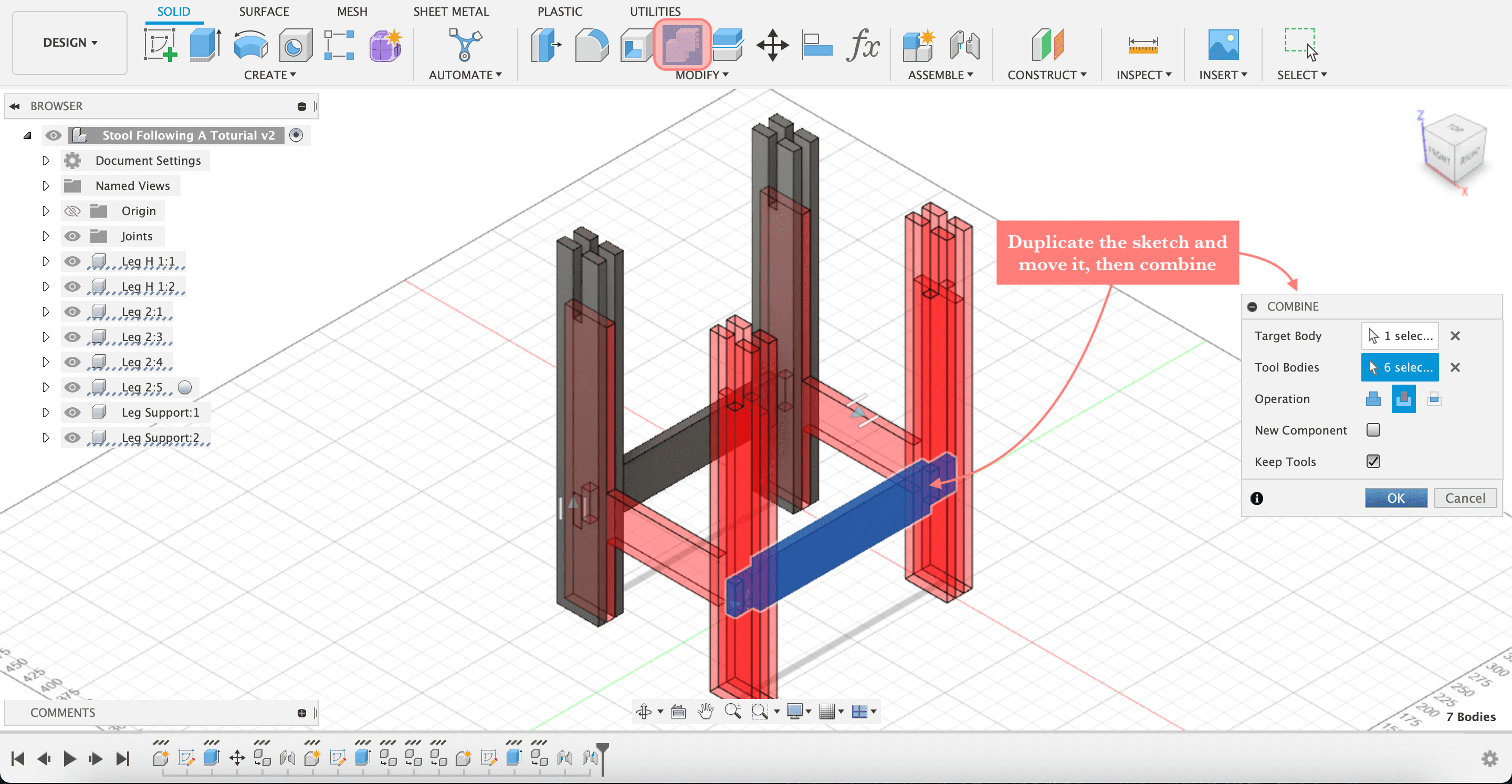
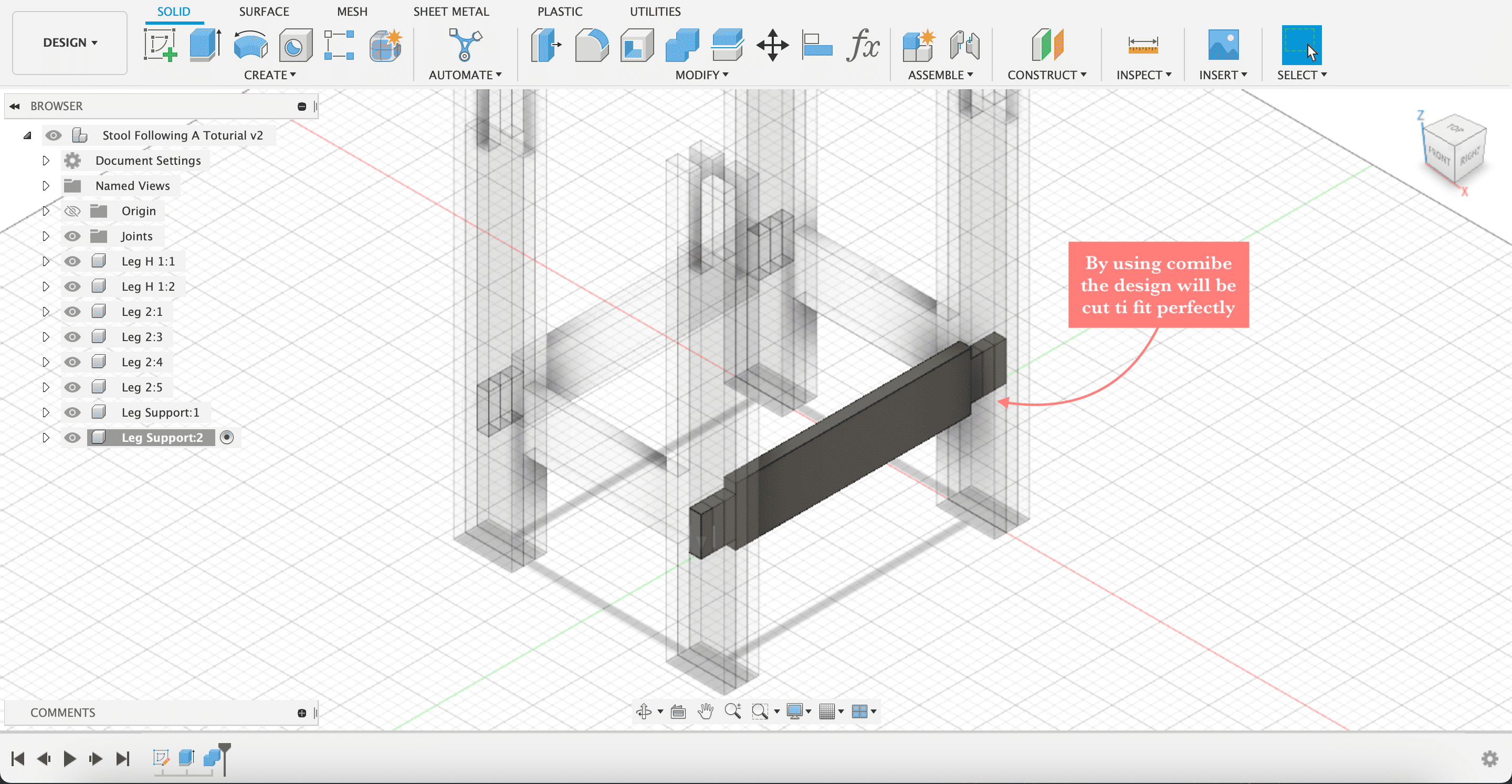
- Step11, duplicate it, then move it to where it fit, after that use combine to cut where the leg part and the leg support interfere
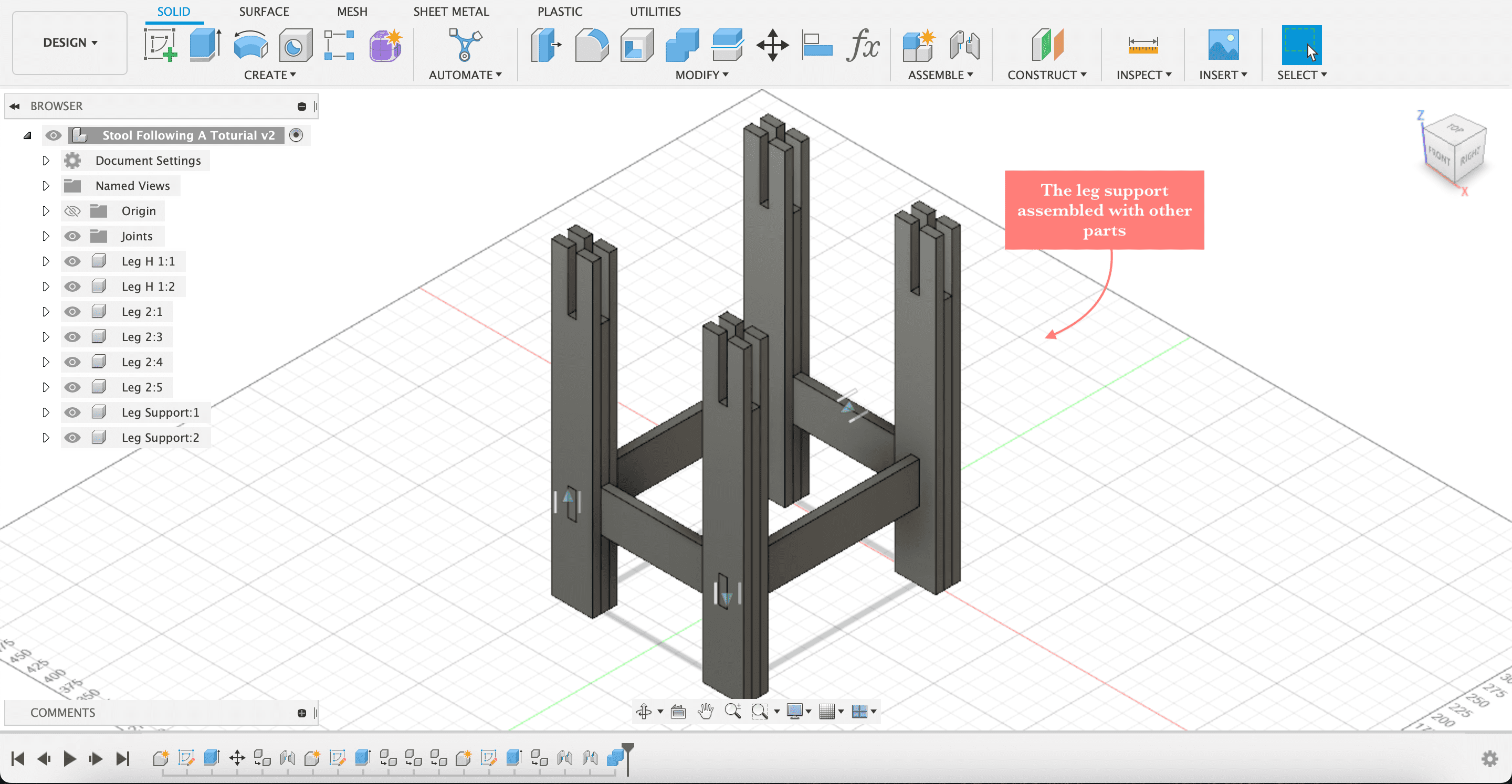
- Step12, assemble the leg support with the other parts
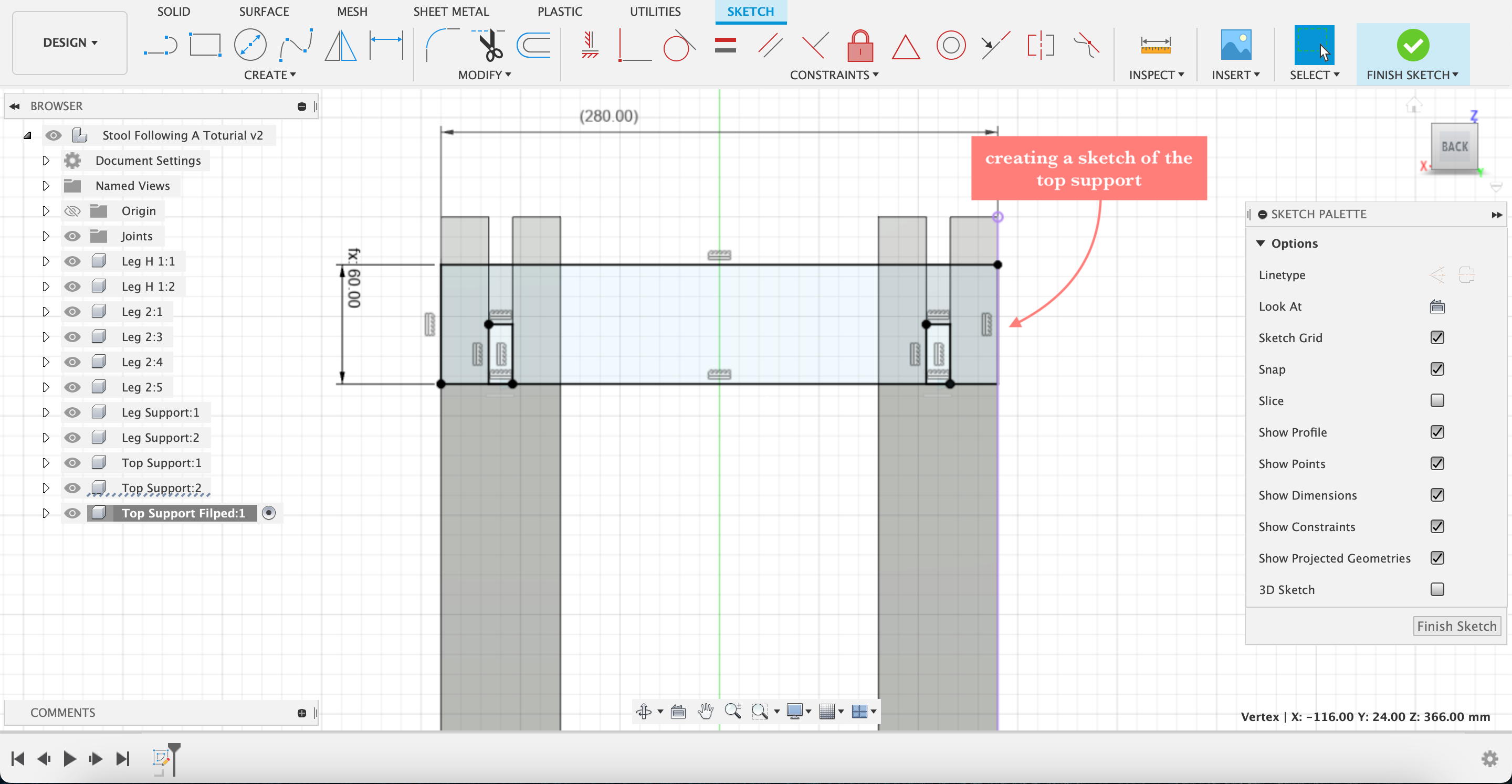
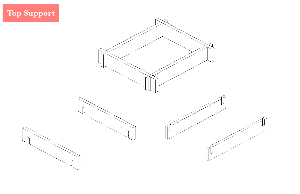
Creating The Top Support
- Step13, creating the top support; create a ruff sketch
- Step14, extrude it 12mm
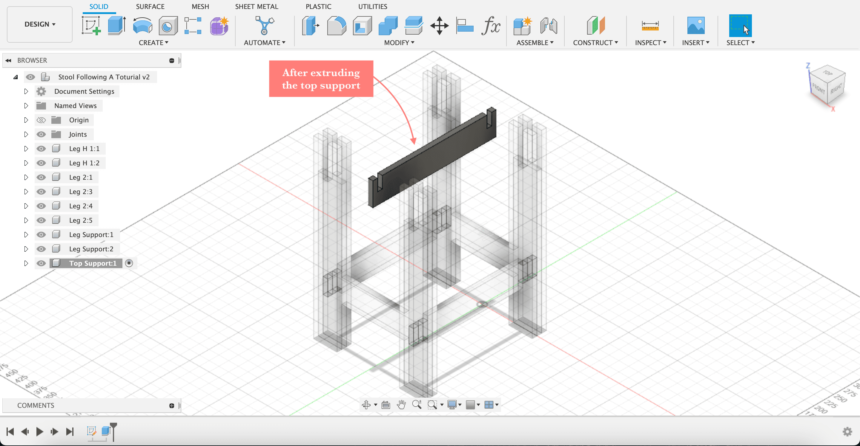
- Step15, duplicate and use joint to assemble them

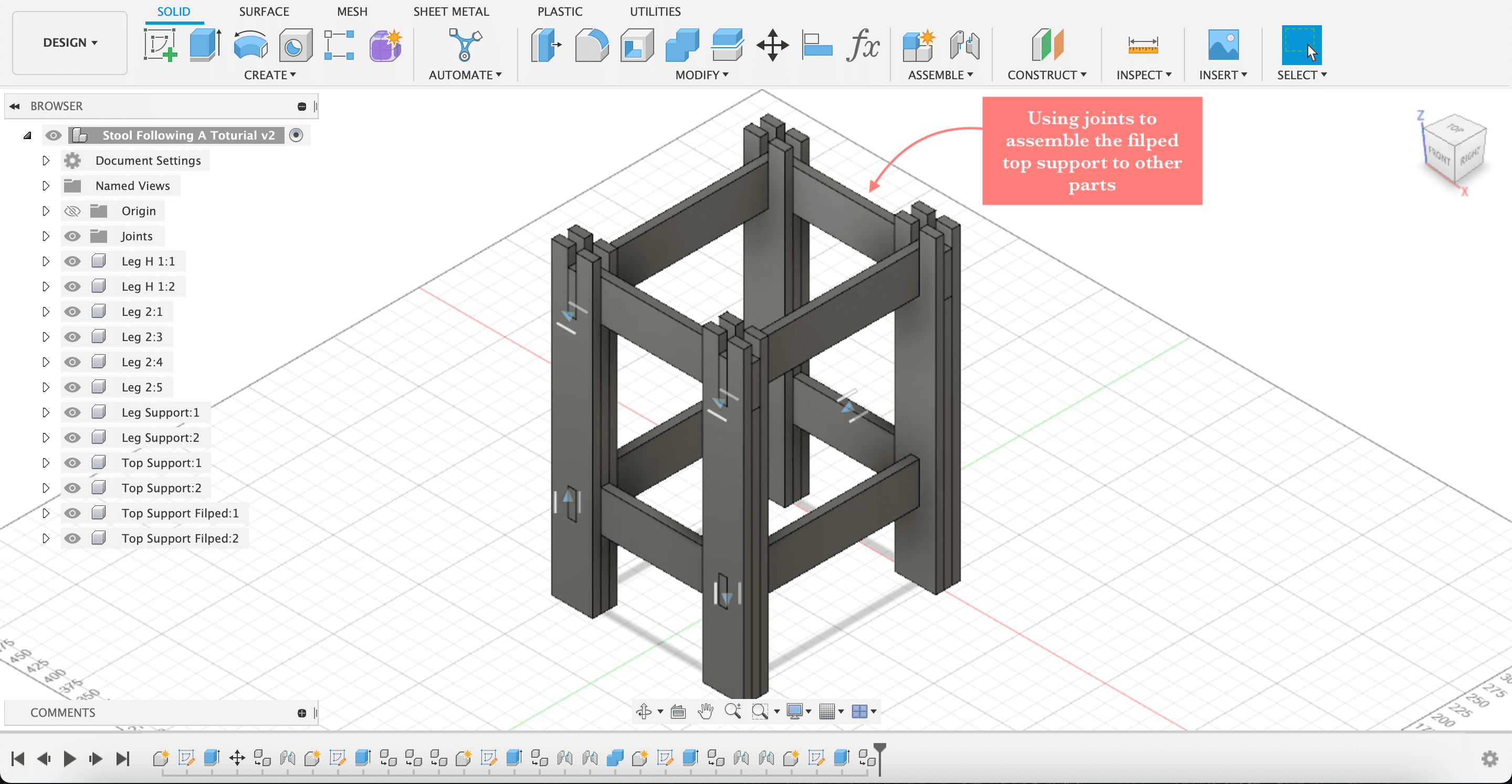
- Step16, now create a sketch of the fliped or upper top support, extrude, duplicate
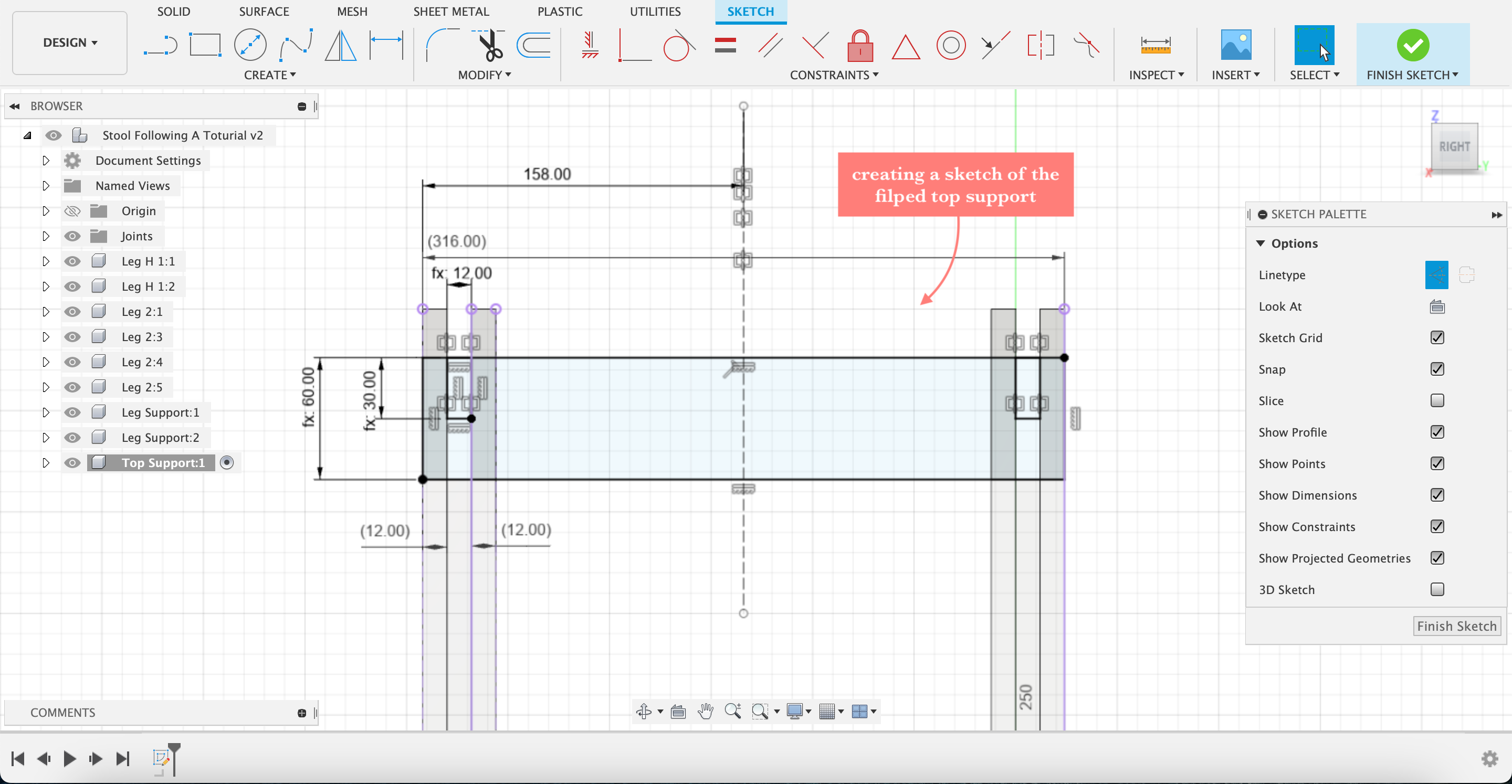
- Step17, again use joint to assemble
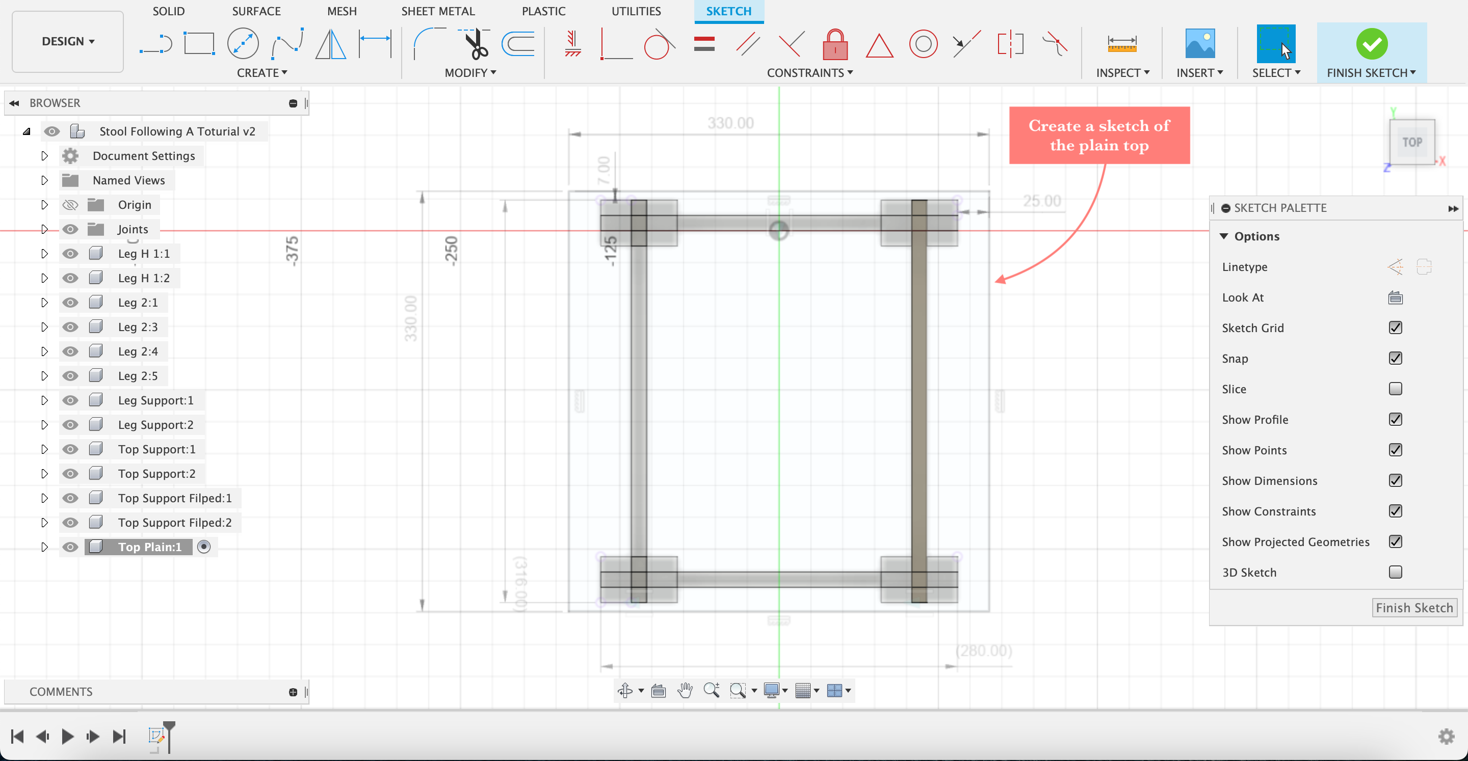
Creating The Plain Top
- Step18, creating the plain top; create a sketch
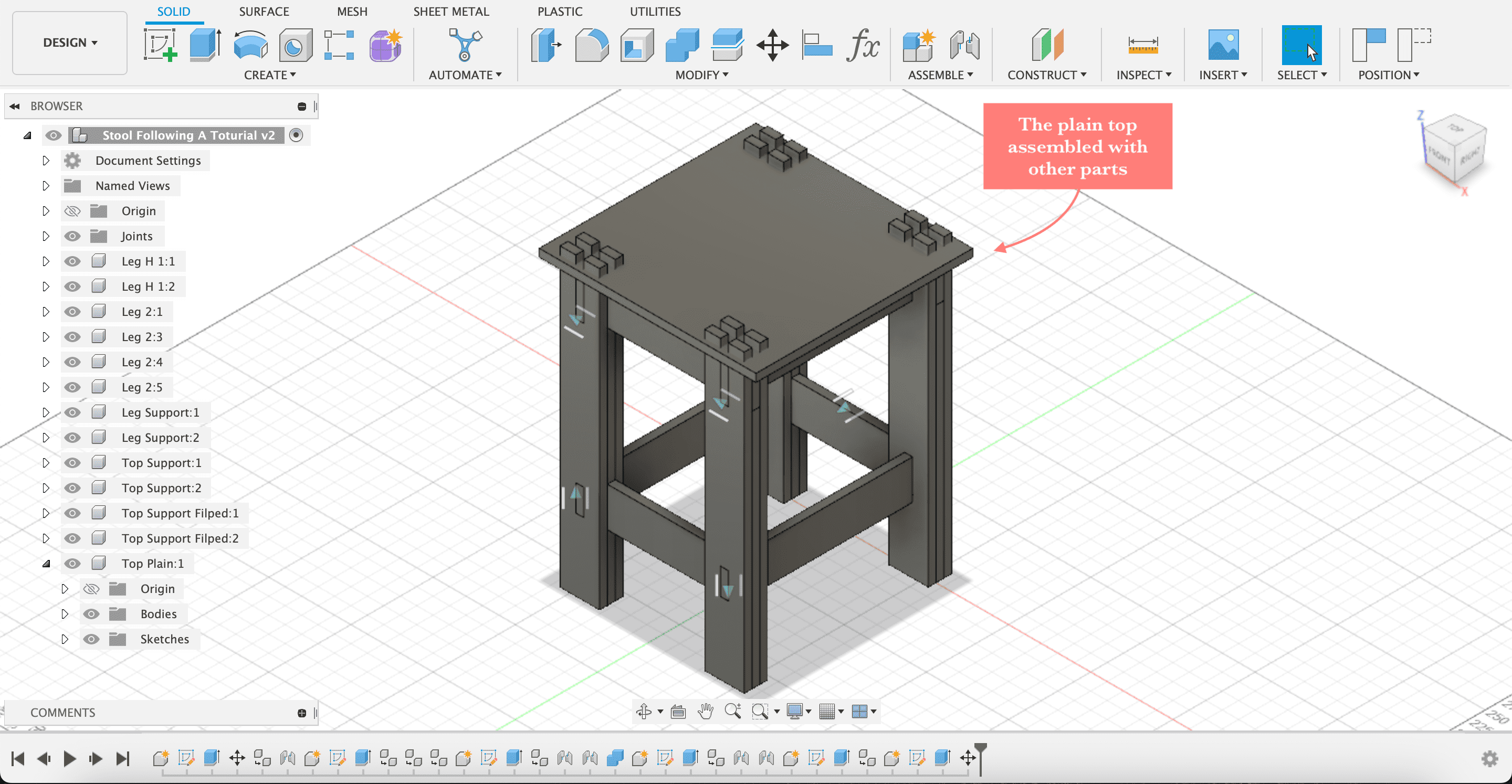
- Step19, after extruding, use move to move the plain top to fit

- Step20, use combine to cut where the plain top and the legs interfere, then it will be assembled with other parts

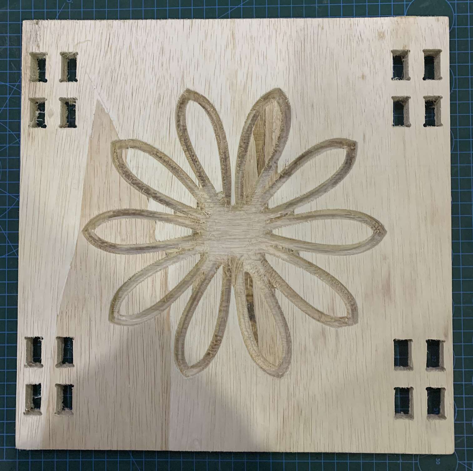
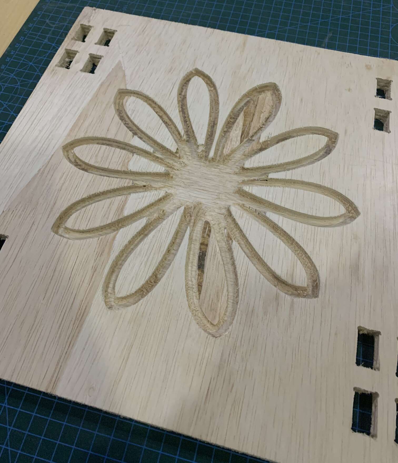
Creating The Flower Top
- Step21, createing flower top; create a sketch, I used a circle, spline, construction line, mirroring, and circular pattern to create the flower shape
- Step22, extrude the sketch up 12mm, the extrude flower design about 5mm down

- Step23, assemble the flower design with other parts

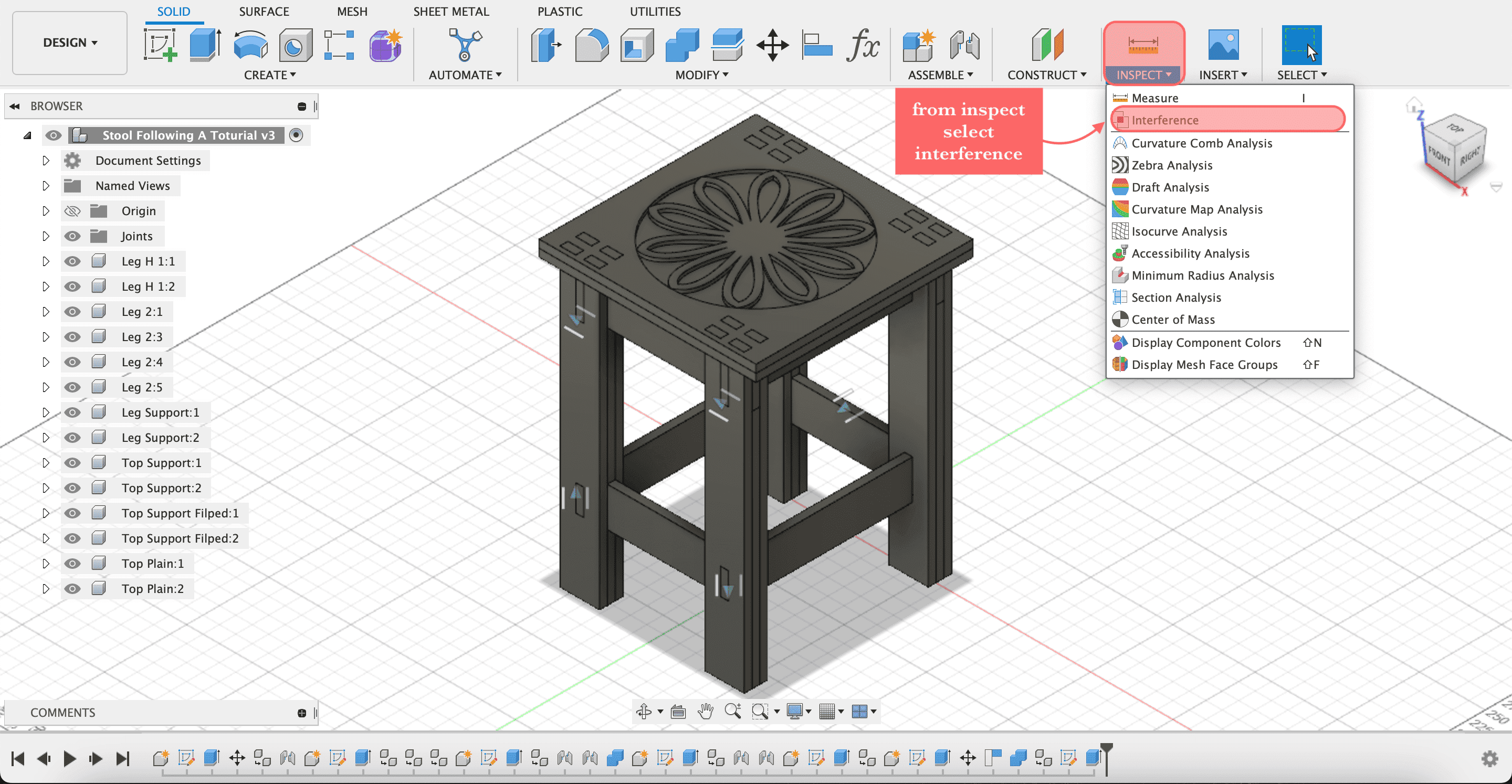
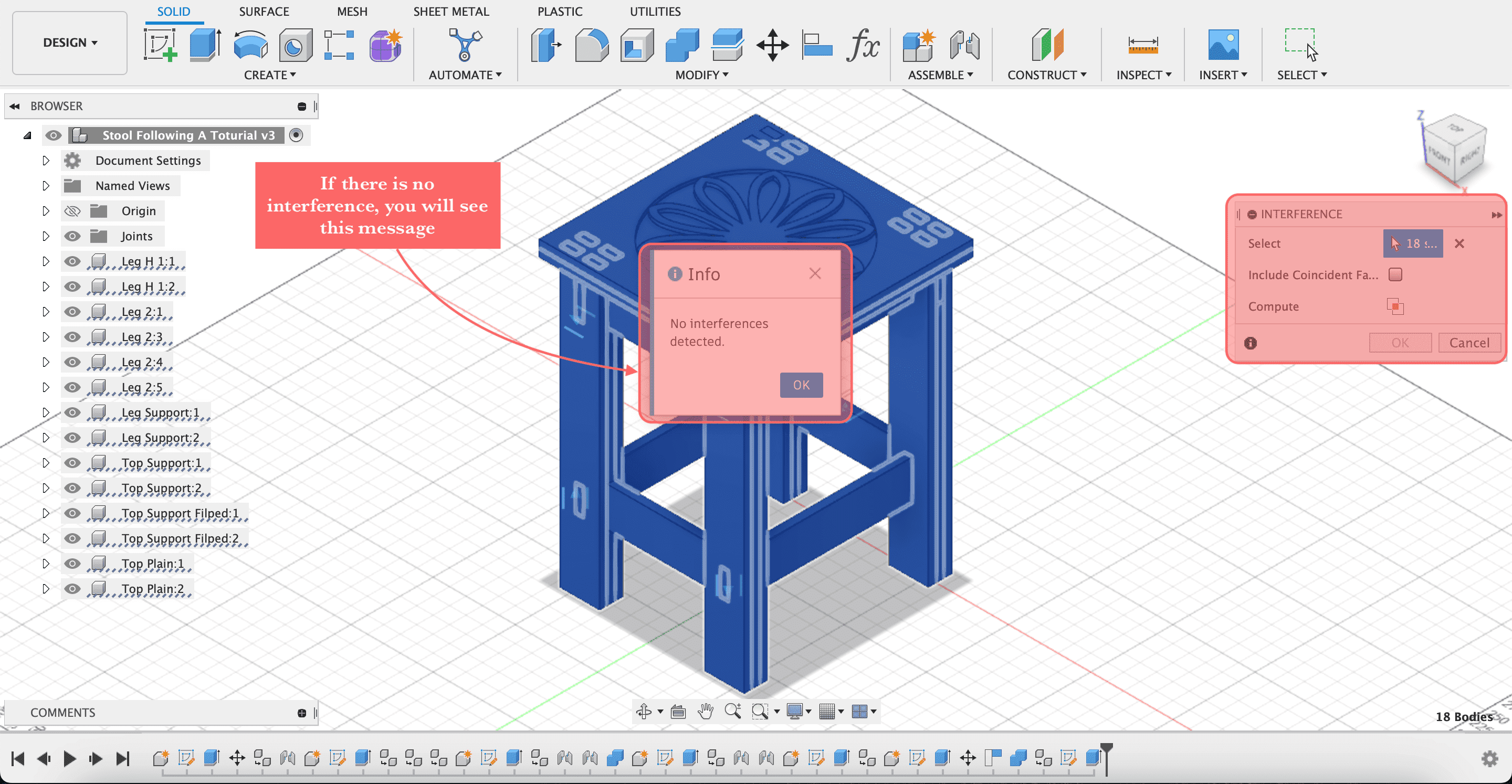
Interference
- Step24, using interference to make sure that there are no part intrefere with each other
- Step25, if there is interference, they will show up
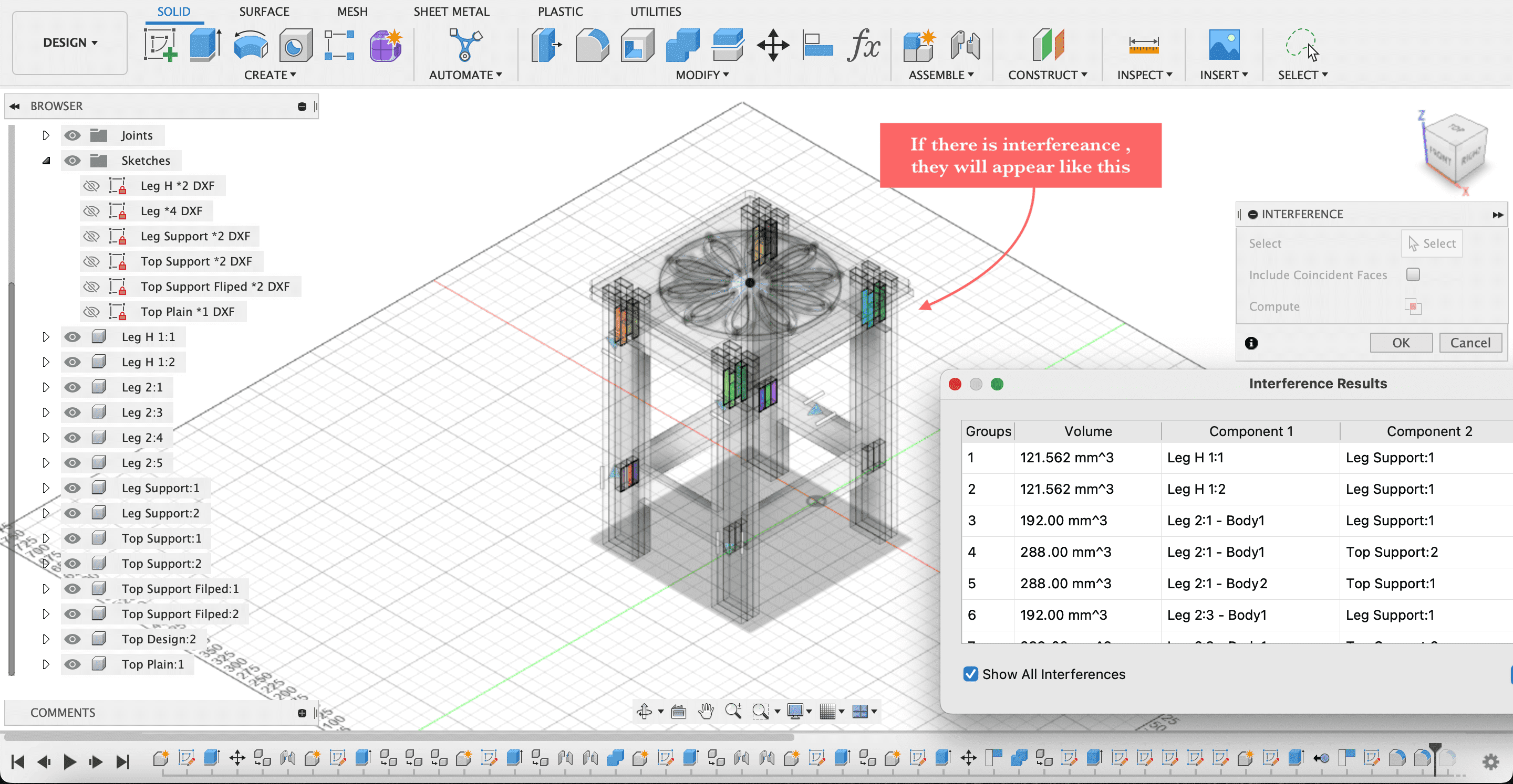
- Step26, if there isn’t any overlap, then perfect!👌🏼
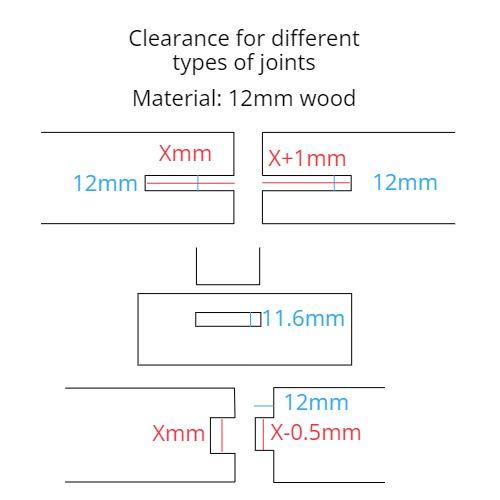
Clearance
- Step27, be careful to include clearance for the joints accordingly, I made the joint openings in my design smaller (was 12 mm made them 11.6 mm)
Save
- Step28, at the end the files need to be saved as DXF, so create a new sketch on top of each part of the design and save as DXF files
The Final Design
At the end of the designing process in Fusion360, this is how it turned out.


You can have a closer look here, and you can also download the Fusion360 file from here.
Using CNC Machine To Cut The Design
The CNC machine is a computer-controlled cutting device. The machine has a power tool router attached, which controls the cutting’s X and Y coordinates. A CNC router can only operate when it is connected to a computer running software that controls the machine’s tool path. CNC stands for computer numerical control. For diverse cutting outcomes, different-shaped and -sized router bits are used. CNC routers can be used to cut materials like wood, foam, and plastics, although most hobbyists carve wood using them.
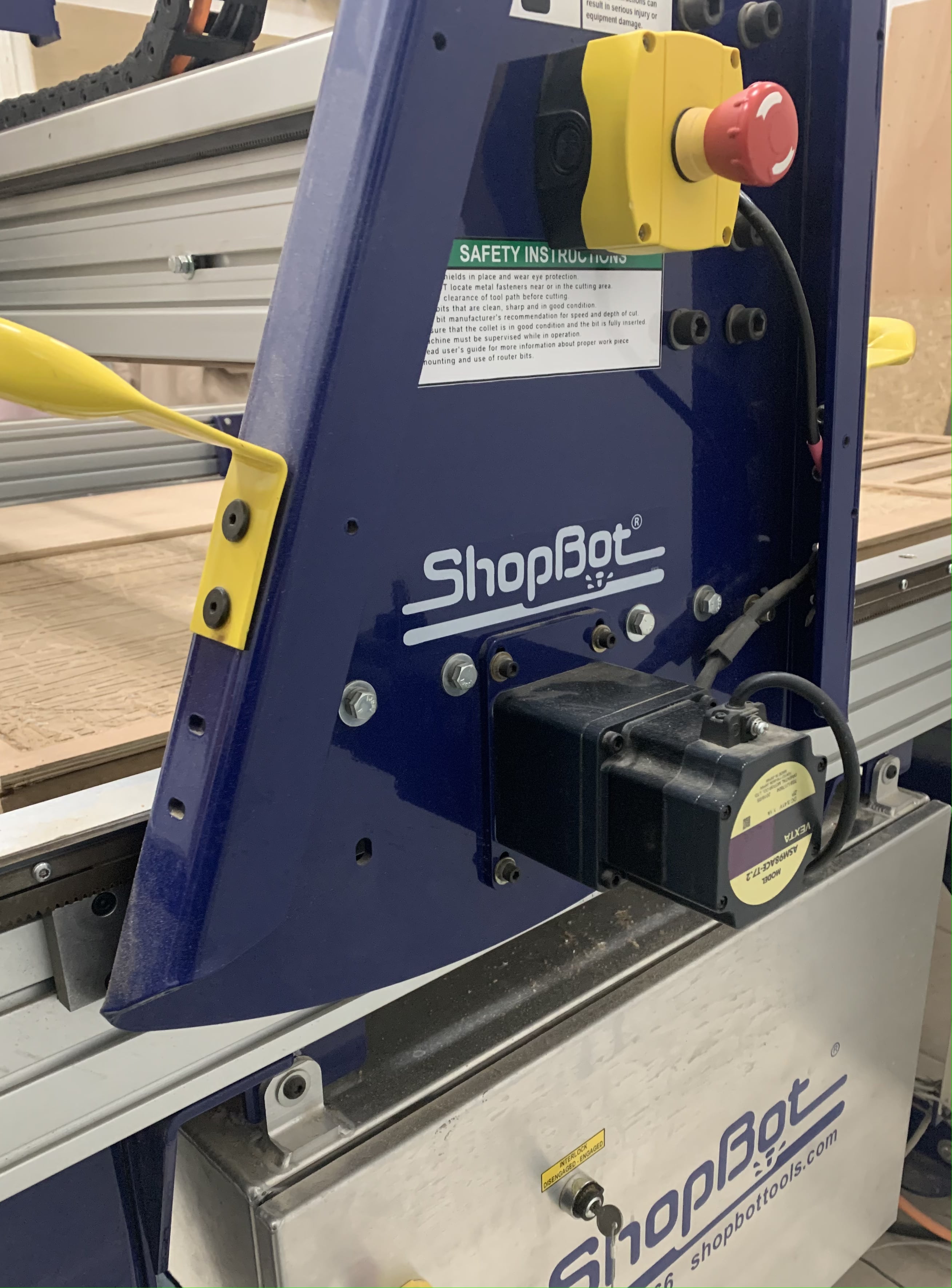
The machine we have in Fab Lab is ShopBot CNC machine and it is so big, it takes a whole room. This is how it looks.
Before using the machine, we have to know about safety.
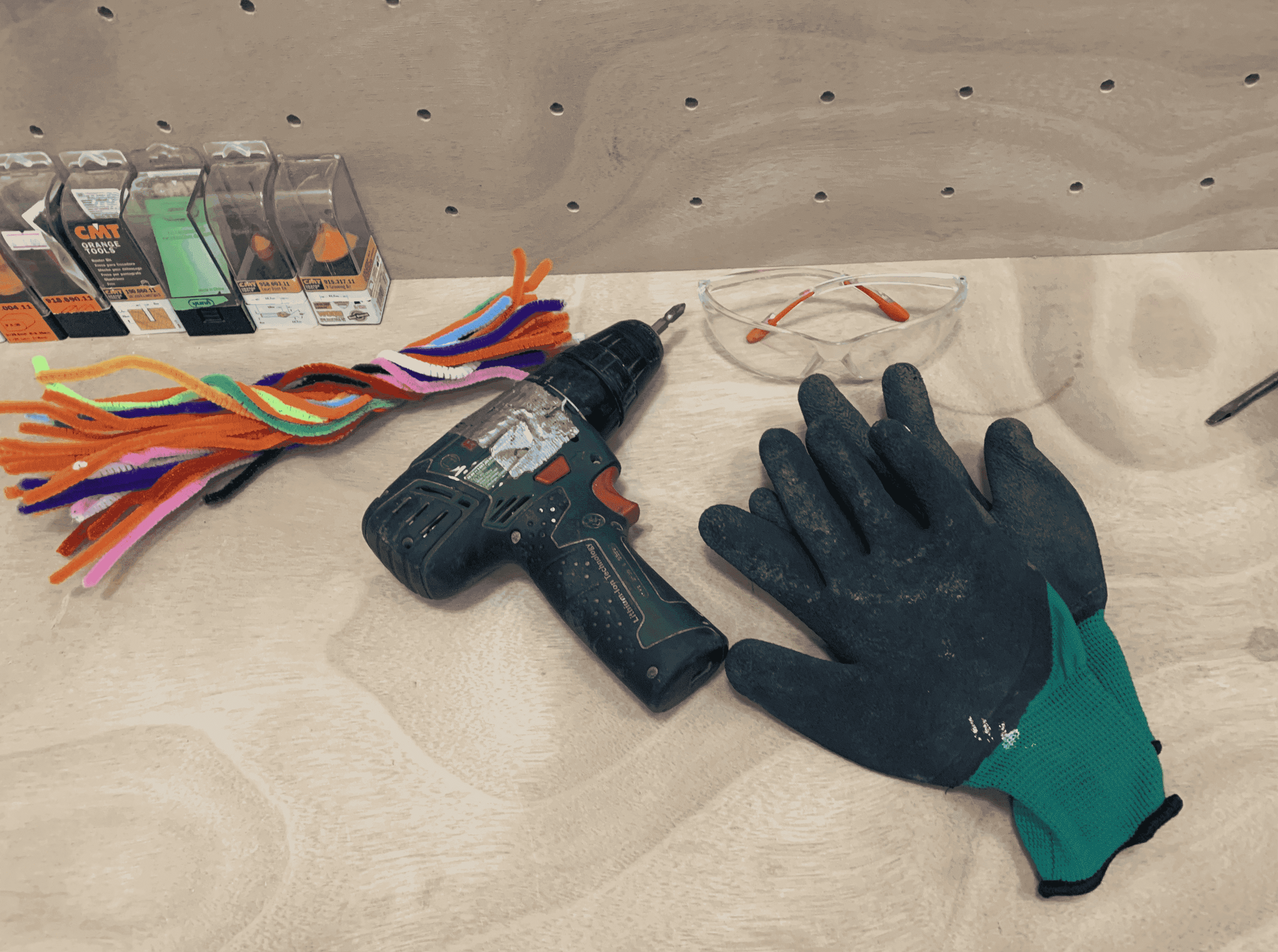
The dress code for your safety should be accordingly:
- Wear closed toed shoes for all cutting sessions. If you have safety shoes it is recommend to wear them.
- Avoid wearing loose arm clothing and dangling jewelry and keep long hair tied and hijab tucked in.
- Always wear saftey glasses.
- Wear gloves.
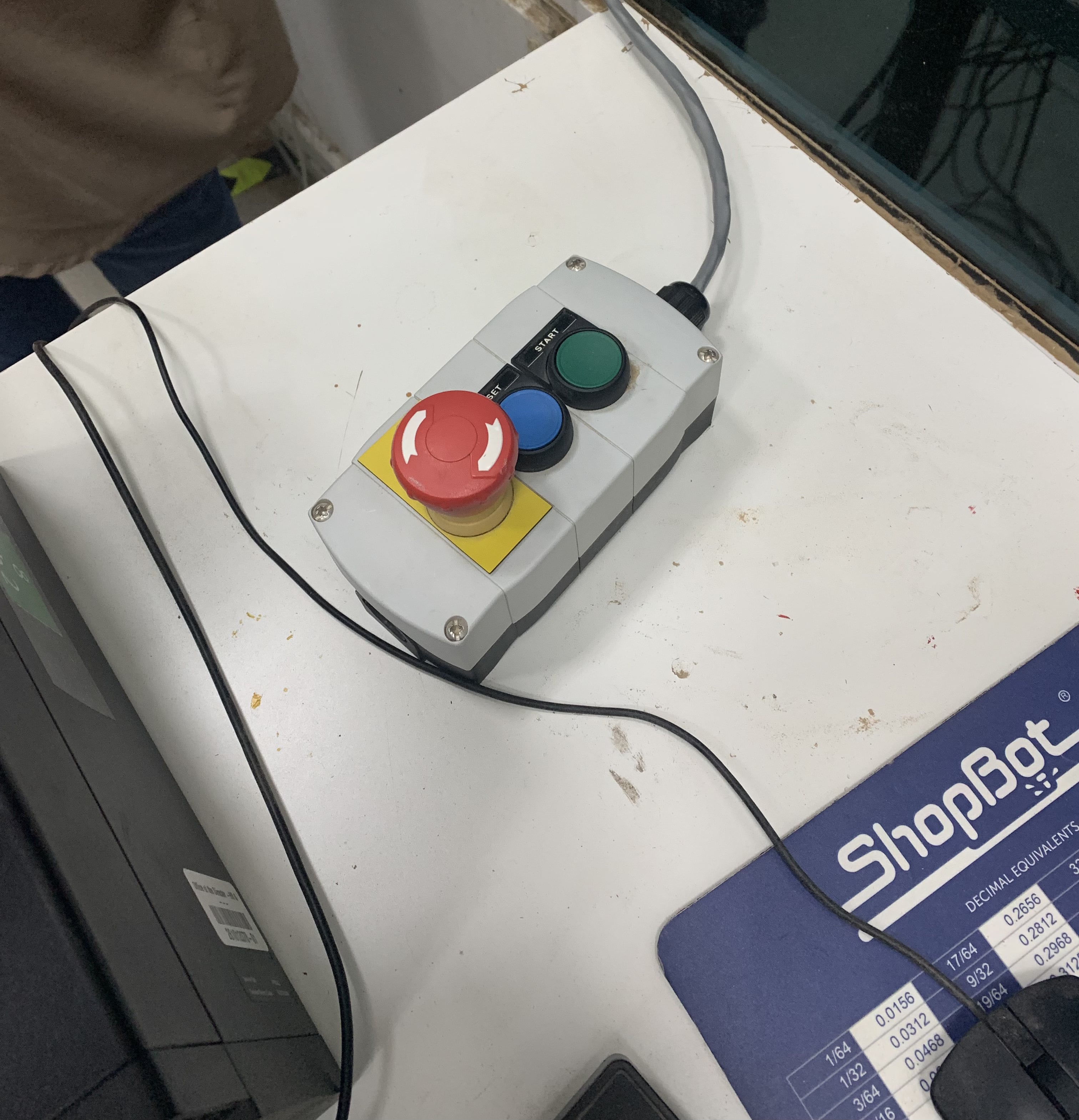
In case of an emergencey, to make the machine shutdown completely push the emergngy botton. There are two emergngy bottons, one located on the side of the machine, and the other one is near the computer. Also, you can click on any thing on the computer keyboard the machine will stop.
Using The CNC Machine
The CNC machine can only operate when it is connected to a computer running software that controls the machine’s tool path, and that software is Vcarve. You can download the program from here, to test the tool path for you design. However, the paied version downloaded on the computer attached to CNC machine is where you will do the actual tool path.
So, after I finished my design I sent the DXF files to fablabbh.share@gmail.com to be opened on the computer connected to the CNC machine.
1. Step1, open the DXF files in the software
2. Step2, you should add fillets specially at joints; there are multiple type of fillets including: Dog Bone Fillet 🦴 these fillets are used for creating clearance in internal corners to allow slotted pieces to fit togather. T Bone Fillet these fillets are used for creating clearance in internal corners when the slot is the same size as the tool. And there are more fillet types. I used T bone fillet with a radius of 1.5mm

3. Step3, we did 3 different tool paths: One as a pocket to engrave the flower shape, Two to cut the joints from the inside, and Three to cut the rest from the outside
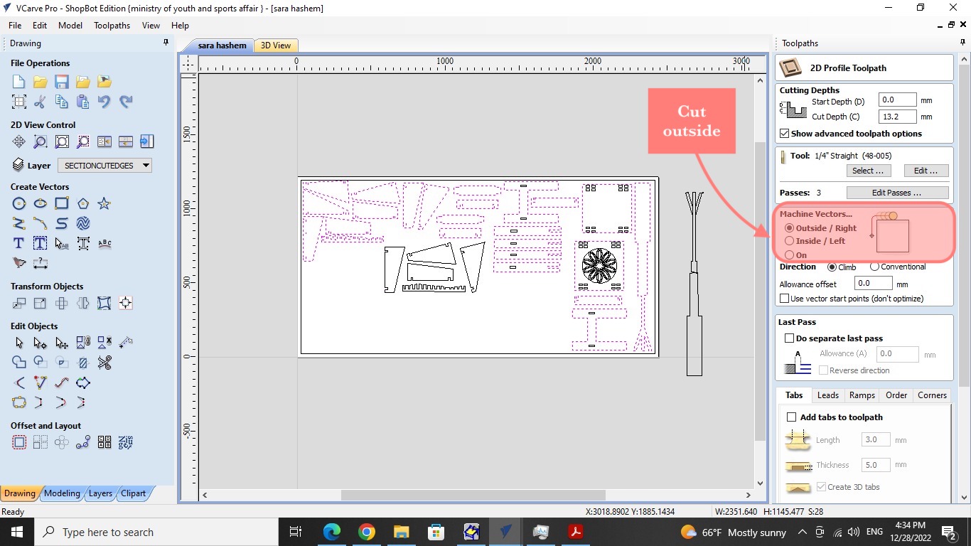
4. Step4, make the number of passes 3

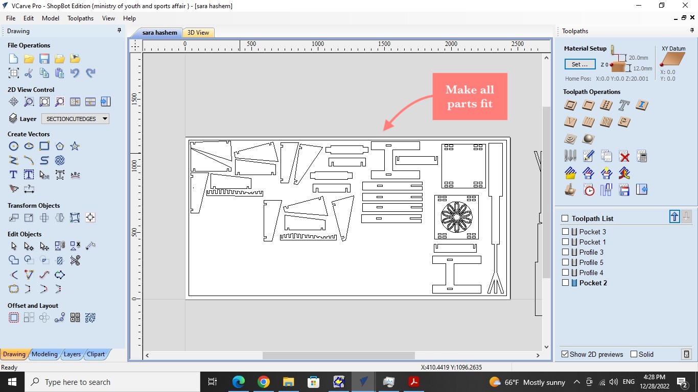
5. Step5, make all the items fit togather on the sheet, I selected each object alone and noticed that the lines were not connected. I used the join open vectors tool and the value 0.000 to close the gaps and create a single object.
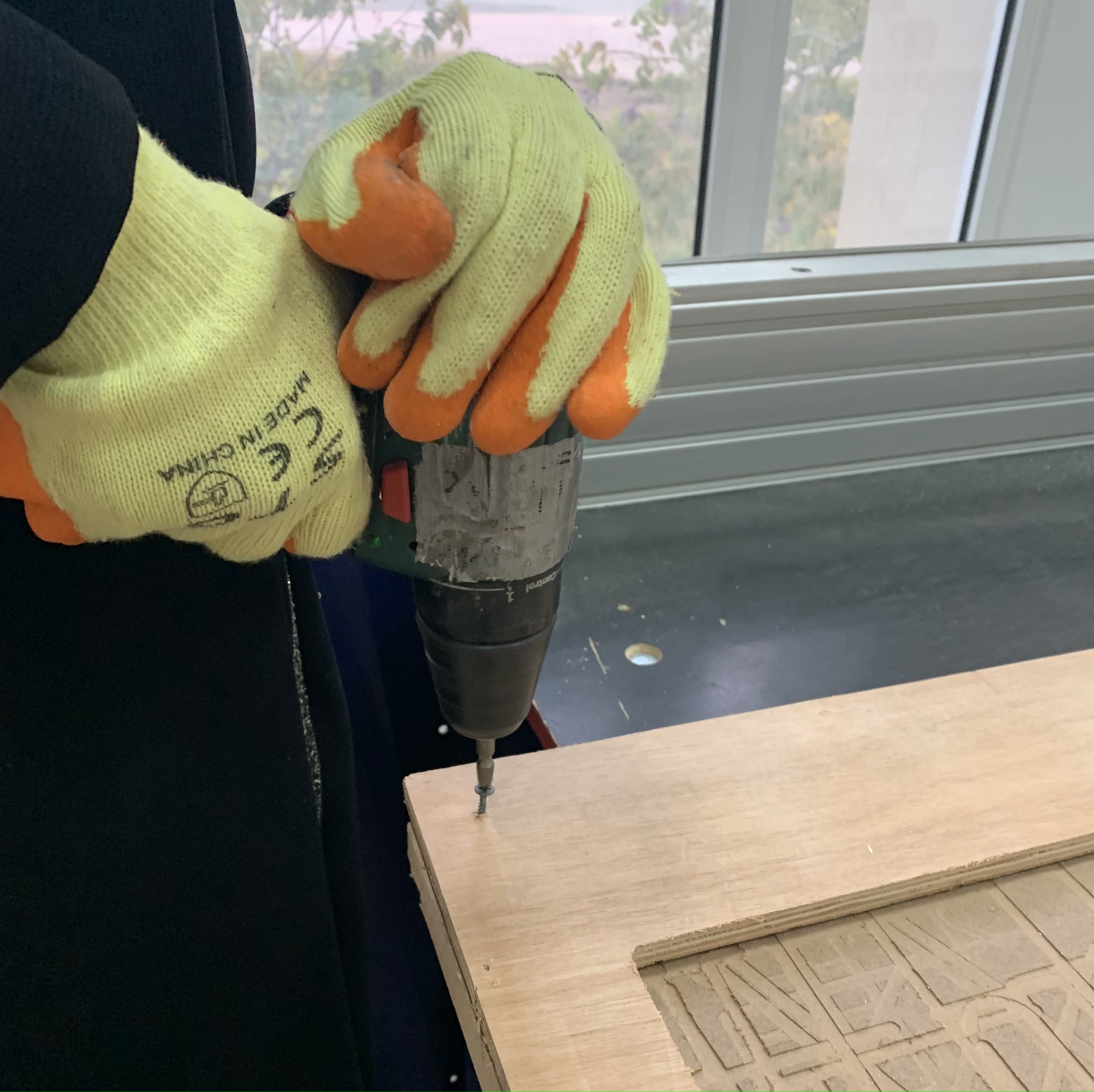
6. Step6, fix the material on the machine bed using screws where needed so the playwood doesn’t move
7. Step7, set up and start the router

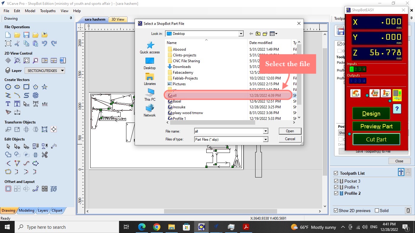
8. Step8, select the file again, Click preview toolpath and play button to display the cutting process and make sure it’s correct, Click the save toolpath button after making sure all toolpaths are chosen, file
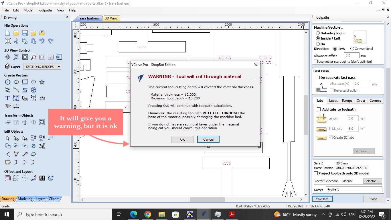
9. Step9, you will recive a warning because the cutting depth is more than the material depth, however this doesn’t matter because we have a MDF sacrifice sheet under the plywood we will cut
10. zero axies and z calibrate the machine
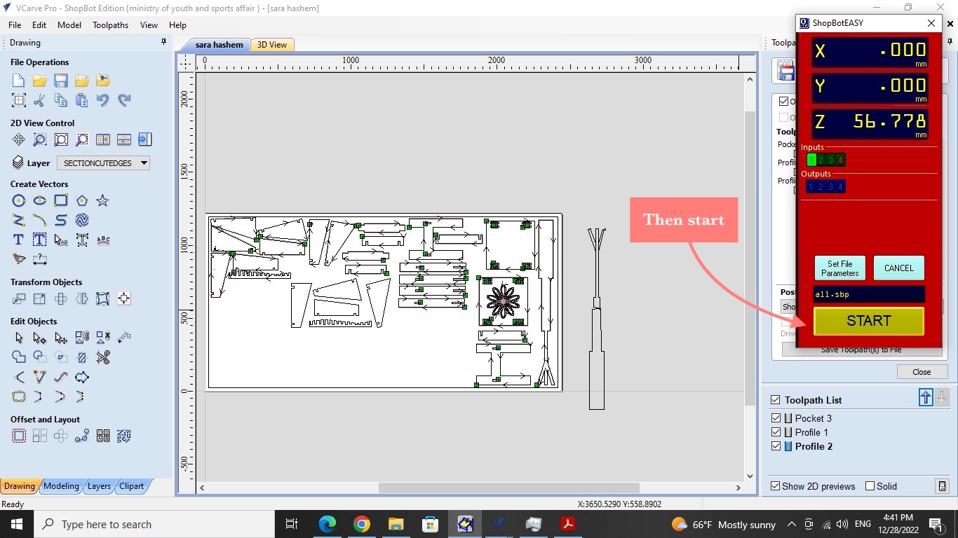
10. Step10, finally, turn on the vacuume, from the computer click cut parts, choose your file and hit start, hold the start green button for couple of seconds, you will start the spindle and start to cut, the software will show the percentage of progress
Wood Finshing Procedure & Assembling
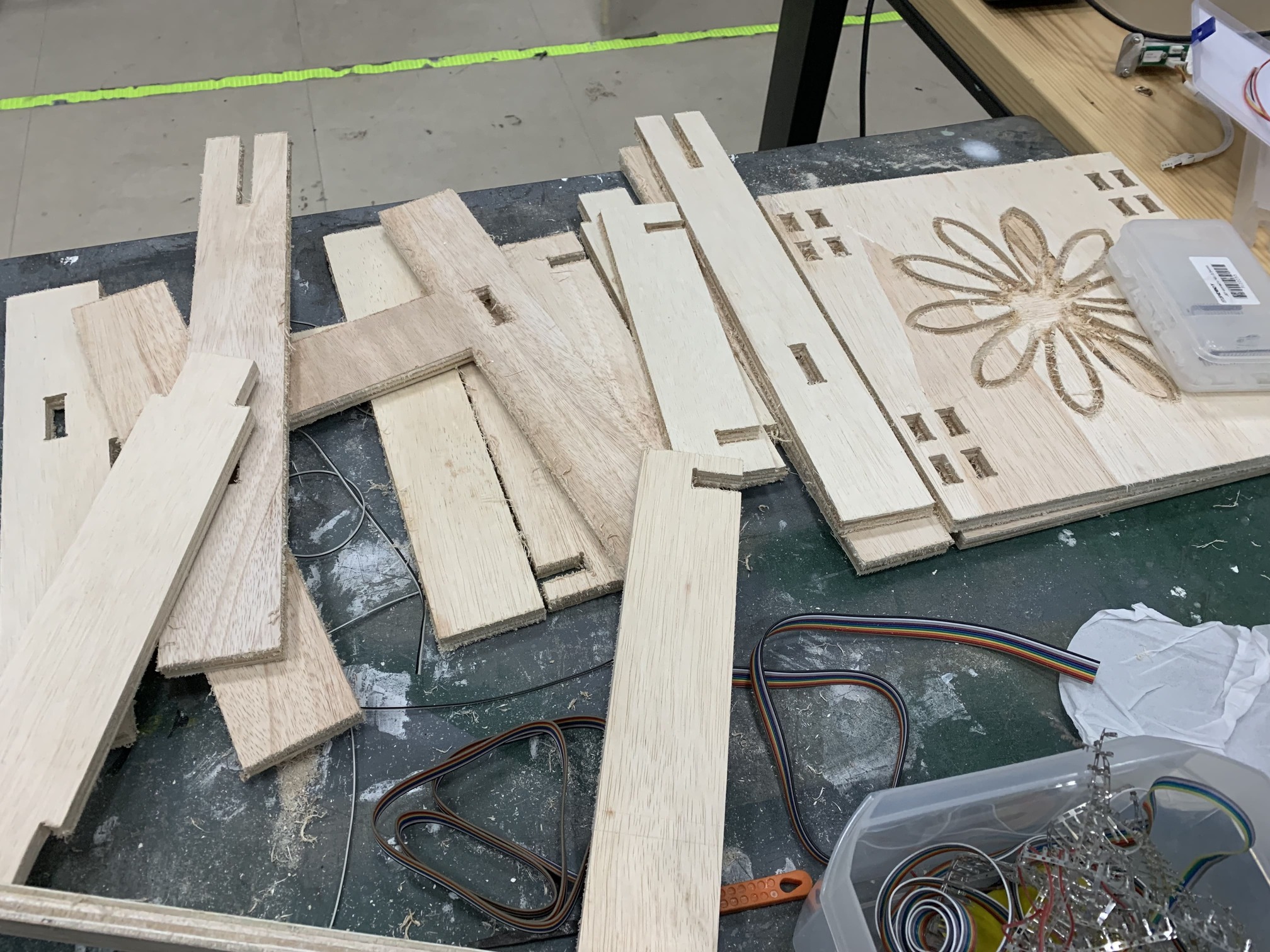
These are all the pieces right after the machine had cut them.
I immediately wanted to test if the joints will work together or not, so I started by sanding and filing the joints and they worked! 👏🏻

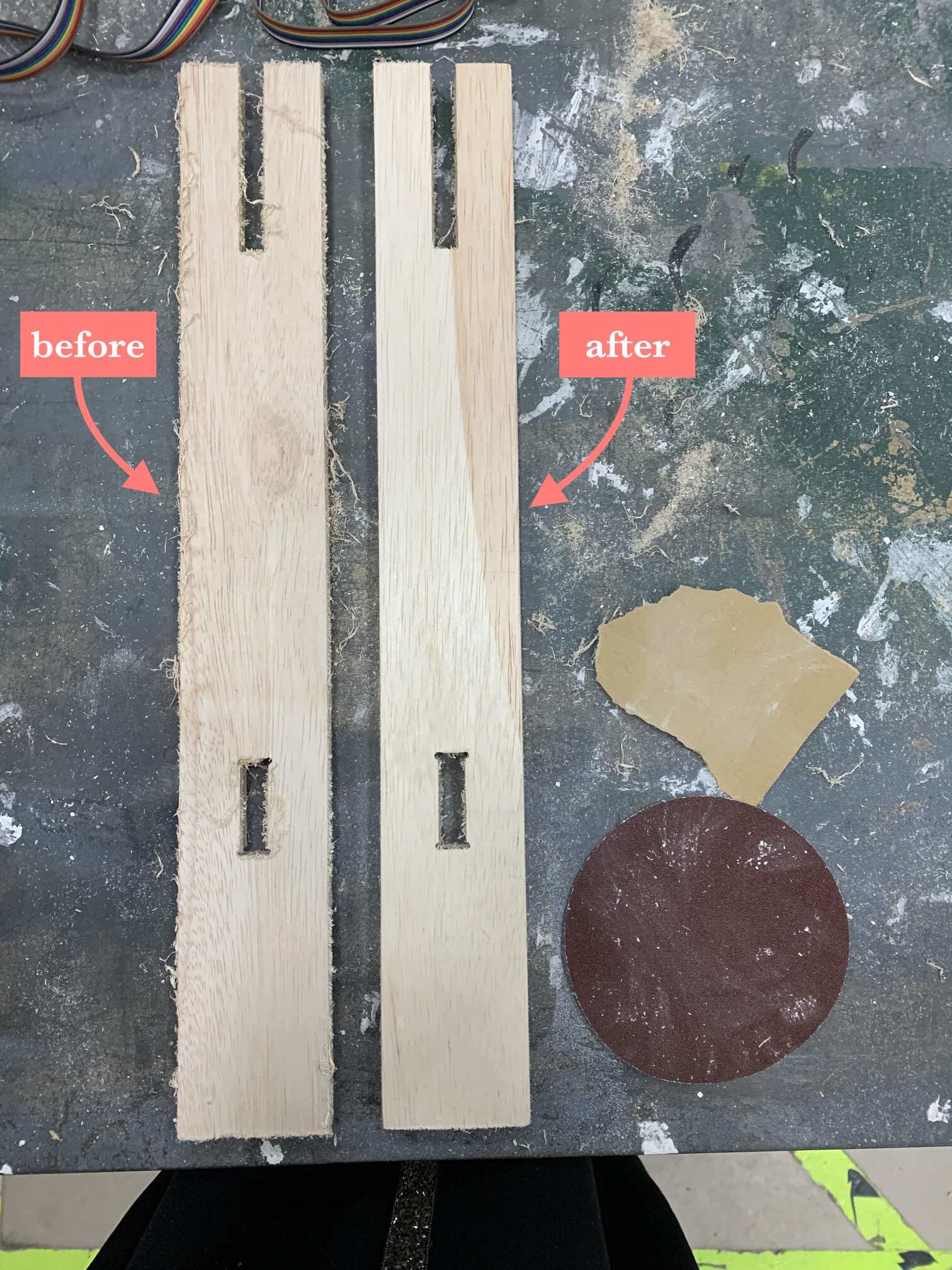
The cut edges of the pieces are a bit ruff, I used sanding paper to sand the edges. While doing this procedure make sure to wear a mask, safety glasses, and gloves as personal protective equipment.
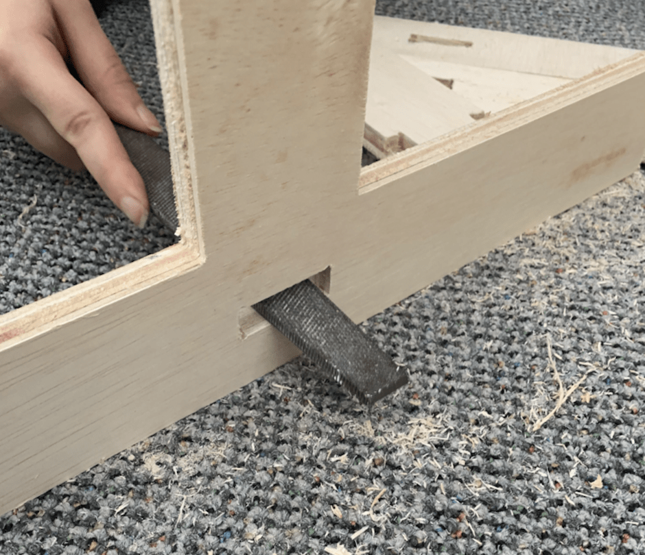
Becouse I added clearance (making the opening 11.6mm instead of 12 mm) the joints were kind of small, so I used a file to widen the joint openings.
After sanding all the pieces and filing all the joints, I connected the joints togather using a rubber mallet that would not cause any harm to the wood.
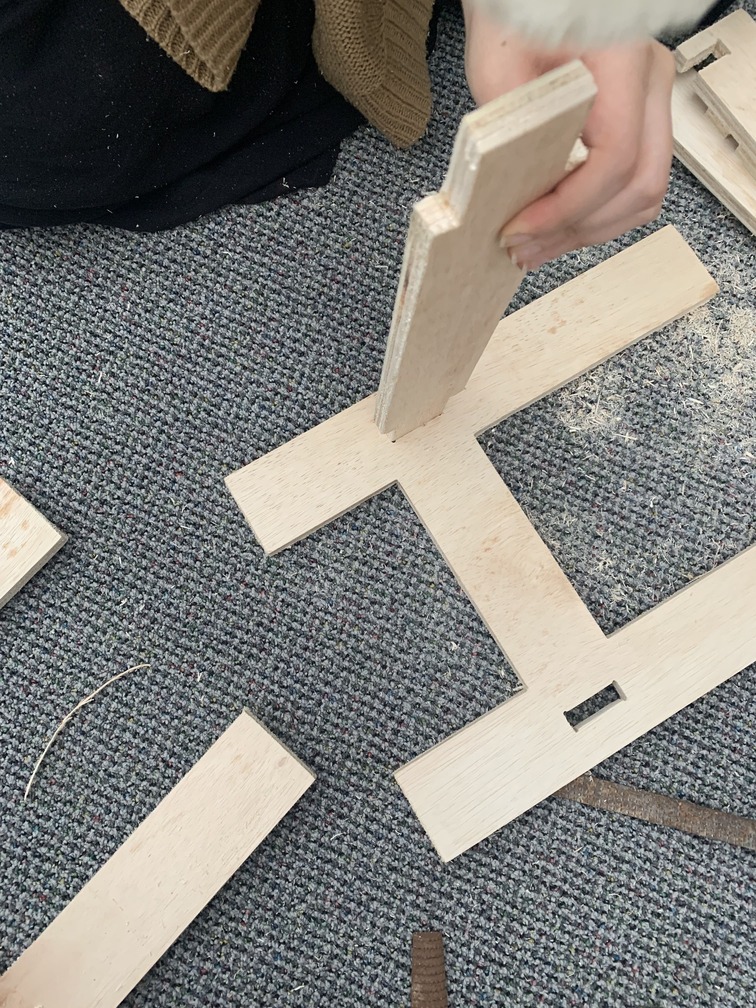
Putting it togather! Except the flower top.

Putting it togather!
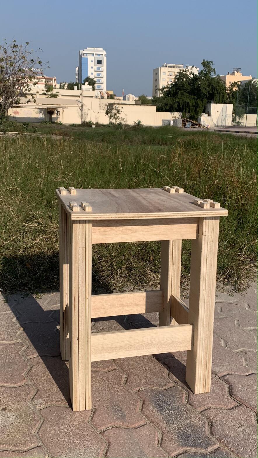
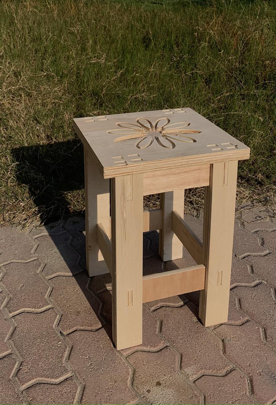
Putting it togather! With the flower top.

The final result!
Problems Faced
Problems:
- During the cutting procedure, some parts of the flower design were cut off and we accidentally got rid of them.
- Also, due to the flower design on top sitting on the stool would not be comftrable.
- Another flaw in the design is that the corners of the top are not rounded. However, I will sand them down to make them more round.
Solutions Sugessted:
- I can laser cut thin wood and glue it on, for the missing parts
- To solve the problem, I can laser cut clear acrylic to fit the border of the flower design. To be honest, I thought for once to just flip the flower top and give up on it working, however I think the feature that makes the stool is the flower, so I am determined to make it work.
- To make the corners more rounded; I can sand it down a little bit. I will not give it the same effect as if it was already cut rounded using the CNC, however at least it is rounded.
Summary

Design Files
Here is the original design files:
- DXF file of H shaped Leg
- DXF file of Leg
- DXF file of Leg Support
- DXF file of Top Support 1
- DXF file of Top Support 2
- DXF file of The Plain Top
- DXF file of The Flower Top
- More of My Sketches 📝
- Summary PDF