8. Input & Output Device
This week I worked on making an input & output device where I measure something by adding a sensor to a microcontroller board and read it, and adding an output device to the microcontroller board and program it to do something.
So this for my output I used LED strip light, and for my input I used temperature & humidity sensor. The sensor should read the temperature and humidity and if the temperature is cold the LED light should turn blue, and if the temperature is hot the LED strip light should turn red.
Output: LED Strip Light
The Hardware
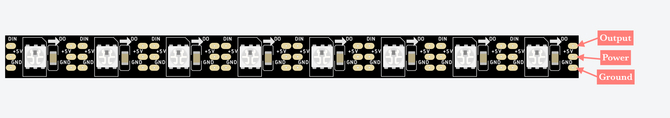
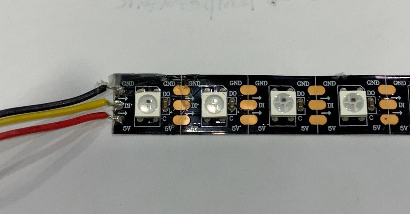
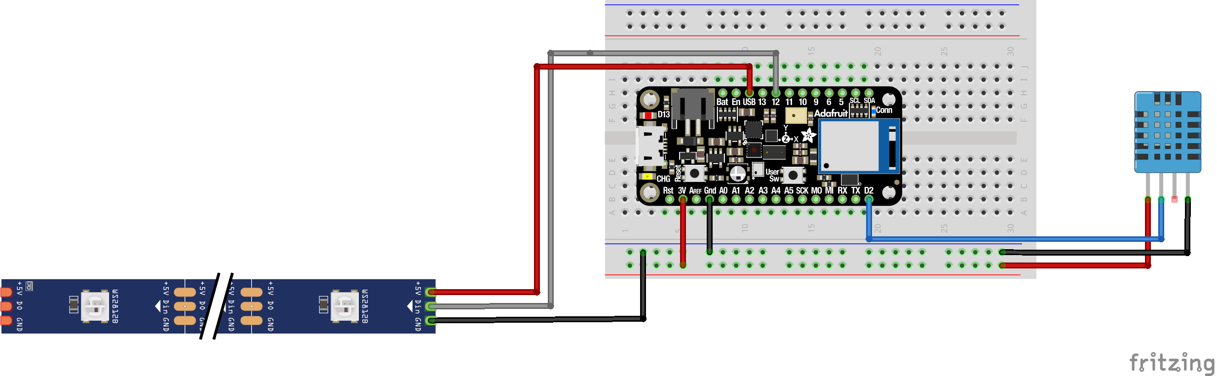
The LED strip lights has 3 connection points and they are;
- The output; should be connected to the data pin you selected in the code
- The power (5V); should be connected to either USB or batteries, in this case, it was connected to the USB pin
- The ground ; should be connected to the negative side
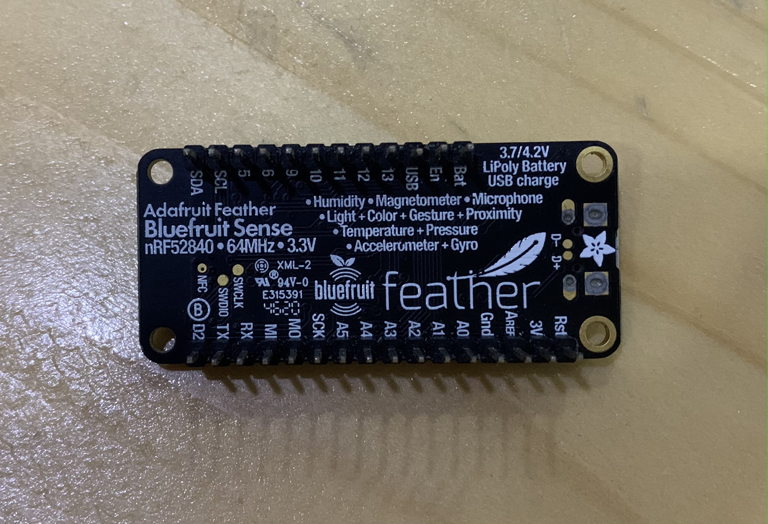
The microcontroller I used is Adafruit Feather M0 Bluefruit nRF52840 Sense
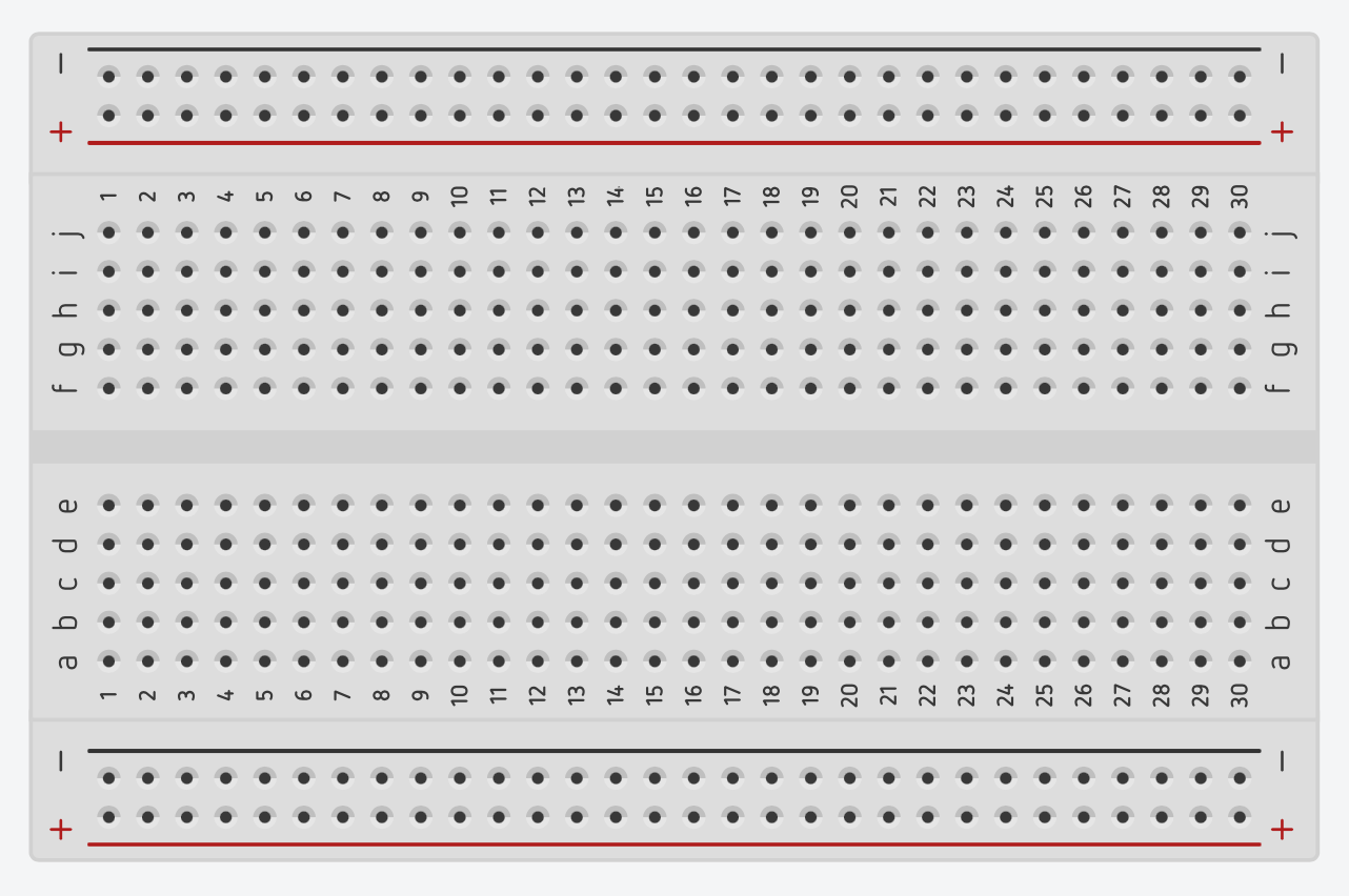
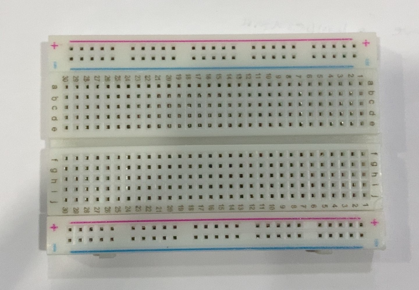
The breadboard; where everything is connected.
Fun Fact ✨
Do you know why the breadboard is called so?
The term breadboard comes from the early days of electronics, when people would literally drive nails or screws into wooden boards on which they cut bread in order to connect their circuits.
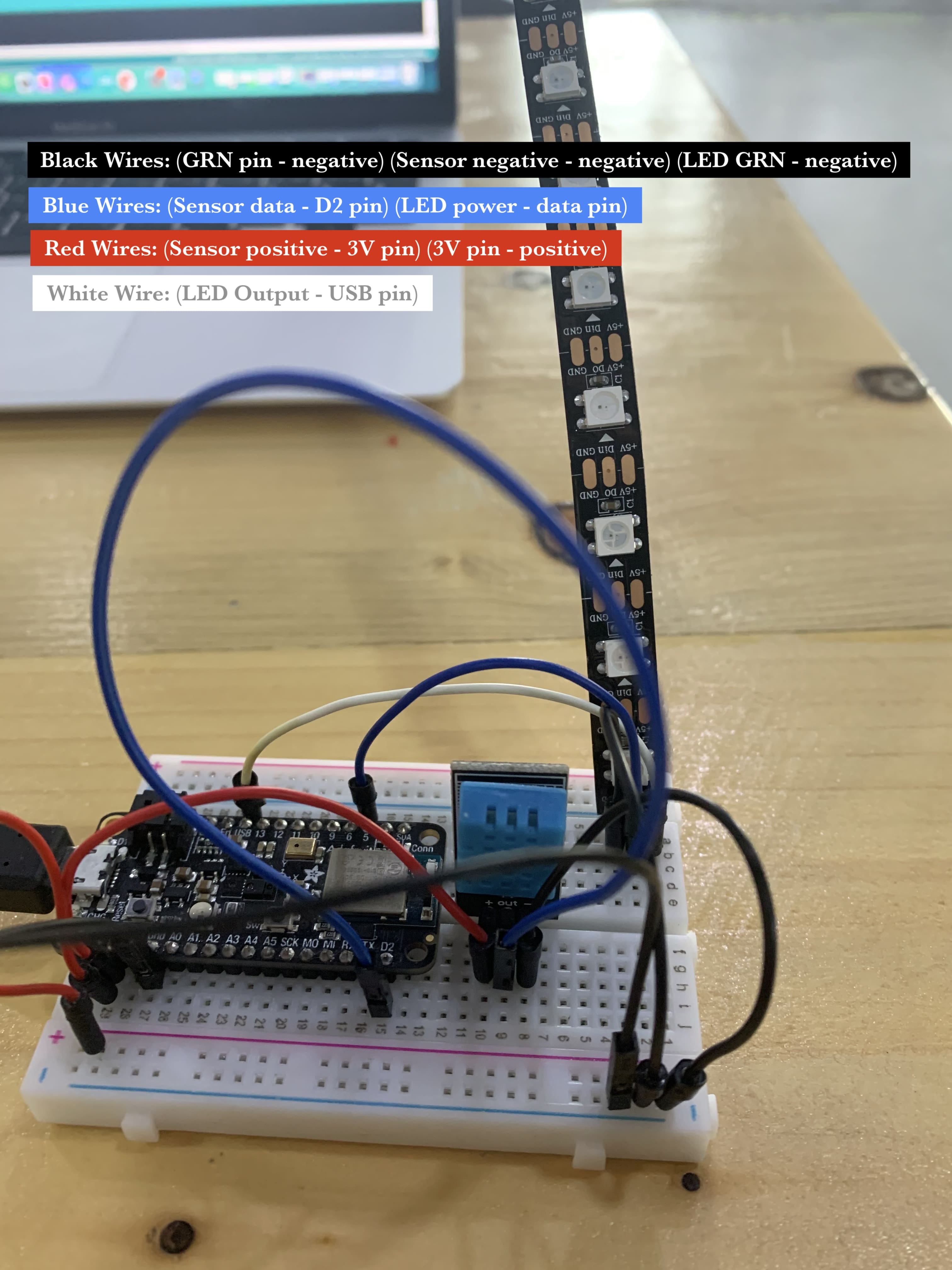
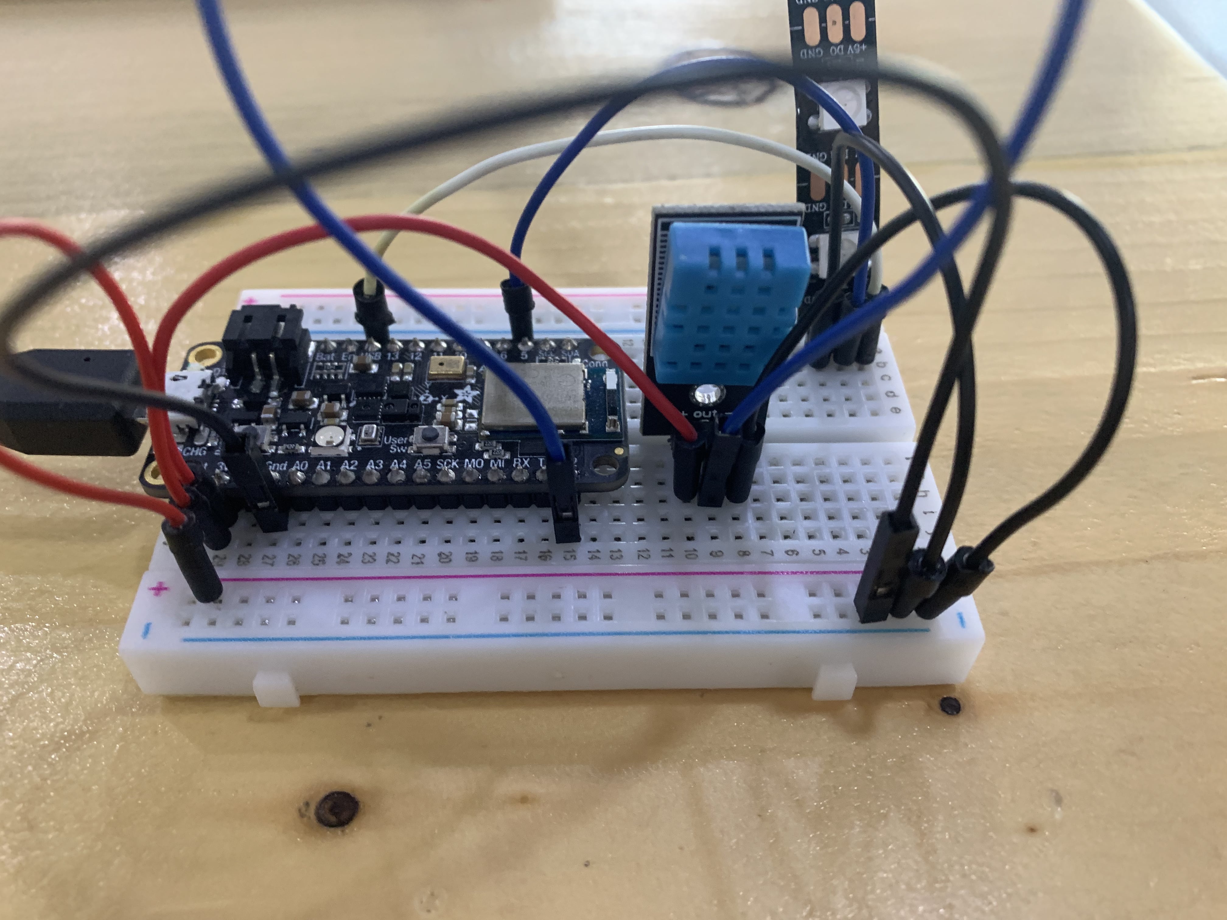
The connection

The Code
For the code I used FastLED library, you can find multiple examples from its library. This code controls the LED lights one by one with 0.5 seconds delay in between. In terms of the color you can change it as it is represented as RGB, Red Green Blue with quantity from 0 to 255, 0 being the minimum so no light and 255 being the maximum.
#include <FastLED.h> //library

#define LED_PIN     12 //The LED data pin
#define NUM_LEDS    8  //Number of LEDs

CRGB leds[NUM_LEDS];

void setup() {

  FastLED.addLeds<WS2812, LED_PIN, GRB>(leds, NUM_LEDS);

}

void loop() {

  //First LED light
  leds[0] = CRGB(150, 0, 255); //RGB color this shows a purple color
  FastLED.show();
  delay(500);  // 0.5 seconds delay
  //Second LED light
  leds[1] = CRGB(150, 0, 255);
  FastLED.show();
  delay(500);
  //Third LED light
  leds[2] = CRGB(150, 0, 255);
  FastLED.show();
  delay(500);
  //Fourth LED light
  leds[3] = CRGB(150, 0, 255);
  FastLED.show();
  delay(500);
  //Fifth LED light
  leds[4] = CRGB(150, 0, 255);
  FastLED.show();
  delay(500);
  //Sixth LED light
  leds[5] = CRGB(150, 0, 255);
  FastLED.show();
  delay(500);
  //Seventh LED light
  leds[6] = CRGB(150, 0, 255);
  FastLED.show();
  delay(500);
  //Eighth and last LED light
  leds[7] = CRGB(150, 0, 255);
  FastLED.show();
  delay(500);
}
The Result
I tried the LED strip lights with multiple colors as you can see here.

Input: Temperature & Humidity Sensor
The Hardware
I used a temperature and humidity sensor (DHT11). The DHT11 is a commonly used temperature and humidity sensor that comes with a dedicated NTC to measure temperature and an 8-bit microcontroller to output the values of temperature and humidity as serial data. And it has 3 connection points and they are;
- VCC; the positive, should be connected to the positive side or 3V pin
- The data; should be connected D2 pin
- The ground ; the negative, should be connected to the negative side

DHT11 spesifications:
- Operating Voltage: 3.5V to 5.5V
- Operating current: 0.3mA (measuring) 60uA (standby)
- Output: Serial data
- Temperature Range: 0°C to 50°C
- Humidity Range: 20% to 90%
- Resolution: Temperature and Humidity both are 16-bit
- Accuracy: ±1°C and ±1%
The connection

The Code
The code basically reads the temperature and humidity and if the temperature is 22.5 C or less then it is cold and the LED light should turn blue, and if the temperature is above 22.5 C than it is hot and the LED strip light should turn red. For this code I used the serial monitor to check if the sensor is working or not.
#include "DHT.h"
#include <SPI.h>
#include <FastLED.h>
#define DHTPIN 2
#define DHTTYPE DHT11
#define LED_PIN 5
#define NUM_LEDS 8
CRGB leds [NUM_LEDS];

DHT dht(DHTPIN, DHTTYPE);

void setup() {
  Serial.begin(9600);
  dht.begin(); // initialize the sensor
  FastLED.addLeds<WS2812, LED_PIN, GRB>(leds, NUM_LEDS);
  FastLED.addLeds<NEOPIXEL, LED_PIN>(leds, NUM_LEDS);
}

void loop() {
  // wait a few seconds between measurements.
  delay(2000);

  // read humidity
  float humi  = dht.readHumidity();
  // read temperature as Celsius
  float tempC = dht.readTemperature();


  // check if any reads failed
  if (isnan(humi) || isnan(tempC)) {
    Serial.println("Failed to read from DHT sensor!");
  } else {
    Serial.print("Humidity: ");
    Serial.print(humi);
    Serial.print("%");

    Serial.print("  |  ");

    Serial.print("Temperature: ");
    Serial.print(tempC);
    Serial.print("°C ~ ");

  }

  if (tempC<=22.5) {
    for (int i=0; i<8; i++) {
          leds[i] = CRGB(0,0,225); //blue
          FastLED.show();
    }
  }

   else if (tempC>22.5){
    for (int i=0; i<8; i++) {
          leds[i] = CRGB(225,0,0); //Red
          FastLED.show();
    }
   }

  }
The Result
I used the serial monitor to check if the sensor is working or not. In this video you can see that the temperature and humidity are changing.
Final Result
At the end, my input and output were Temperature & Humidity Sensor and LED Strip Light respectivly. The sensor reads the temperature and humidity and if the temperature is cold the LED light turns blue, and if the temperature is hot the LED strip light turns red. Here is a video that shows the input and output device working, you can notice the temperature and humidity reading on the screen behind.
