7. Input & Output devices
This week began with an introduction towards Input & Output Devices.
Refer to Week 04 for Introduction to Microcontroller, specifically Arduino.
Tasks Overview!
- INDIVIDUAL ASSIGNMENT:
1- Measure something: Add a sensor to a microcontroller board and read it.
2- Add an output device to a microcontroller board and program it to do something.
3- Document your work.
Input & Output Devices
In order for the circuit to work, there are some key factor devices, specifically Input and Output Devices.
What are Input Output devices?
These devices can be understood simply, by taking an example from our everyday use life: Switch!
When you turn the switch ON, it is considered as an INPUT. It is an order, sort of, that is given to the circuit to do the task it was assigned to do. By turning the switch ON, the lights in the room light up. That’s the final outcome, which is called OUTPUT.
Class Assignment!
We are asked to use our Microcontroller board, namely ARDUINO, to do the class assignment. The assignment here is to light up LED in the Breadboard, using pushbutton, and connect it with Arduino board.
Research
Upon searching and doing some research, I found the different components, needed to do this whole process. The Video Reference for the LED light with pushbutton and ARDUINO can be found here.
The components include:
1- Arduino Microcontroller board (with it’s USB connection).
2- Breadboard.
3- Pushbutton.
4- Jumper wires.
5- Resistors.
6- LEDs.
The Process - PART 01!
I started the process, by adding all the components above in the Breadboard, and connecting it with the the microcontroller.
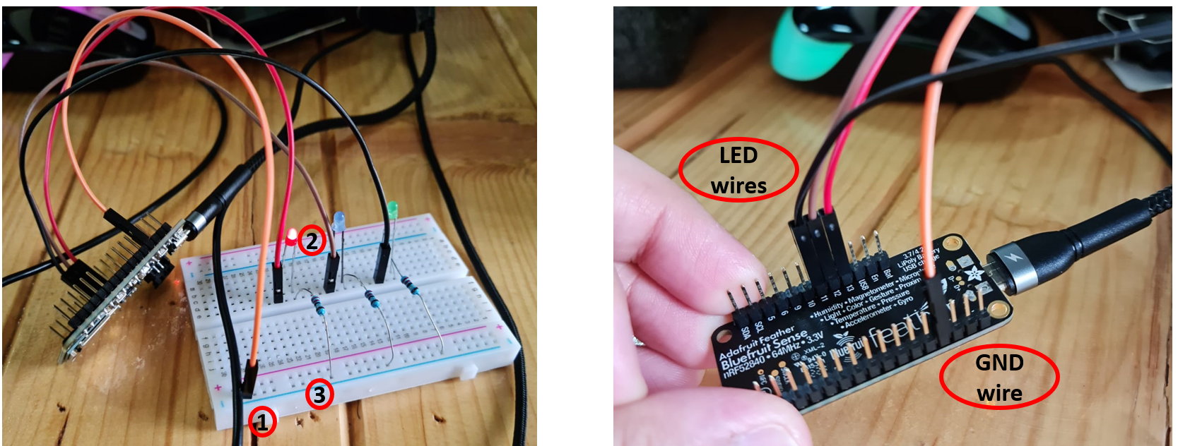
First, I inserted a jumper wire in GND of microcontroller, and attached it on the Negative blue line of Breadboard.
After that, I started adding my LEDs (R,G,B), and started adding Resistors on the same lines of the LEDs. These resistors were added to the negative blue GND line of the breadboard.
Next, the jumper wires were inserted, on parallel to the resistors, and connected to Pins 11, 12 and 13 of the microcontroller, respectively.
Then, I went to Arduino, and started setting the code for the process.
Problem - I didn’t notice!
I didn’t notice that my microcontroller board wasn’t connected to the ARDUINO software, which is the reason why the uploading wasn’t happenning and the other LEDs weren’t blinking (Red LED was on default, before the code was written).
VIDEO (Problem I didn’t notice)
Connecting AGAIN to MCU
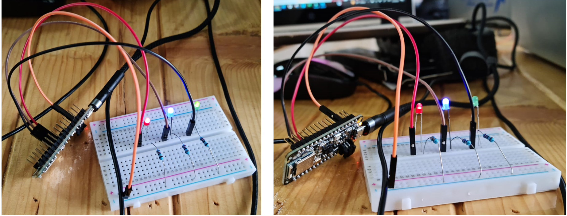
I connected the microcontroller board again, and started doing the process again, and this time, it worked.
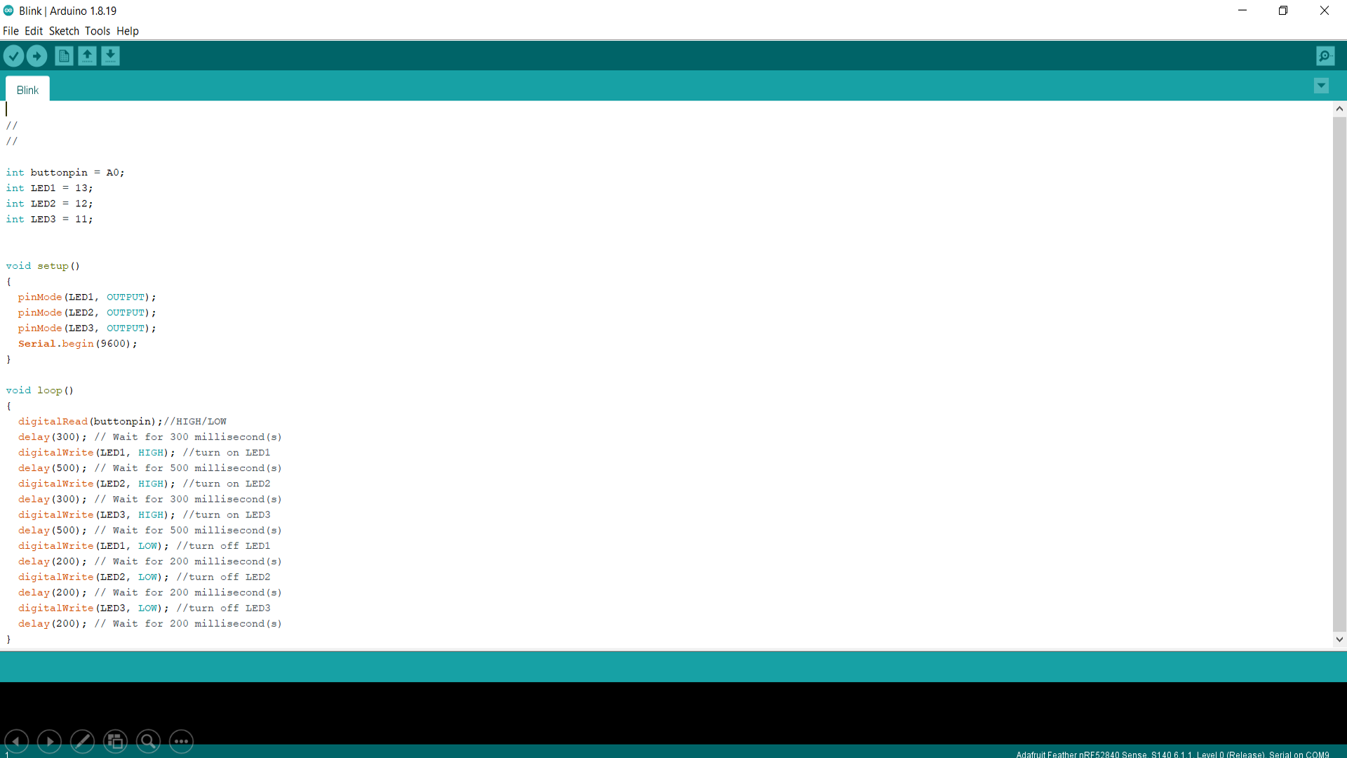
CODE
//
//

int buttonpin = A0;
int LED1 = 13;
int LED2 = 12;
int LED3 = 11;


void setup()
{
  pinMode(LED1, OUTPUT);
  pinMode(LED2, OUTPUT);
  pinMode(LED3, OUTPUT);
  Serial.begin(9600);
}

void loop()
{
  digitalRead(buttonpin);//HIGH/LOW
  delay(300); // Wait for 300 millisecond(s)
  digitalWrite(LED1, HIGH); //turn on LED1
  delay(500); // Wait for 500 millisecond(s)
  digitalWrite(LED2, HIGH); //turn on LED2
  delay(300); // Wait for 300 millisecond(s)
  digitalWrite(LED3, HIGH); //turn on LED3
  delay(500); // Wait for 500 millisecond(s)
  digitalWrite(LED1, LOW); //turn off LED1
  delay(200); // Wait for 200 millisecond(s)
  digitalWrite(LED2, LOW); //turn off LED2
  delay(200); // Wait for 200 millisecond(s)
  digitalWrite(LED3, LOW); //turn off LED3
  delay(200); // Wait for 200 millisecond(s)
}
VIDEO
The Process - PART 02!
Next, I started researching again, and tried the pushbutton process this time.
The pushbutton is usually placed, when we want to control something using the pushbutton.
The pushbutton acts as the input device, that sends signals through the wires to the desired location, which will display the main output result.
In this process, as described below, will showcase how the wires are setup, and when pushed the button, how it will show the result in terms of LED lights lighting up.
First, I connected ARDUINO board with USB cable to the laptop.
Then, I started doing the whole process.
1- On a breadboard, I placed the pushbutton in the middle of the board, and started adding the jumper wires. There are 2 wires, placed paralell to the button. On one end leg of the button, I placed, and inserted the wire and connected the other end of it with the Negative value GND (blue area of the breadboard). Another wire, I connected it with Pin10 of the microcontroller.
2- Next, I inserted LEDs into the board. LEDs have 2 pins, Longer pins and Short pins. Longer Pins are the positive Anodes, and the Shorter pins are the negative Cathodes.
After inserting the LEDs in the board, I added resistors next to them. These resistors are on the same line of LED, specifically of the same line as negative cathodes. and these resistors will connect with the GND blue line of the board.
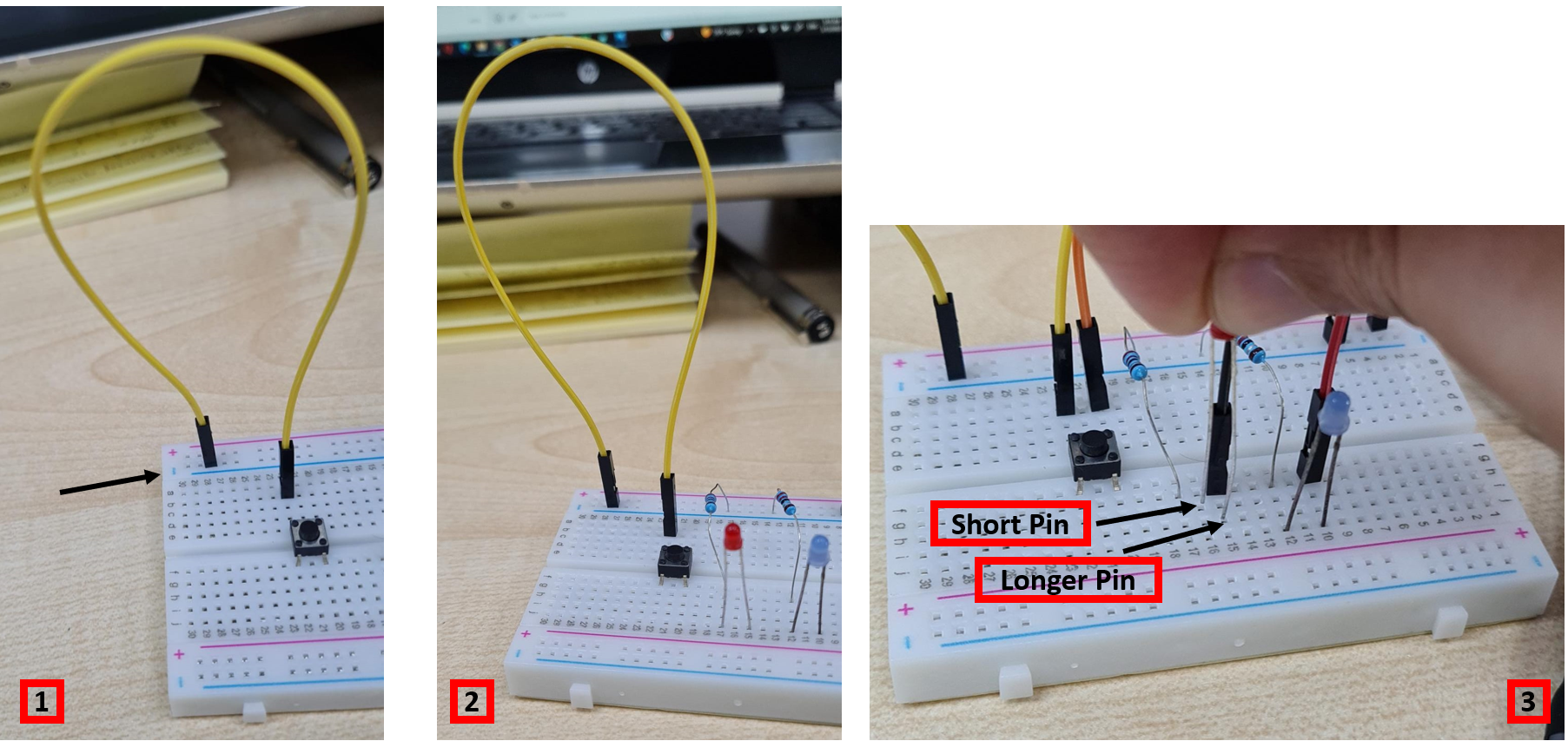
3- After adding resistors in the board, now jumper wires were inserted on the anode positive parts of the LED. These jumper wires were connected to the microcontroller board, specifically to the Pins 12 and 13.
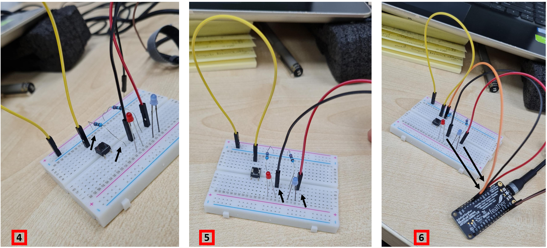
4- Now, for the power from the Microcontroller board, 2 more jumper wires were added in the board. One wire connected GND of microntoller, with the negative blue line on the breadboard. Another wire connected the 5V or 3V voltage of microcontroller board to the red positive line on the breadboard.
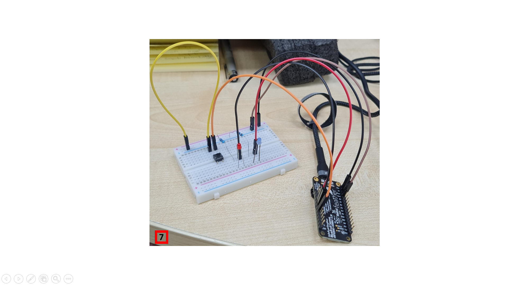
Now, the setup is finished. We move on to ARDUINO software, for making the code for the whole process to work on.
ARDUINO CODING
Here, as shown below, shows the coding that is done for the process, that will light up the LEDs (Output), by simply pushing the button (Input).
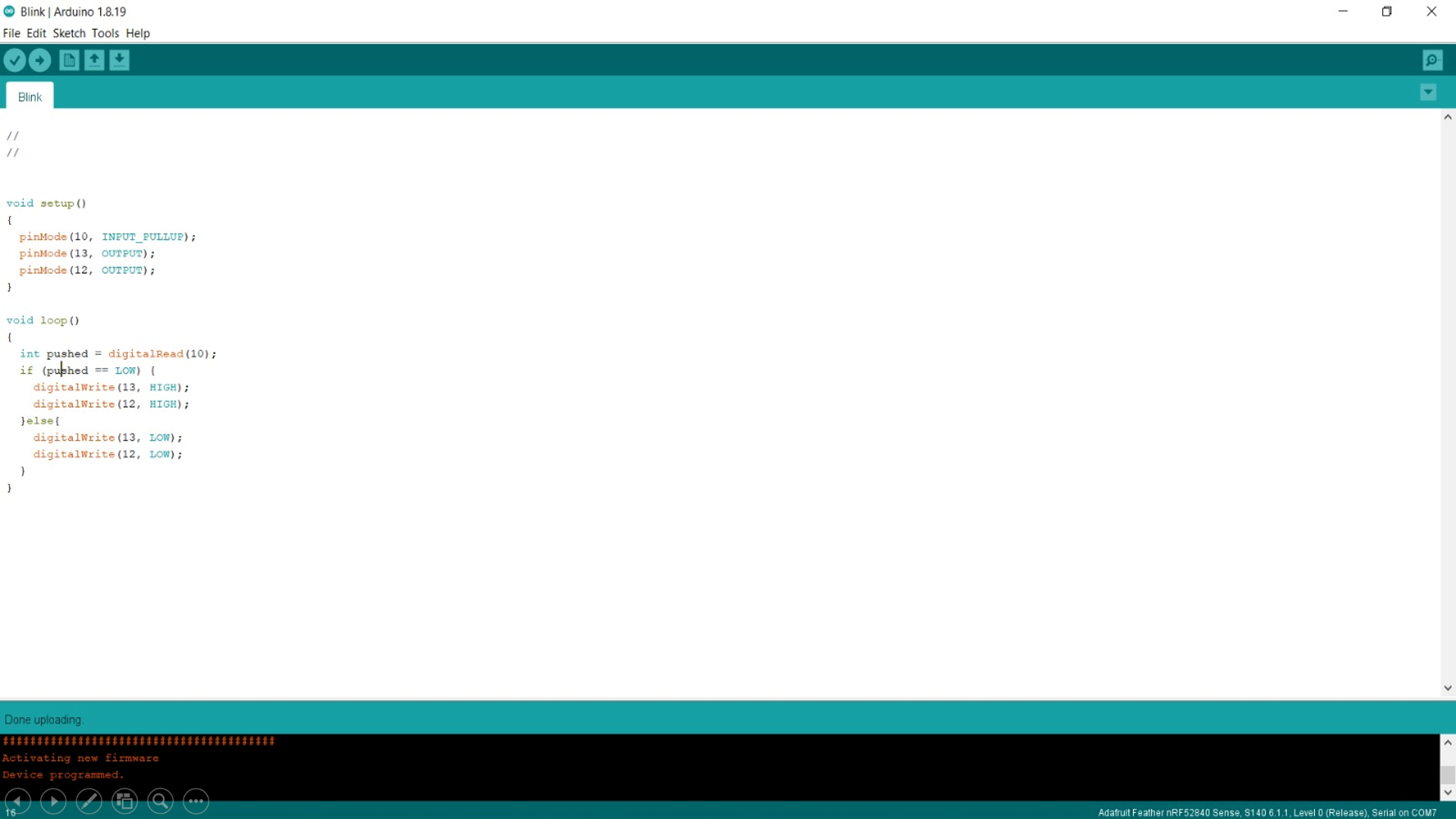
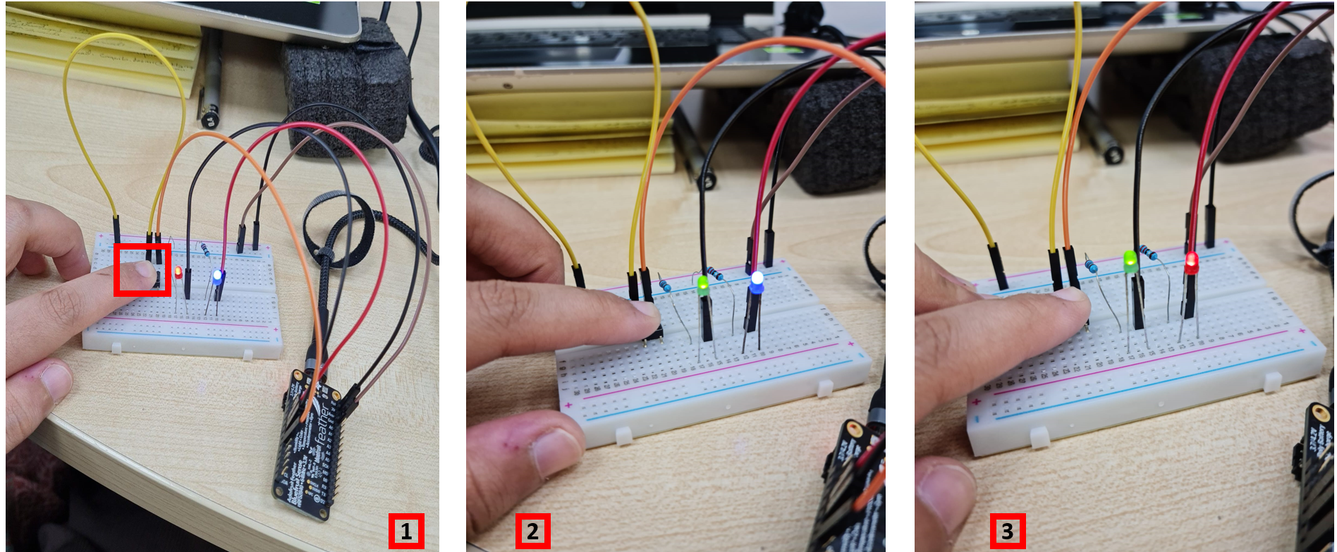
As a result, in the end, it shows that when the pushbutton is pressed, it sends the signals through the wires, which ends in displaying the output results in the LED lights.
When the button is pushed, the LED lights turn ON, and when we release the button, the LED lights turn OFF.
CODE
//
//


void setup()
{
  pinMode(10, INPUT_PULLUP);
  pinMode(13, OUTPUT);
  pinMode(12, OUTPUT);
}

void loop()
{
  int pushed = digitalRead(10);
  if (pushed == LOW) {
    digitalWrite(13, HIGH);
    digitalWrite(12, HIGH);
  }else{
    digitalWrite(13, LOW);
    digitalWrite(12, LOW);
  }
}
FINAL VIDEO
CHALLENGE TIME!!
We are asked to do one of the following from below:
EASY MODE:
Use the one of the sensors on the Adafruit & try to program to display its results in the serial monitor + to be represented by an LED &/or Buzzer
MEDIUM MODE:
Use a variable resistor as an input to to control either the speed or the direction of the servo motor.
HARD MODE:
Try to create a small automated farming system using the light sensor & the servor motor. Where it’s according to sun day the plant start be filling by the water.
EXTREME MODE:
Creat a cooling system using a fan, variable resistor, Temperature sensor & an LCD. The idea is to control the fan automatic & manually. You can adjust the fan coolness automatically using the temperature sensor to increase or decrease the fan rotation and display its on the LCD. Or switching the to maual mode where you rotate the variable resistor according to how fast you want the fan to go and it should be display on the LCD screen.
EASY MODE!
I decided to go with the easy mode. The easy mode assignment is as follows:
“Use the one of the sensors on the Adafruit & try to program to display its results in the serial monitor + to be represented by an LED &/or Buzzer.”
Referring back to Week o4 of “Embedded Programming”, I had searched about different features of Adafruit, where few of its features included the sensors that are built-in already in adafruit. The task here is to use one of those sensors, and to try to create its result, by displaying it in Serial Monitor, and also seeing it in the form of LED representation.
So, I referred back to my Week 04, and went through the “sensors of Adafruit”, by visiting this page: ADAFRUIT. This link can also be found in Fablab’s Website, by going to “RESOURCES”, and Selecting “Adafruit features overview”.
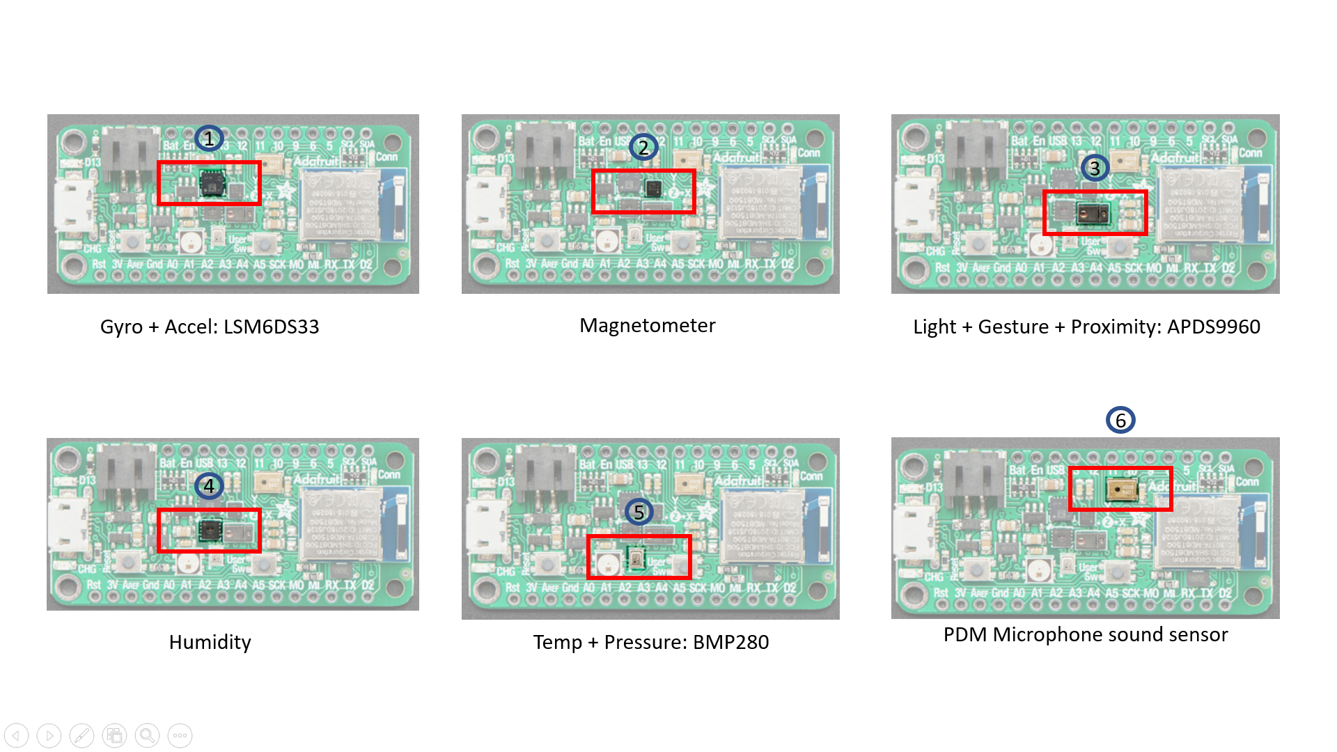
There are several types of sensors integrated in the microcontroller, including:
1- Gyro + Accel: LSM6DS33, which is an accelerometer + gyroscope. The 3-axis accelerometer, can tell you which direction is down towards the Earth (by measuring gravity) or how fast the Feather Sense is accelerating in 3D space.
2- Magnetometer: LIS3MDL, which sense the magnetic fields that surround us. Magnetometers can sense where the strongest magnetic force is coming from, generally used to detect magnetic north, but can also be used for measuring magnetic fields.
3- Light + Gesture + Proximity: APDS9960, - Detect simple gestures (left to right, right to left, up to down, down to up are currently supported), return the amount of red, blue, green, and clear light, or return how close an object is to the front of the sensor.
4- Humidity: SHT30, This sensor has an excellent ±2% relative humidity and ±0.5°C accuracy for most uses. Sensor is I2C on standard pins, address 0x44.
5- Temp + Pressure: BMP280, This sensor is a precision sensing solution for measuring barometric pressure with ±1 hPa absolute accuracy, and temperature with ±1.0°C.
6- PDM Microphone sound sensor: MP34DT01-M - PDM sound sensor.
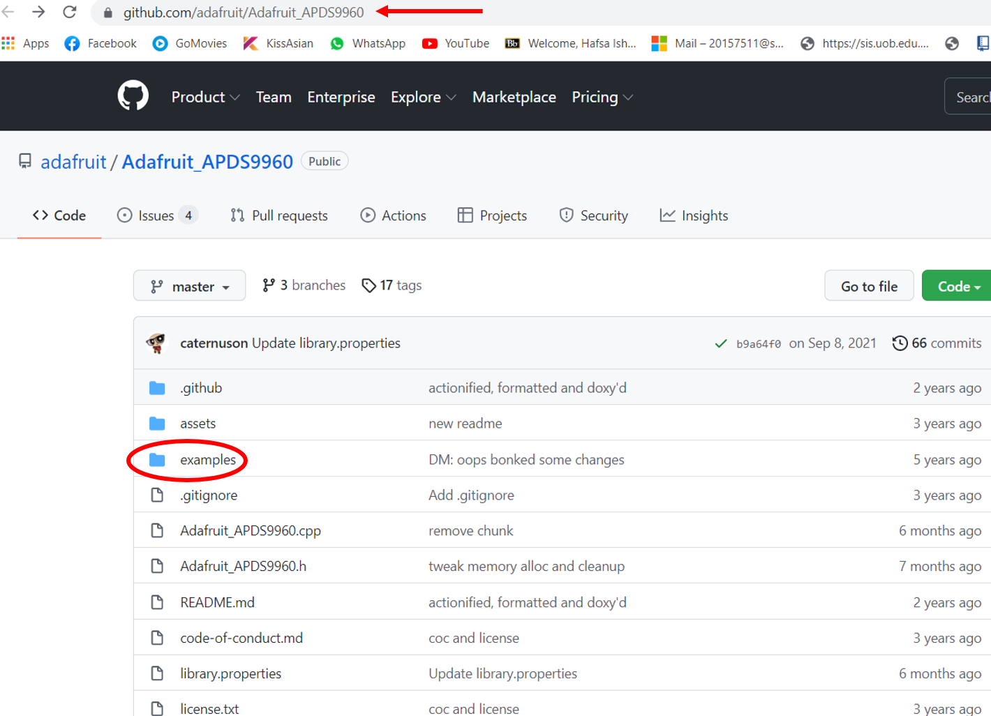
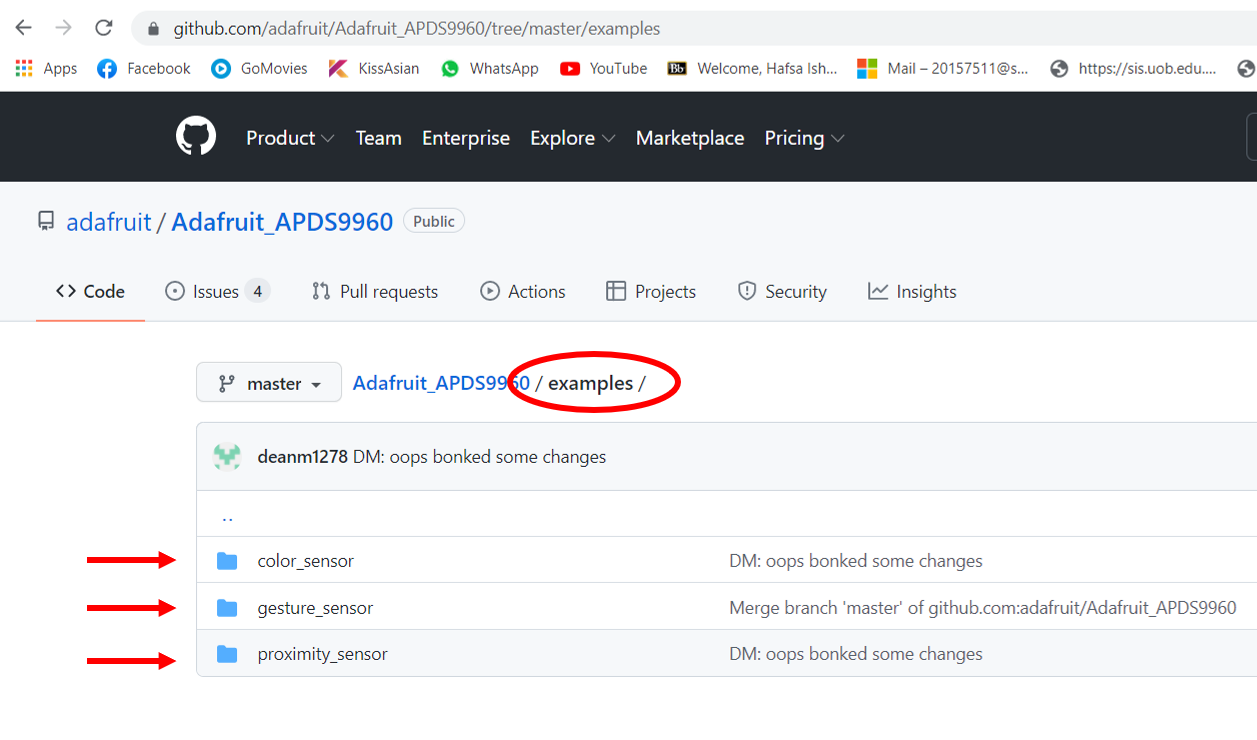
The site contains a number of coding examples: Adafruit examples
Light Detecting Sensor, with Buzzer
Out of all the sensors, I decided to go with “Light detecting sensor.”
In this assignment, I decided to see the light’s affect on LED.
Here is a Youtube Link reference, that I was inspired from. I followed the steps of connections, as shown in the video below.Also, the site reference for the code is as follows: LDR & LED with Arduino - Sound Alarm
Reference Video!
Components
Now, in order for this whole process to work, we need the following:
1- Arduino board
2- LED light
3- LDR (PhotoResistor)
3- Buzzer
4- 10k & 220 ohm Resistor
5- Breadboard
6- Jumper wires
Steps!
In order for this to work, I took the LDR, which is the light detecting sensor, and functioned and programmed the code in a way, that it would start making sound when light is detected, and not making any sounds when there is no light detection.
So, in this process, the light served as the main input device for the sensor, which resulted in the buzzer making sounds out of it. And when there was no light detection, the buzzer went OFF too.
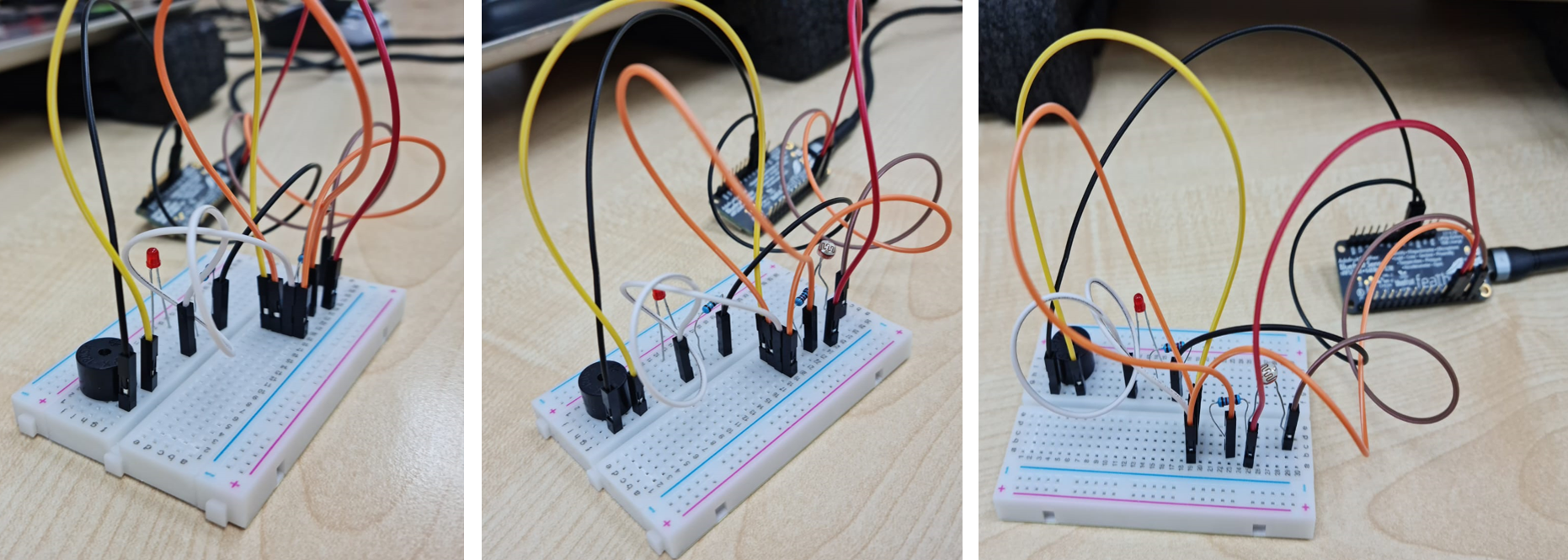
I started by attaching USB cable wire with the Arduino board, and started working on the steps.
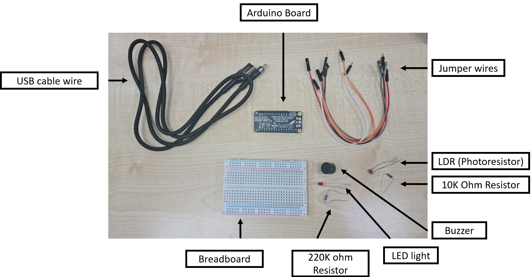
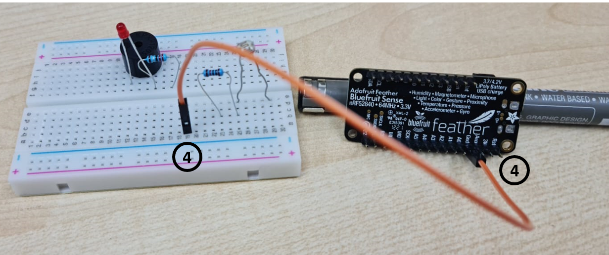
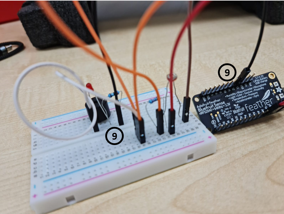
1- First, I added the Buzzer in the board.
Key point to note: The longer pin of the buzzer is positive, while the shorter pin is negative.
2- Second, I put the LED light in the board as well.
Key point to note: The longer pin of the LED is positive, while the shorter pin is negative.
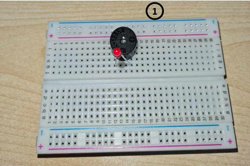
3- Third, the 220k ohm Resistor was inserted in the board, on the same line as that of the longer pin of LED (Longer pin - positive).
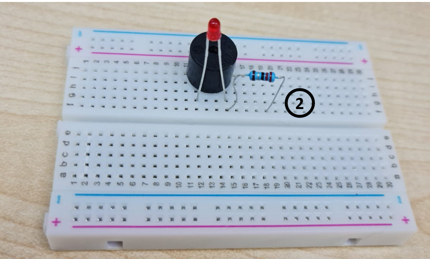
4- Next, I added the LDR (PhotoResistor) in the board.
5- Then, 10K Resistor was attached on one leg of LDR.
6- Afterwards, I attached one jumper wire to GND of the Arduino board, and connected the other end on the breadboad (GND).
7- Next, another wire was connected with the buzzer’s small pin line (negative), and connected to GND of the board.
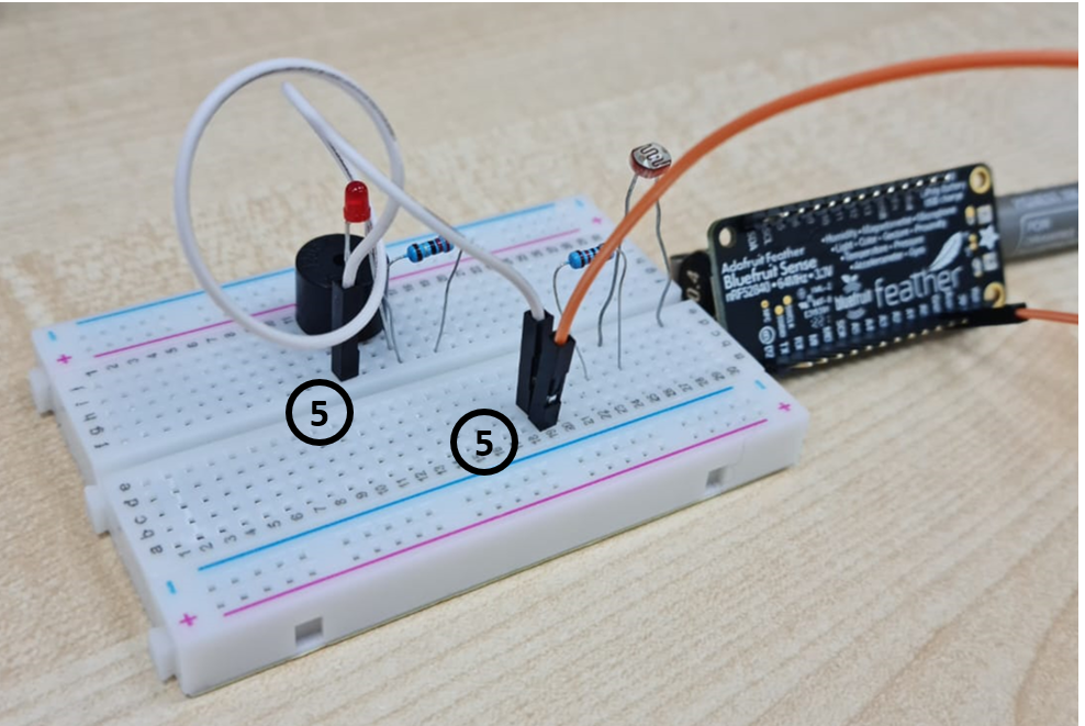
8- On one end of the 10K Resistor (near LDR), another wire was attached on the same of the resistor, and connected to GND of the breadboard.
9 - Next, one more wire was connected to LDR’s (PhotoResistor) same line, and the other end of wire was connected to 3V voltage of Arduino board.
10- And lastly, one last wire was connected to Analog pin A0 of the Arduino board, and connected with LDR (PhotoResistor) & 10K ohm resistor’s same column leg line.
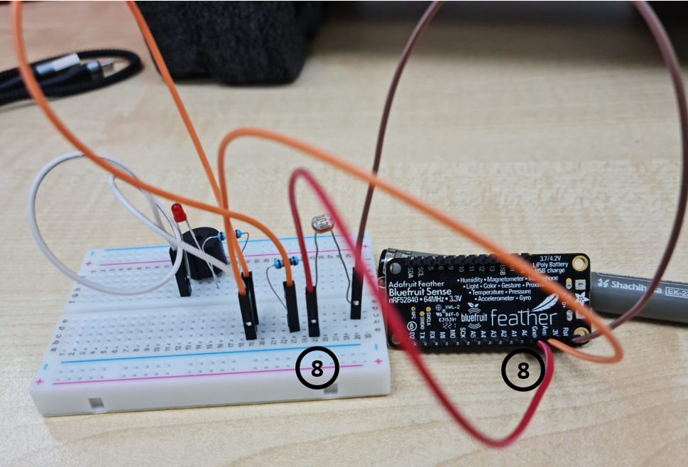
11- Afterwards, one more wire was connected to Pin 13 of Arduino board, and it’s other end was connected to 220K ohm Resistor’s empty leg lines.
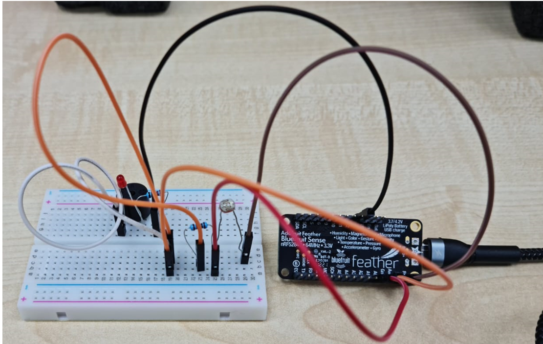
Now, the circuit is complete. It is time to do the coding.
Code Try-out!
#include <SoftwareSerial.h>

//set pin numbers

const int ledPin = 13;
const int buzzerPin = 12;
const int ldrPin = A0;

void setup () {

  Serial.begin(9600);

  pinMode(ledPin, OUTPUT);
  pinMode(buzzerPin, OUTPUT);
  pinMode(ldrPin, INPUT);
}

void loop() {

  int ldrStatus = analogRead(ldrPin);  //read the state of the LDR value

  if (ldrStatus >= 400) {

    tone(buzzerPin, 100);
    digitalWrite(ledPin, HIGH);
    delay(100);

    noTone(buzzerPin);
    digitalWrite(ledPin, LOW);
    delay(100);

    Serial.println("----------- ALARM ACTIVATED -----------");
  }
  else {

    noTone(buzzerPin);
    digitalWrite(ledPin, LOW);

    Serial.println("ALARM DEACTIVATED");
  }
}
Issues & Changes!
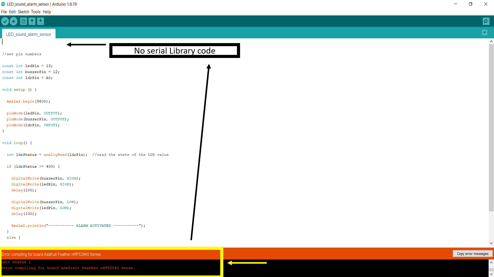
When I tried to do coding, it showed some errors. Some of these include:
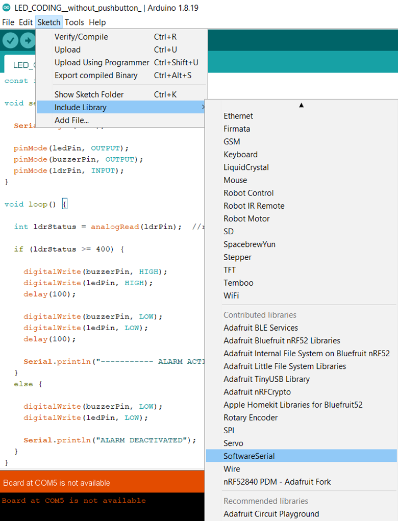
1- Softwareserial: (#include SoftwareSerial.h) I had not included the Serial laylout coding, which is why it showed me this error. With the help of my colleague Weaam, I was able to quickly resolve the issue, by going to “Sketch” in Arduino, then clicking on “include library”, and selecting “SoftwareSerial”.
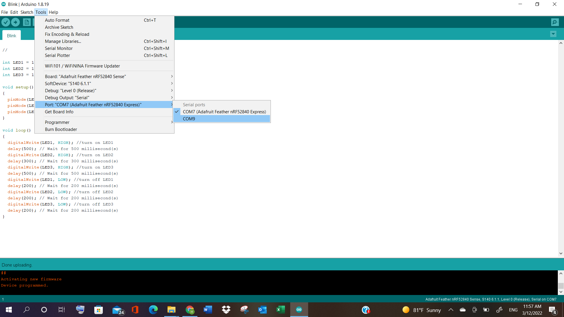
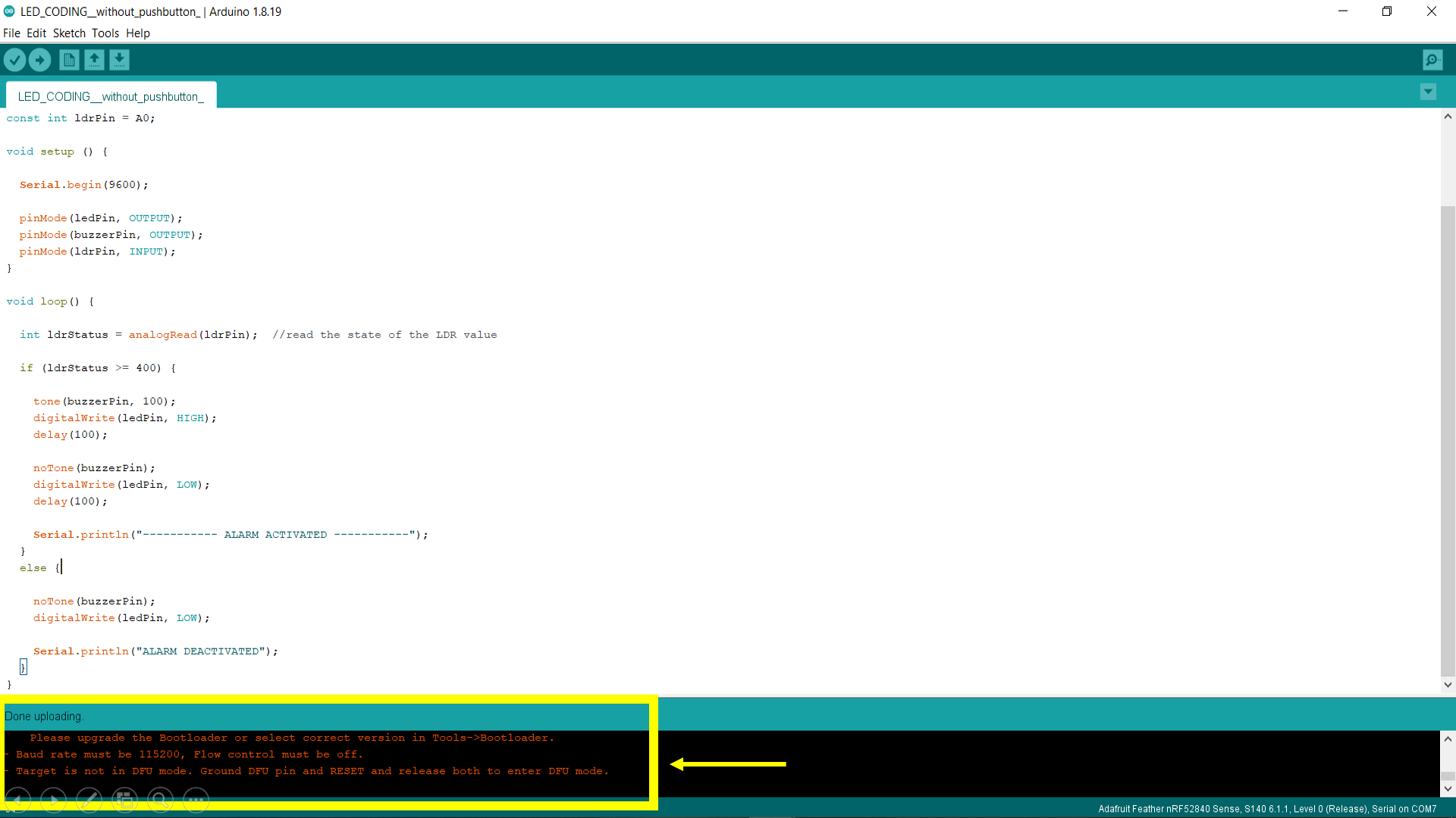
2- Bootloader + Adafruit Sense: I had not selected Adafruit Sense, which is another reason for error. Also, there was a message that showed to update bootloader. But it seems that I had not selected the proper port, which is why it showed errors.
Video Tryout!
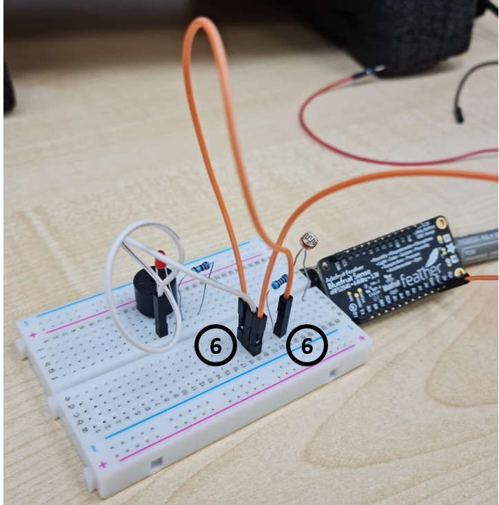
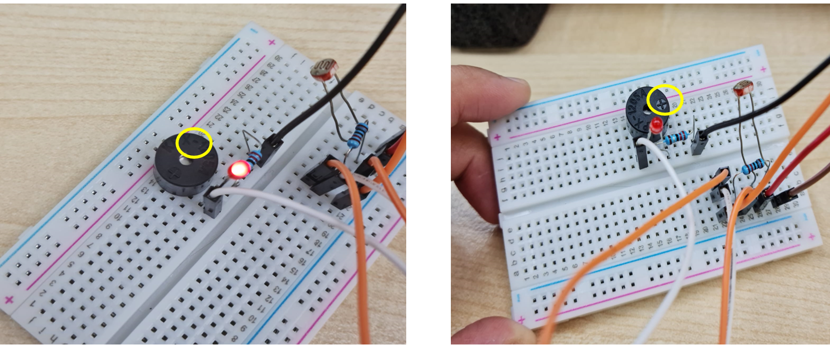
3- No Sound: After I went through the video, and followed all the steps and did the wire connections, and I tried out the final result, but there was no sound.
So, with the help of my instructor Haitham, we changed the placement of some wires and Buzzer, and rearranged them near LED light, and it started working, and the device started making tones and sounds.
Final Code!
After the changes, I tried to update the code and start doing the uploading process again. The final code is as follows:
#include <SoftwareSerial.h>

//set pin numbers

const int ledPin = 13;
const int buzzerPin = 12;
const int ldrPin = A0;

void setup () {

  Serial.begin(9600);

  pinMode(ledPin, OUTPUT);
  pinMode(buzzerPin, OUTPUT);
  pinMode(ldrPin, INPUT);
}

void loop() {

  int ldrStatus = analogRead(ldrPin);  //read the state of the LDR value

  if (ldrStatus >= 400) {

    digitalWrite(buzzerPin, HIGH);
    digitalWrite(ledPin, HIGH);
    delay(100);

    digitalWrite(buzzerPin, LOW);
    digitalWrite(ledPin, LOW);
    delay(100);

    Serial.println("----------- ALARM ACTIVATED -----------");
  }
  else {

    digitalWrite(buzzerPin, LOW);
    digitalWrite(ledPin, LOW);

    Serial.println("ALARM DEACTIVATED");
  }
}
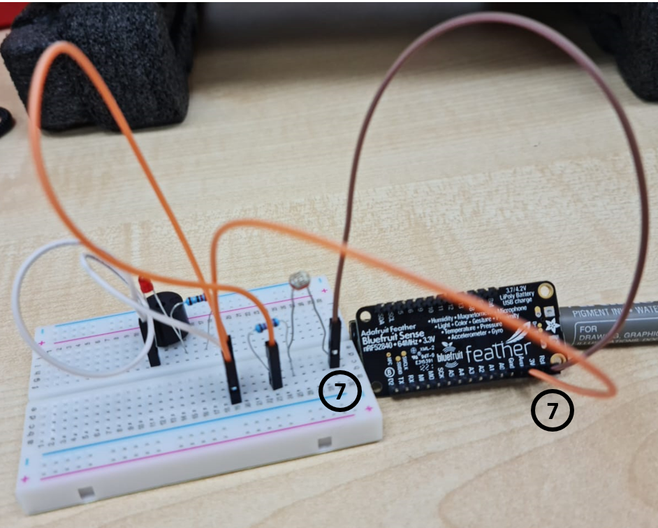
So what really happens is that the LDR is a Light-dependent resistor where its resistance changes when the light changes. We connect it to a voltage divider (the resistor) so we can read different levels of voltage when different light levels are present. The microcontroller then reads the different voltage levels via an Analog to Digital converter pin. And the final results are also seen in a serial monitor display, which shows “Alarm Activated” when explosed to light, and shows “Alarm deactivated” when put away from light. The buzzer has a resistor connected to it too, that detects the signals from LDR, and creates or makes an output based on that. When it detects that the LDR is exposed to light, the buzzer starts making sound, but when LDR is hidden from light, the buzzer takes that signal and stops making any sounds.
Video - FINAL RESULT + Serial Monitor Display!
Extra Video to note about the buzzer!
If we place the negative side of the buzzer pin on the same line as that of the LED and resistor, it wont make a sounds. However, if we keep it as positive on the line of resistor and LED, it will start making sound.
HAND GESTURE Video I want to try out!
hand gesture youtube and his site Robojax.
How to control Servo motor with Arduino with and without potentiometer