6. Large format CNC (computer controlled Machining)
Tasks Overview
- GROUP ASSIGNMENT:
1- Test runout, alignment, speeds, feeds, and toolpaths for your machine.
2- Document your work (in a group or individually).
- INDIVIDUAL PROJECT:
1- Make (design+mill+assemble) something big.
Introduction!
This week, we were introduced to Large format CNC cutting machine.
What is CNC machine?
CNC machines are making parts around the world for almost every industry. They create things out of plastics, metals, aluminum, wood and many other hard materials. The word “CNC” stands for “Computer Numerical Control”, but today everyone calls it CNC.
Click for more information on CNC.
GROUP ASSIGNMENT!
For the group assignment, we were shown a previous sample done by the previous batch of students, and we discussed the fitting joints process.
See in the below section - the picture of joints.
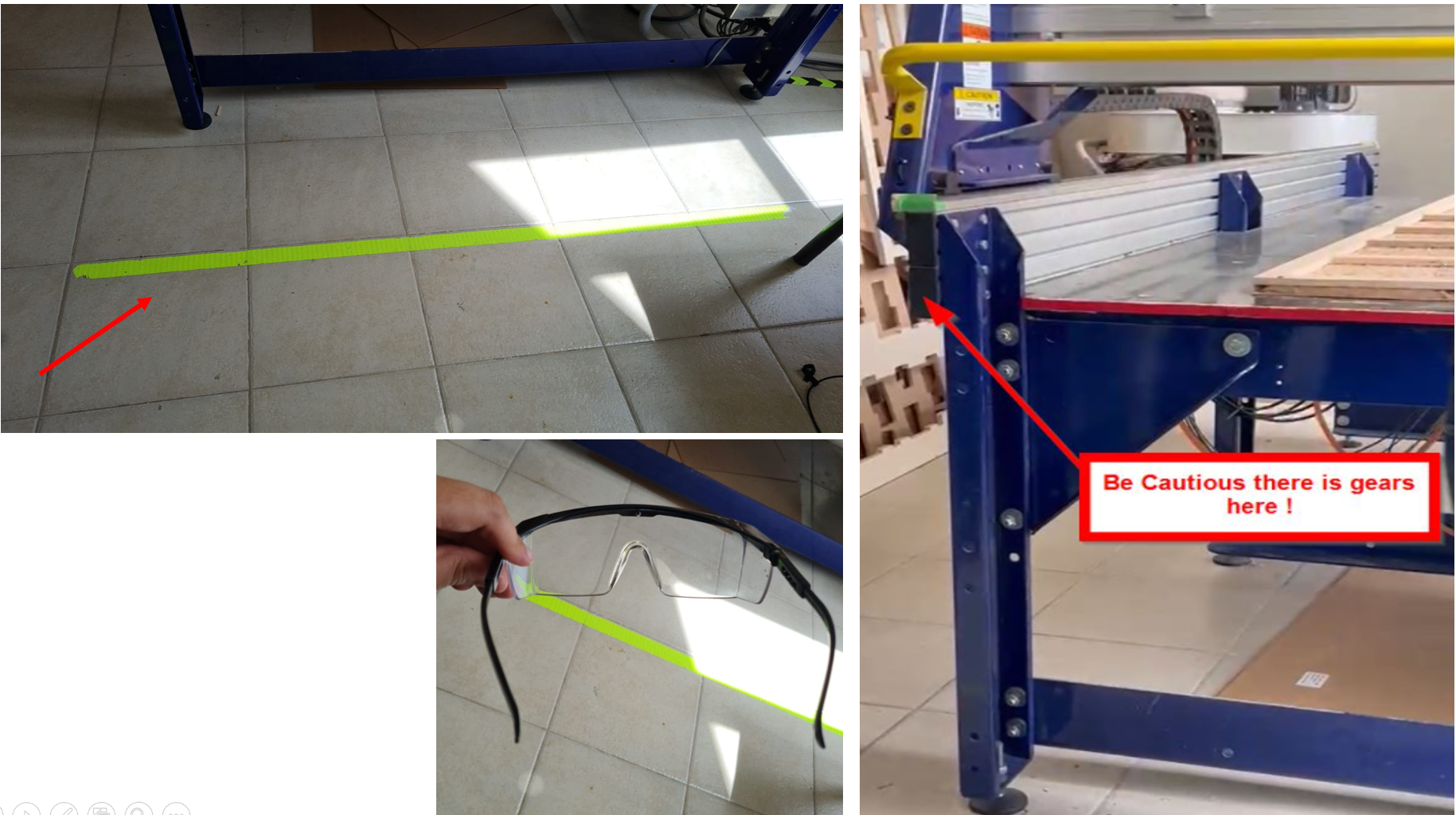
Safety Protocols
Before we move on to the cutting process of CNC machine and design, there are some safety protocols, that should be considered:
1- Yellow line: Don’t cross when machine is working, as it is dangerous.
2- Loose clothing: Avoid wearing loose hijab and tighten the wrist area.
3- Wear goggles when working, because dust is there, due to cutting process.
4- Wear Shoes, and not slippers etc.
Image Reference: Weaam Ajoor’s Website (Colleague)
Some image references for the CNC machine are taken from my colleague Weaam’s website.
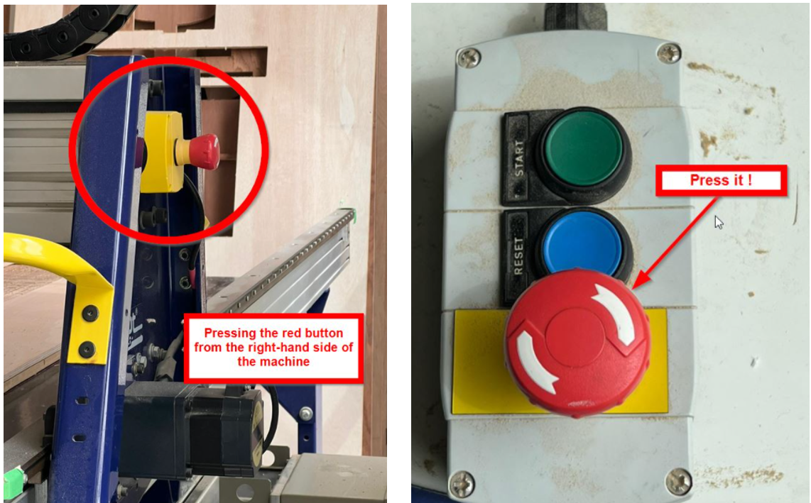
Emergency Buttons
In case of anything going wrong, there are 2 buttons that could be used to let the machine immediately stop working:
1- One button is on the main table.
2- Another button is on the side of the machine, for it to stop working.
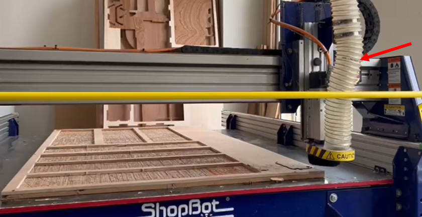
Size of the drilling bot
The side of the drilling bot is 3mm, so that it cuts smoothly with certain speed.
Vacuum
There is a tube vacuum on the top, connecting to the drilling bot. It helps in removing dust etc. from the cut areas, so as to clean the spaces from any dust particles.
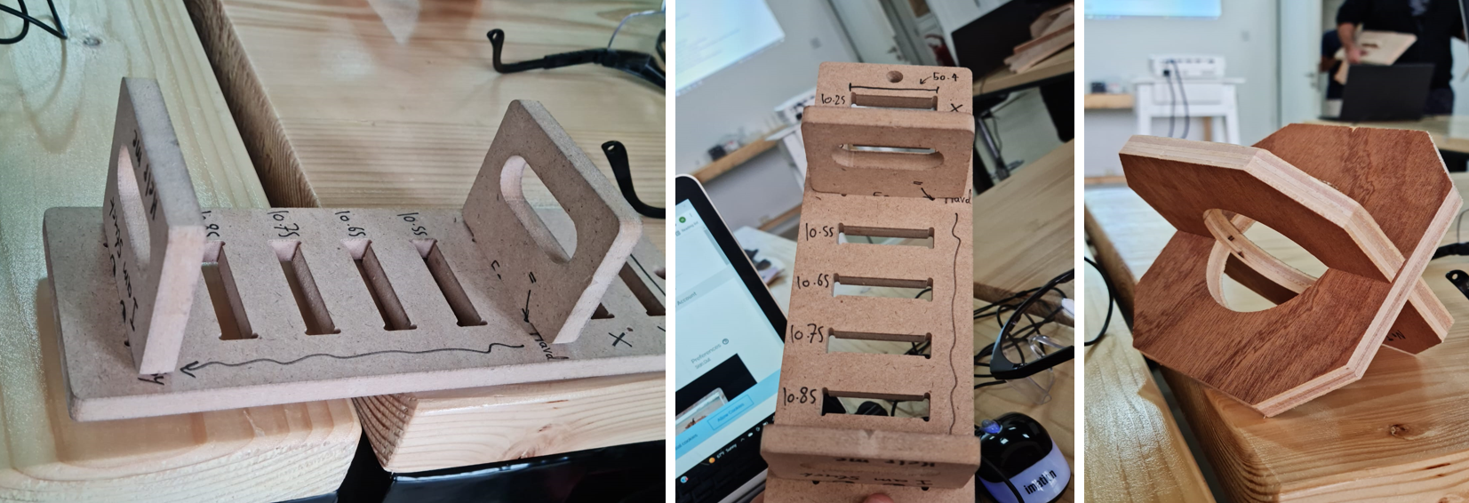
Joints
There are many joints that could be used to connect 2 woods together. Here is an example of joint connection, with 10.95 measurements, that is good for this material to fit together, without loosening up.
Group Assignment Link: Yusuf Yaqoob’s Website (Colleague)
For more information on the group assignment, please refer to my colleague Yusuf’s website.
INDIVIDUAL ASSIGNMENT!
Now, we proceed with making the design for the CNC machine to cut.
I wanted to do a chair design. The software used for this process is FUSION 360 (Refer to week05: 3D printing and Scanning document, for the software description).
The reference for the chair design can be found from this tutorial: Lounge Chair
Another reference for this CNC assignment can be found in this video: CNC Router with Fusion 360, Bookshelf Tutorial
Designing Phase: Lounge Chair!
I started making my design in Fusion 360. By taking the Lounge chair as my reference, I started making the design in the software. The sketch was made first roughly, before going forward with the design.

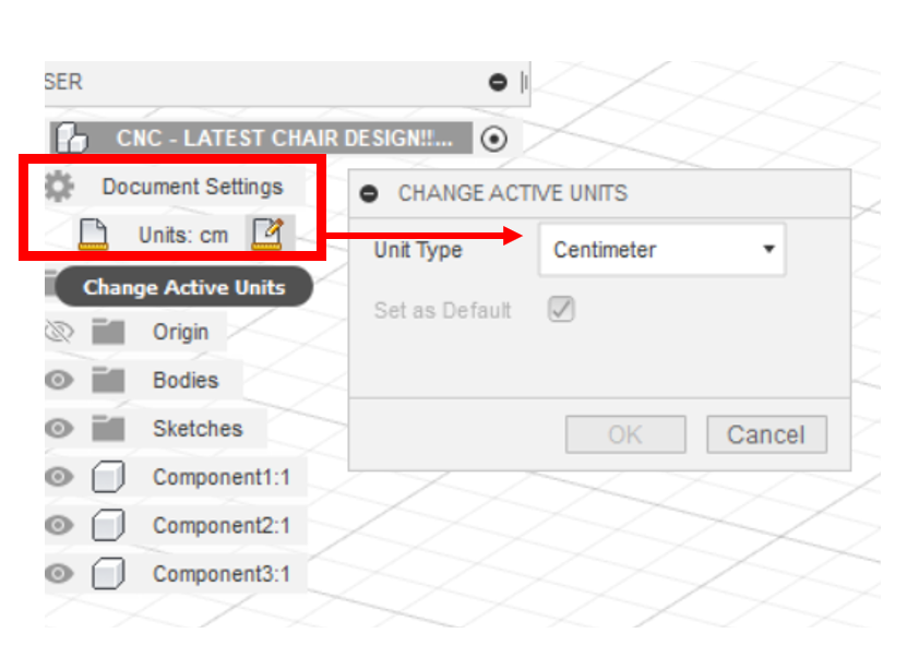
The wood board’s measurements are: 244cm x 122cm x 1.2cm (12mm).
1- First, I went to settings, under Documentation tab, and changed the units to “cm”.
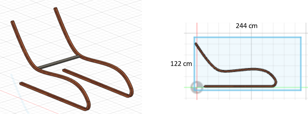
2- I made the curvy design of chair, but to be on the safe side, I wanted to see if it fits the board.
3- I sketched the outlining of the wood dimensions in Sketch area.
4- I saw that the design is bigger than the wooden board’s dimensions, so I started making it again from the scratch.
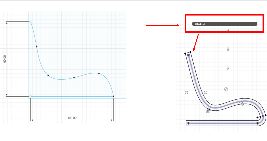
5- I started making my chair design, by starting with the curve part of it, and sketching it so as to ensure that it fits the wooden board. The curve depth was 3cm, then it became 4cm, with 1.2cm thickness (thickness of the wood: 12mm) to it.
6- After I made the curvy sides, I mirrored it to the other side, and started working on the middle horizontal portion now.
7- The middle portion pieces are the ones that will connect the two pieces together. I started making the length of it as 75 cm, and started adding joints on one side of the sketch. The length of the middle piece was 3cm, with joint as 1cm.
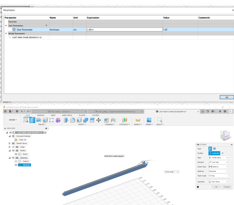
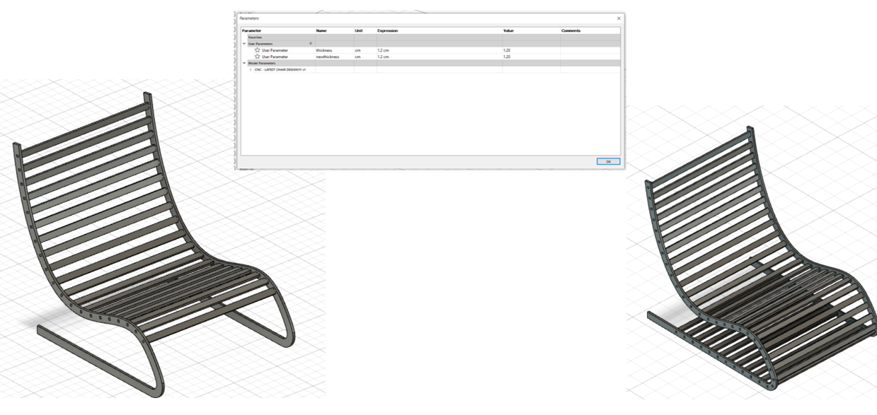
8- Since the thickness of the wooden board is 1.2 cm, so I made a parameter, and gave it the name of thickness with 1.16 cm value. The reason being, that one piece thickness should be smaller than the other one, so it can fit.
9- After making the joint sketch on one side, I mirrored to the other end, and finished the sketch. And then I extruded the sketch to the thickness of 1.2 cm.
10- After extruding it,I started to attach the middle piece with the 2 curvy bodies.
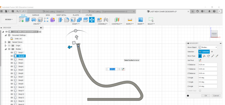
11- When I added it, I went to “Create” option, and selected “Pattern” and chose “Pattern on Path”. This feature allows me to select this one piece, and make copies of it in the chair design, without having to do it manually for each further piece connections.
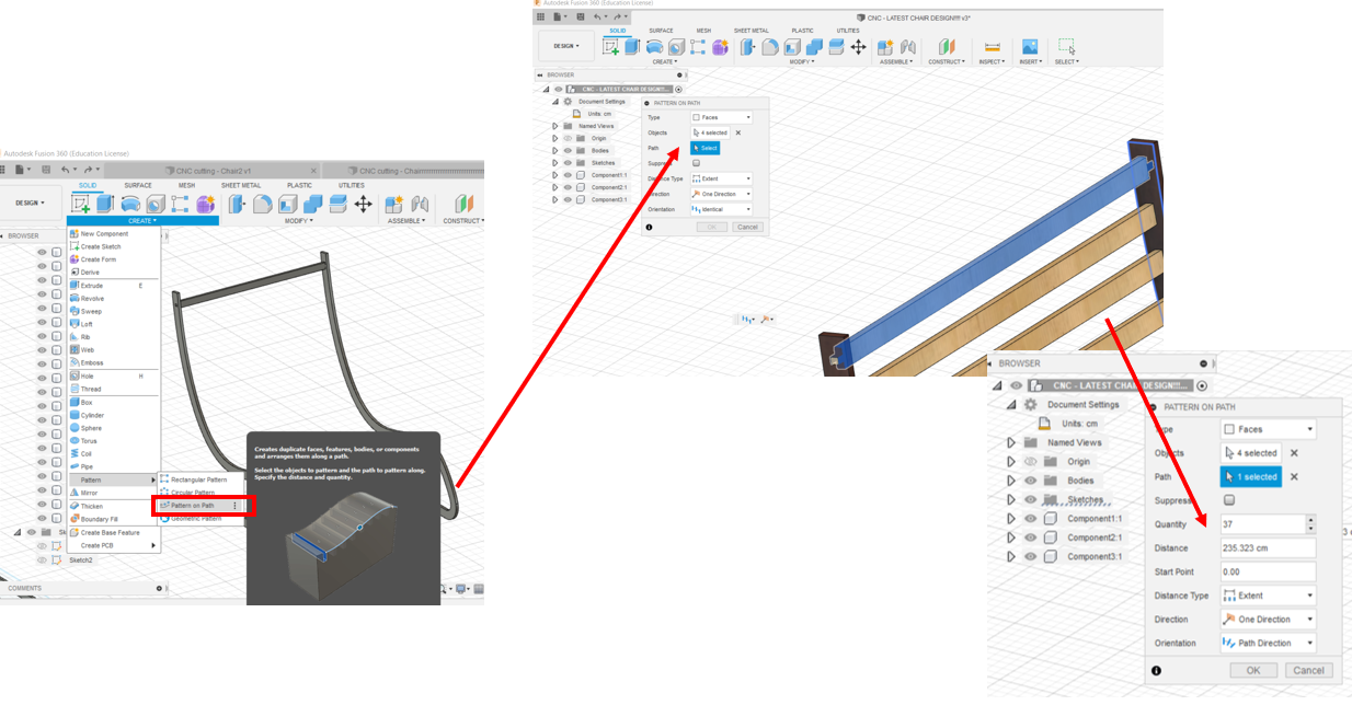
12- After making the pathway, the chair design connection is now complete. Now, we need to combine all such pieces.
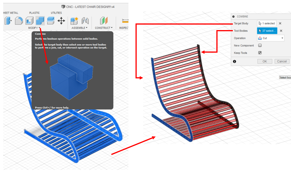
13- For this process, we select “Combine” from the top tab, and select one curvy body as the “target body”, and the middle portion as “tool bodies”. This will make cut pieces in the curvy part, ensuring us that the wood is cutting from this area.
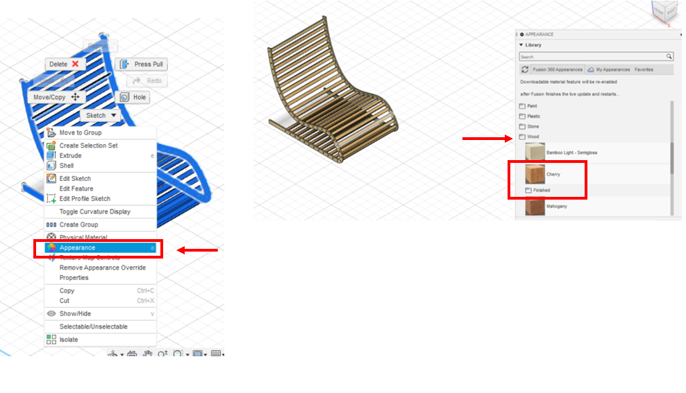
14- Then, the same process is done for the right curvy side of chair. The parameter is again reverted back to 1.2 cm (12mm), and we can see that there’s now a small gap between the 2 wood pieces (joint being one, and the curvy body being the 2nd piece). The appearance of the chair is changed, just to give it some color in the software.
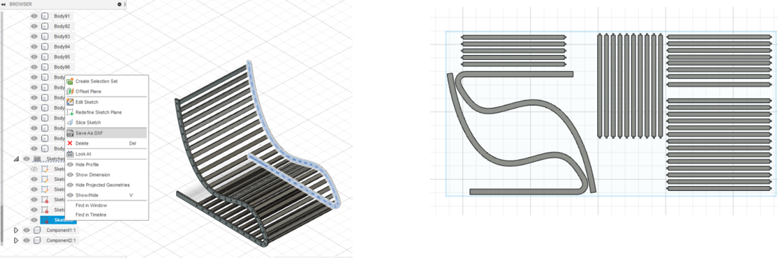
15- Now, the whole design is complete. It is now time to export it as dxf file, and I shared it to fablab email.
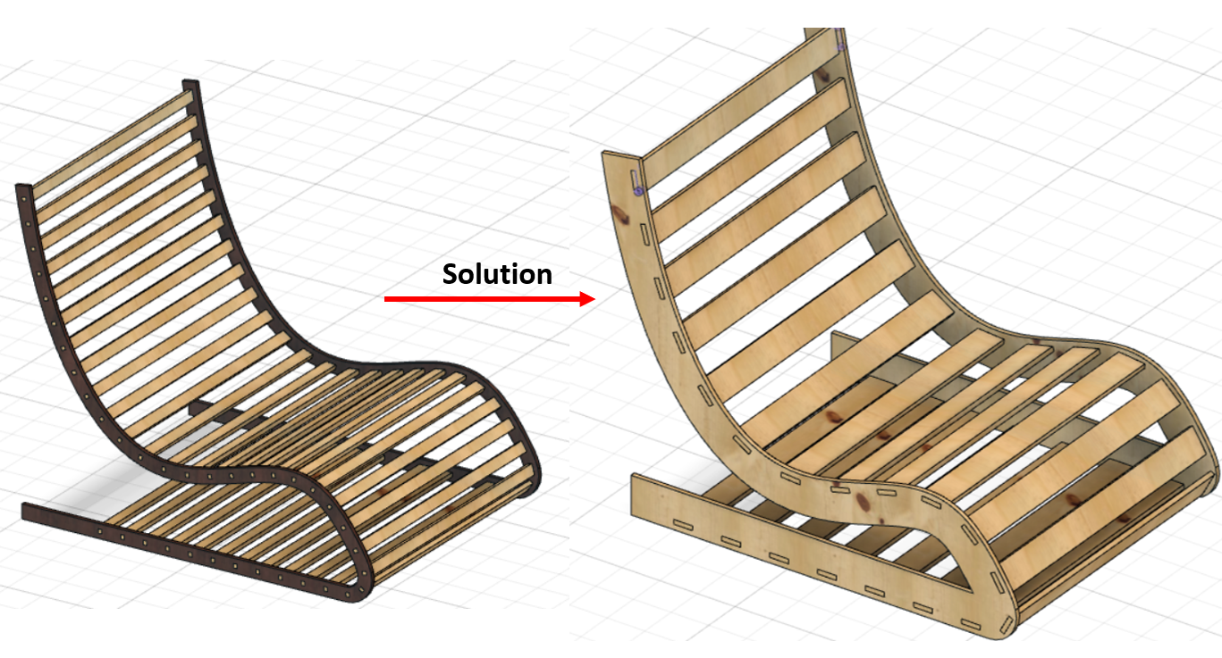
Structural stability dimensions
The final design looked weak, in terms of the thickness given to them, so I changed and increased their thicknesses, as well as reduced the middle portion pieces, and got the required result. The final dimensions are as follows:
A. Curve bodies of chair: From 4cm to 10cm now.
B. Middle portion: From 3cm to 7cm now.
C. Joint length: from 1cm to 5cm.
Problems I faced!
There are a number of problems I faced. They are:
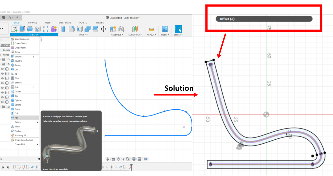
1- When I was following the chair tutorial, I made the curvy part of the chair as “Pipe”, which created a lot of difficulty in terms of extruding and offsetting it’s surfaces, so it took a really long time for me to figure it out. My instructor Haitham tried out many options to do the extruding, pulling etc. methods yet none worked.
Solution: With the idea of offset in mind, all thanks to my instructor, I made the sketch as Spline, and offset it as 3cm outside, finished the sketch, and extruded the sketch I made. The problem was solved.
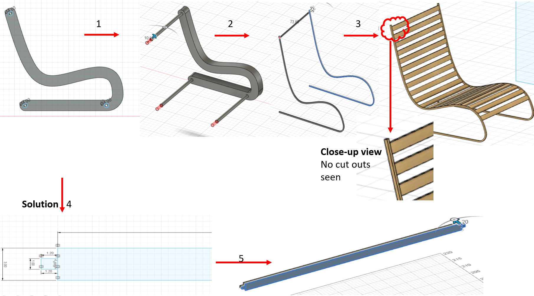
2- Another problem while following the tutorial was that, the middle portion of the chair (the horizontal lines), was becoming as “one body” with the curvy parts of the chair. I was not able to make it as a separate body, that could be edited. So, in order to combine it with curve, while making a joint hole in the curve, it took a lot of time to do it. Yet still in the end, I wasn’t able to do it.
Solution: After lots of trials, with the help of my instructor Duaa, I made the horizontal lines as separate body components. I made the side small rectangles and combined with the horizontal bodies, and extruded it to thickness of the wood (1.2 cm). I was able to attach it later to the curvy bodies, and combine and cut it.
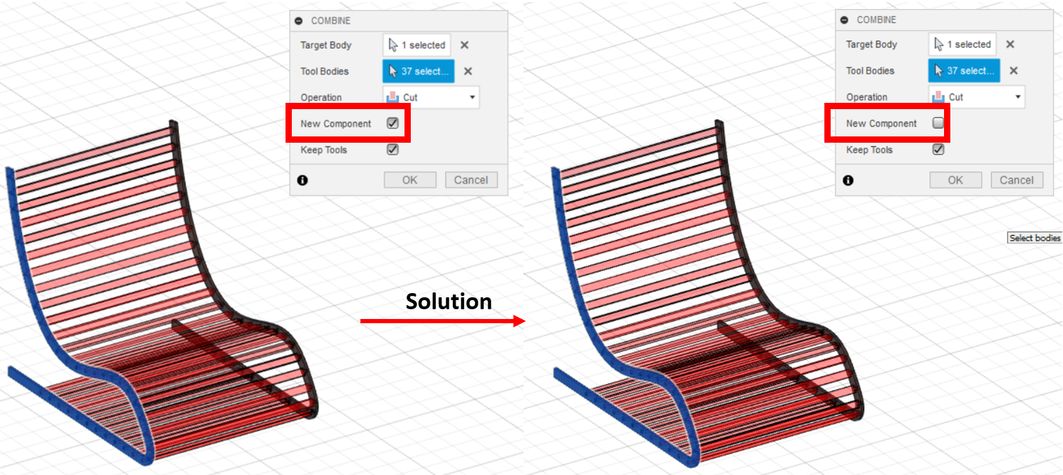
3- Another issue that happened, was that when I was combining the horizontal parts with the curvy bodies, I had selected the “new component” option in the COMBINE area. That’s the reason, when I tried to move the horizontal portion up to see the cut area on the curve, it didn’t show cut. Because it had made a new component there.
Solution: Before doing the same path for the horizontal bodies on the whole middle portion of chair, I tested the 1st horizontal body, by combining it with one curvy side of the chair, and cut it. In the options, I didn’t select the “new component” option, and clicked done. After moving the horizontal middle body up, I saw that there was now a cut seen in the curvy part of chair, indicating that it is now cutting the wood area of the curve.
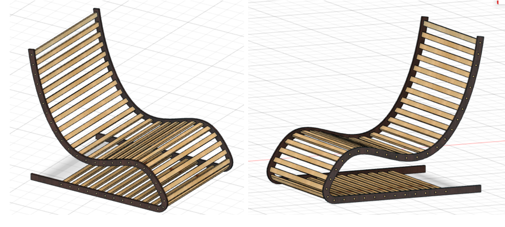
Final 3D look!
Cutting Phase!
Now, for the cutting phase, I tried to cut it using the software V-carve!
V-carve!
I went to V-carve website and downloaded the Free-trial application from it. However, my instructor Dua already had the software in her laptop, and she told me the step instructions for it.
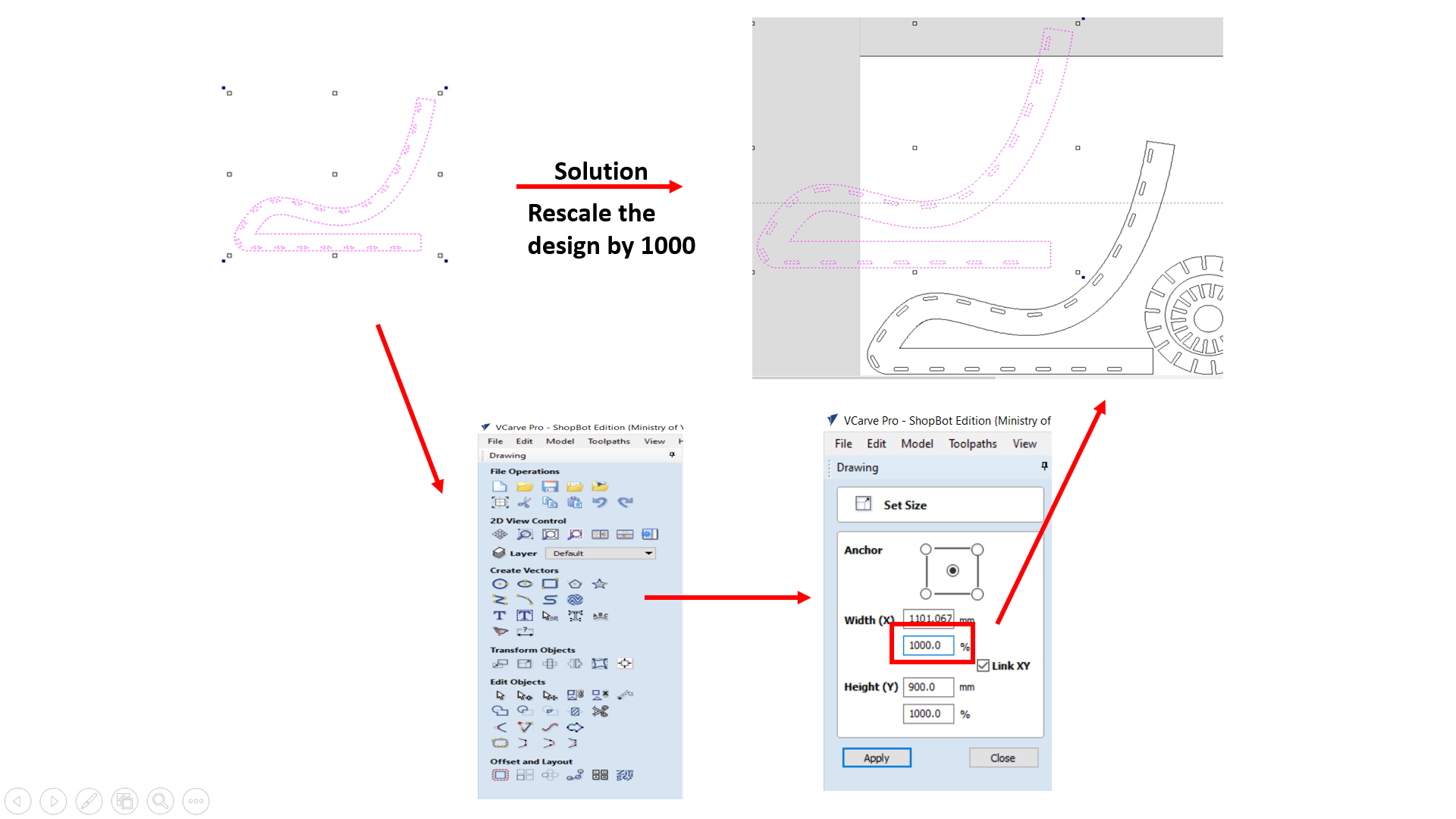
1- First, I imported my model in V-carve, but it seems the dimensions were in mm, and not in cm. So, we scaled the dimensions by 1000, and it became right.
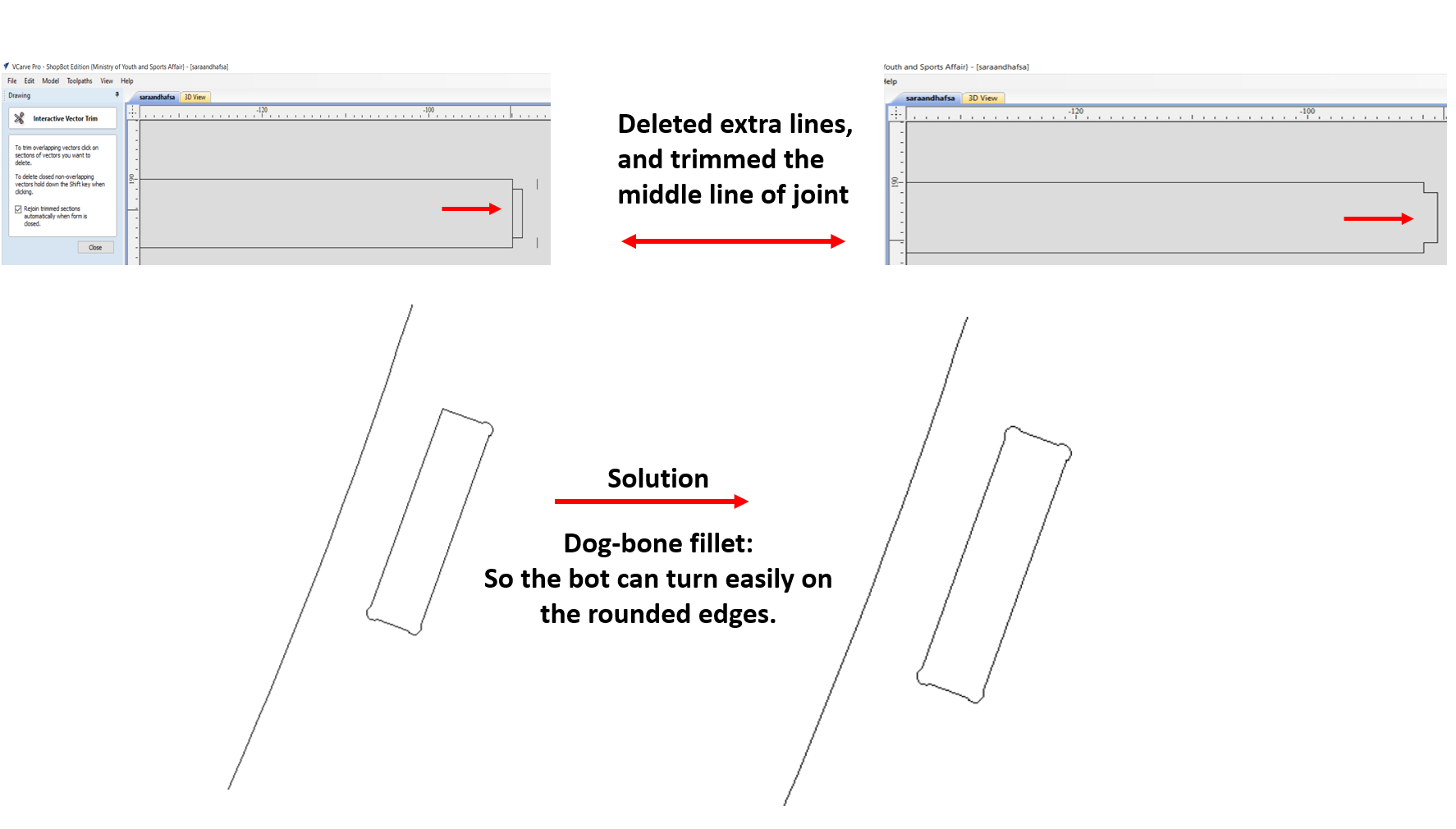
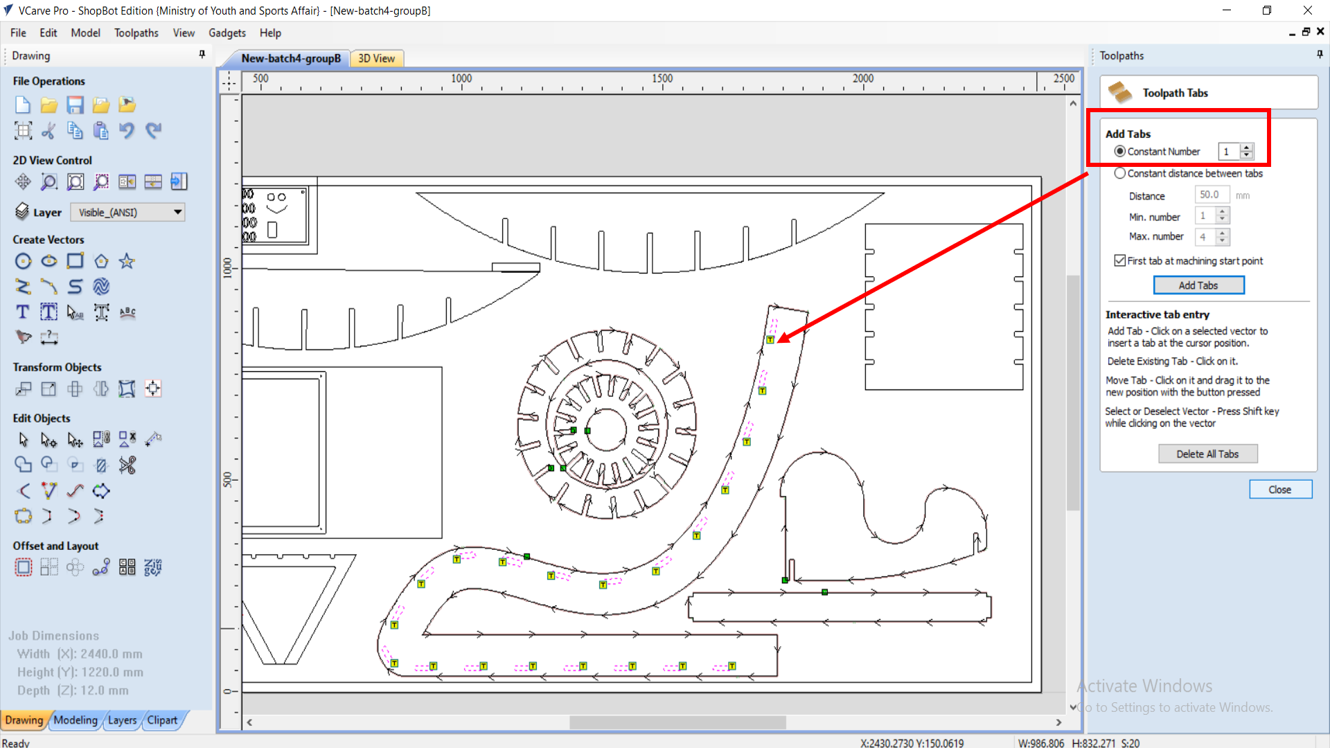
2- Next, there were some extra construction lines on the middle joint pieces, which were not needed. So, I deleted them, and trimmed the joint connection and connected the middle piece and joint together. After that, I chose the dog-bone fillet, so it creates a round on the egde of the hole, because the bot is a rounded 3mm shape, so when it turns, it won’t be a perfect 90 degree angle turn. That’s why the dog-bone fillet is used here.
3- Now, after doing all the changes, mine and one other colleague’s designs were put together to do a test check, before cutting all the other pieces.
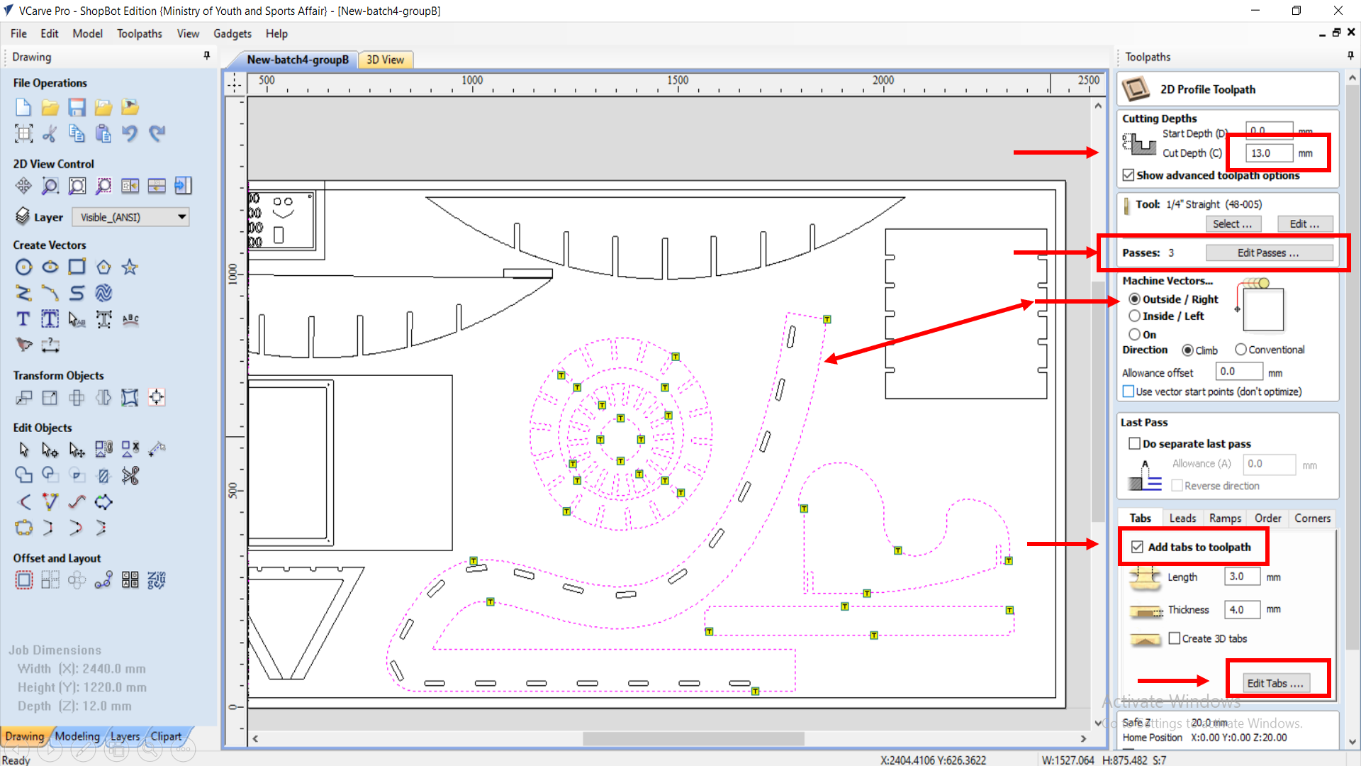
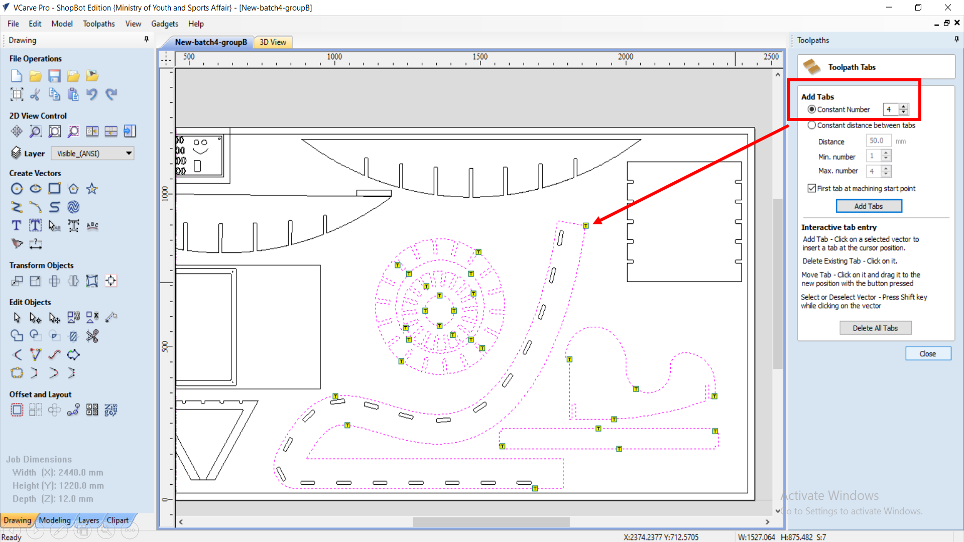
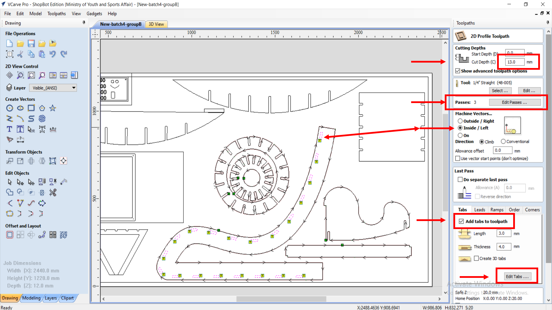
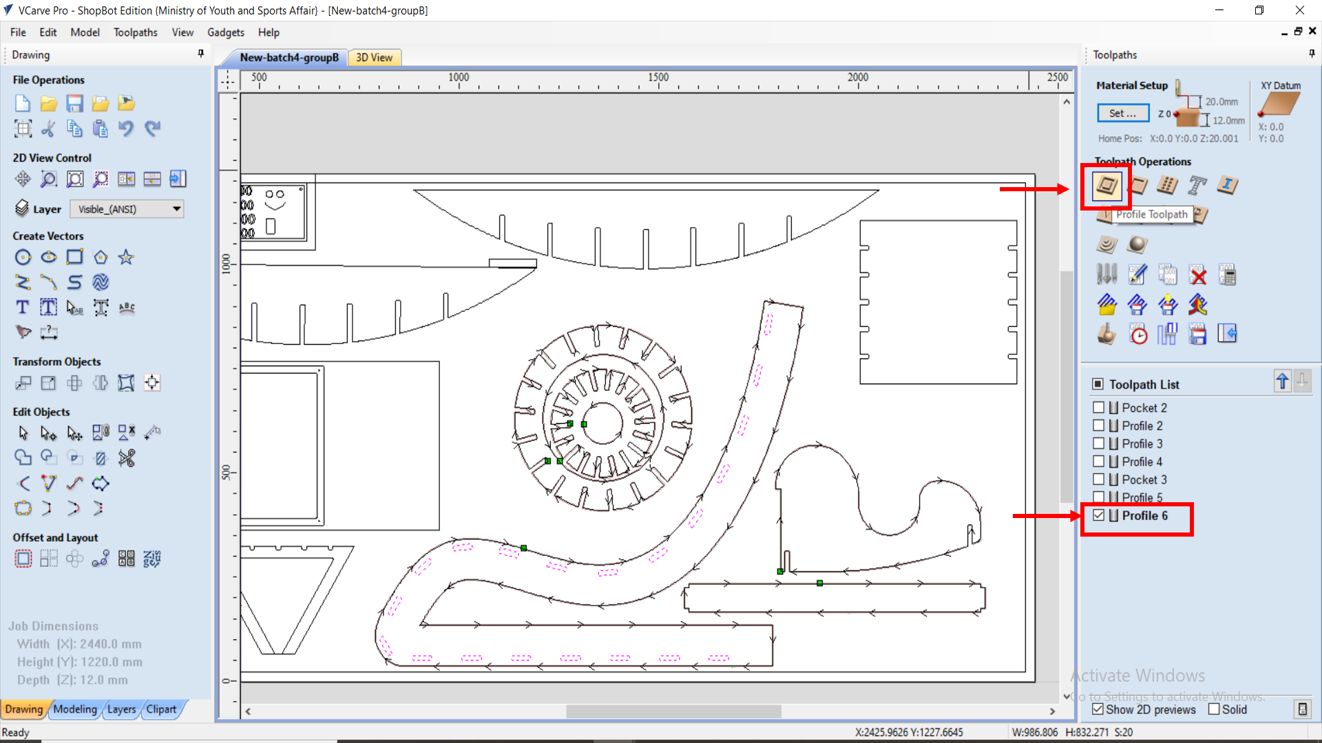
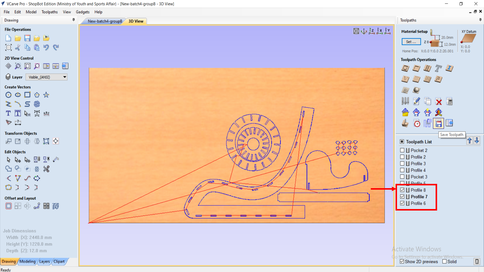
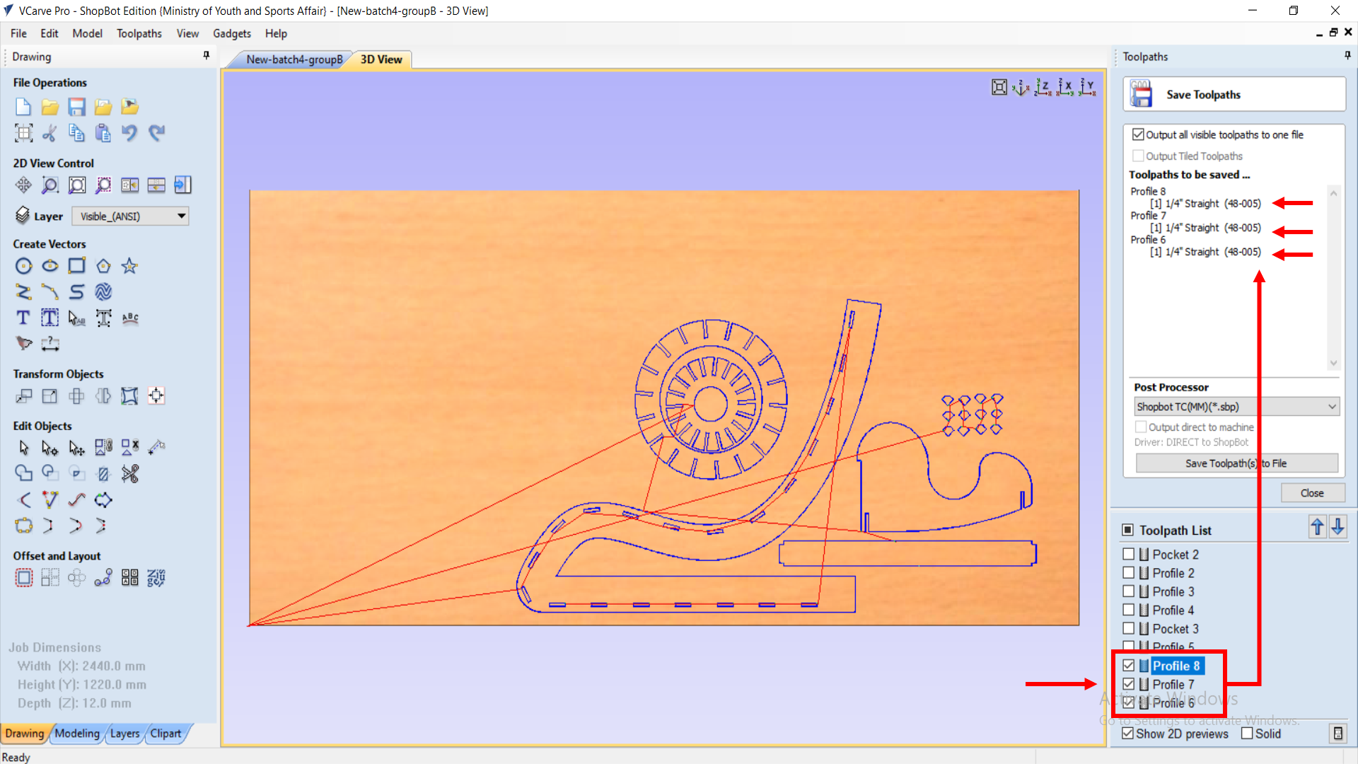
4- After doing all the following settings and editings, the final design was now sent to another software on PC, to start the CNC cutting.
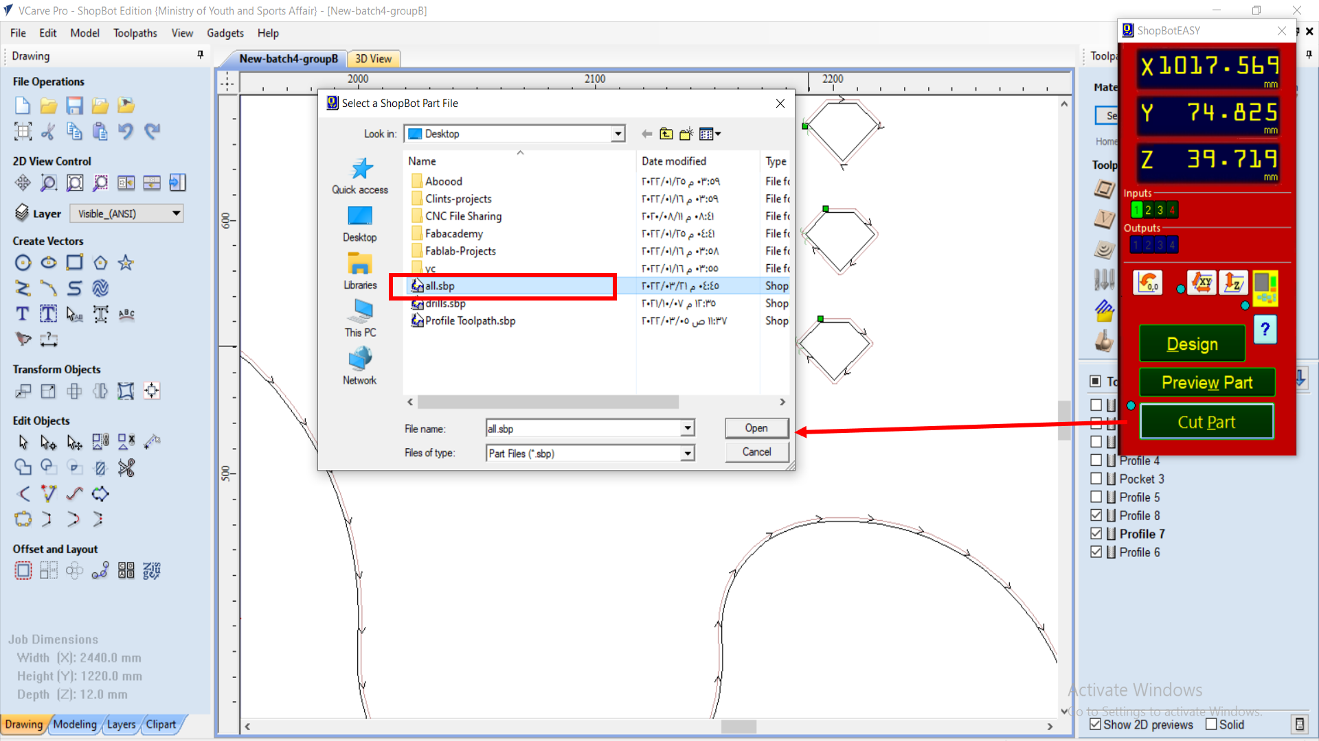
Pieces - Test Checking!
Now, we test out the pieces, and after about 40 minutes of cutting time, the pieces were ready to be tested and used.
Video!
After I got my pieces, I tried fitting both of them together, and they fitted just fine.
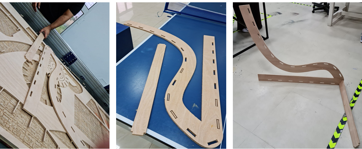
Final Pieces Assembly!
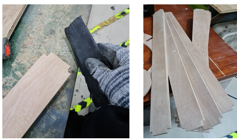
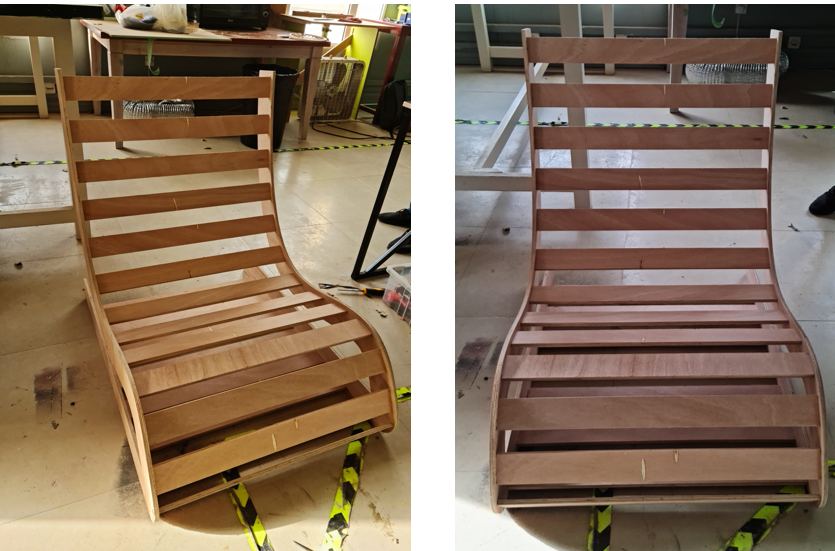
On the next day, my other horizontal pieces were finished cutting, and I started to assemble them in the already-started chair design.
However, the pieces were not fitting, so I had to sand-paper them before I fit them. So, I started sanding all of the wood pieces, I started the assembly again. They were still not fitting, so I had to use hammer to fit them down together. After 3 hours of work, I finally fitted them together, and now only one last piece is left to fit, and my chair design will be completed.
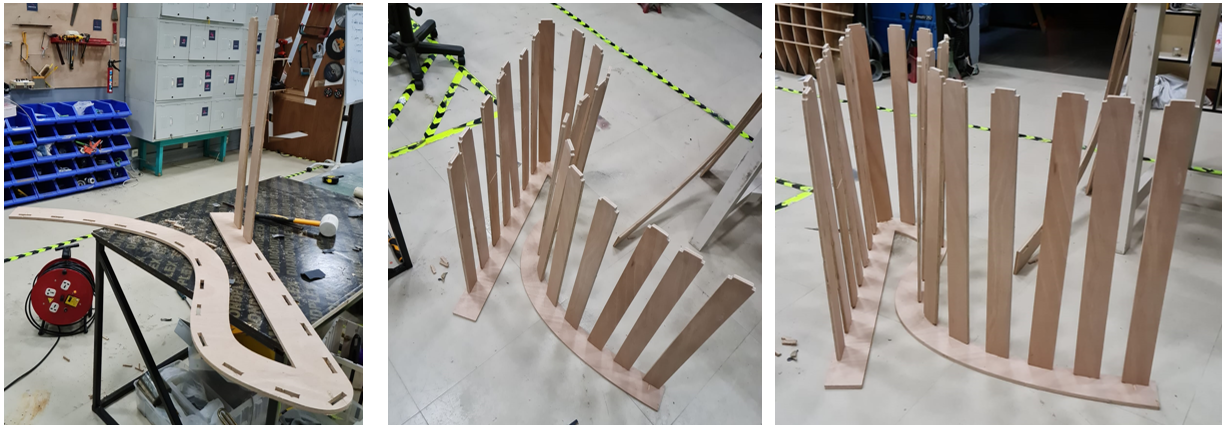
And then, I attached and fitted the final piece in the design, and Voila, my design is ready.
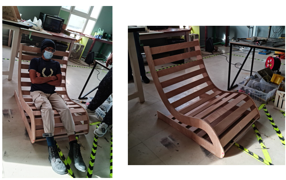
PROBLEM!
The mid-section of the wood piece is weak, in terms of structural support, so it breaks when someone tries to sit on it. I have to figure out a way to make it strong from the middle part, so it doesn’t break, and is actually usable.
DXF, F3d fusion360 Design Files!
Lounge Chair - Fusion 360 file