4. Embedded programming
This week, we were introduced to the topic of MicroControllers and their various types, along with their programming languages.
Tasks Overview
- GROUP ASSIGNMENT:
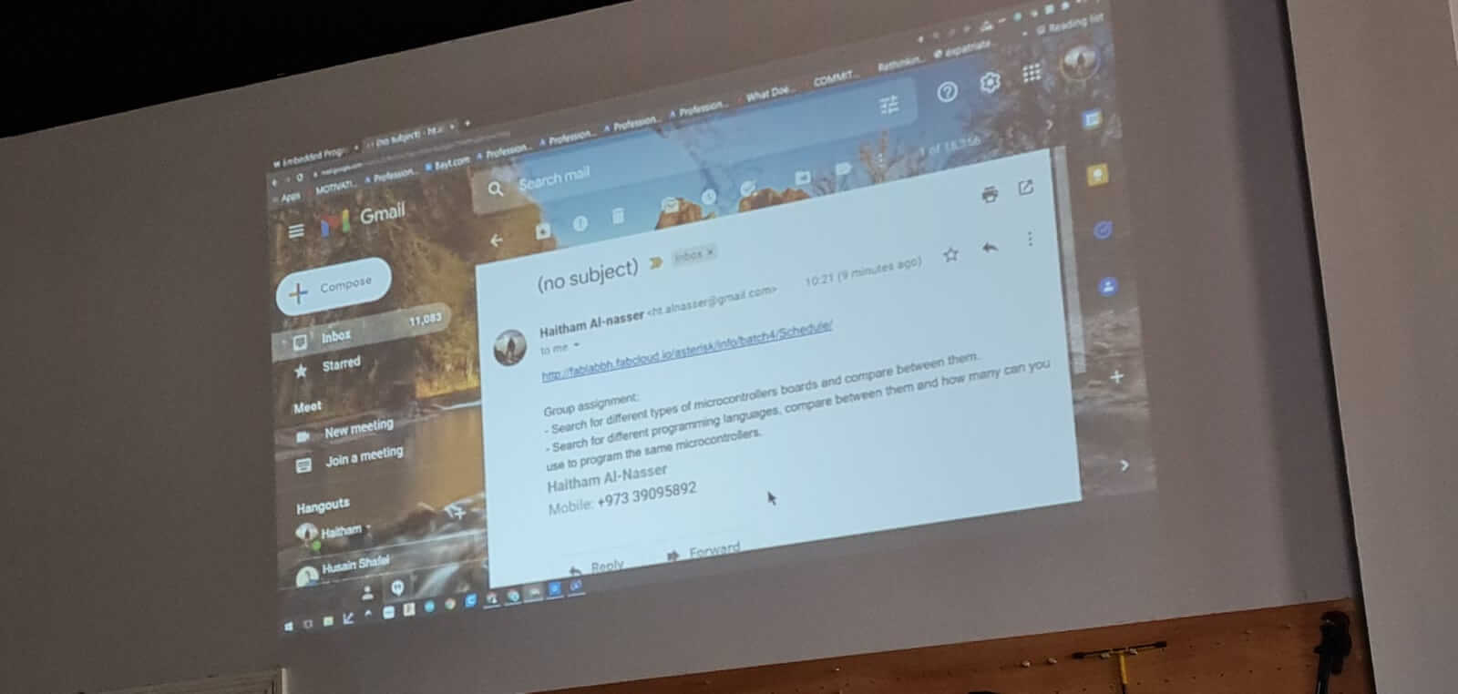
1- Search for different types of microcontrollers board and compare between them.
2- Search for different programming languages, compare between them and how many can you use to program the same microcontrollers.
- INDIVIDUAL ASSIGNMENT:
1- Read the datasheet for the microcontroller board you are programming.
2- Program the board you have to do something, with as many different programming languages and programming environments as possible. (two at least)
Embedded System
An embedded system is a small computer system, that is a combination of a computer processor, computer memory, and input/output peripheral devices. Its purpose is to control the device and to allow a user to interact with it. They tend to have one, or a limited number of tasks that they can perform.
What are Microcontrollers?
The microcontroller is like a brain. It’s a simple one IC (integrated circuit). To put simply, Micro controllers are responsible for controlling the circuit we have. Any System that has a remote controller mostly has a microcontroller in it. For example, controlling Phones, laptops, TV, PlayStation etc. etc.
Basically, Microcontrollers are those where we have to write a code stating its task and what it’s supposed to do and perform, by signalling voltage that flows in the circuit, similar to how our brain sends signals, to send blood to our body.
GROUP ASSIGNMENT
First, we were split in groups of 4, 3-4 members in each group, and tasks were divided among the groups. For my group, we were assigned to do the first task, i.e. to search for different types of Microcontroller boards, and to compare between them.
Group Work Link
The details for the group work documentation can be found on my colleague’s (Fatima) website: Fatima Mohamed’s Website
Group Assignment Part 01:
We found different types of Microcontrollers, such as Arduino, DIY Microcontroller Boards, Tennesy, BeagleBone Black Development Boards etc. We divided the different types among us, out of which I chose to study about the BeagleBone Black Development Board.
The BeagleBone Black Development Board
BeagleBone Black is a small package of a microprocessor and memory which helps to operate the other embedded system through a Linux operating system.
It is widely used in automation, IoT and robotic at the development level.
• It comes with built-in wireless networking functionality, it can be accessed remotely over the internet and can be used to access electronic projects.
• BeagleBone Black is really a cheap, community-supported development platform for embedded program developers.
• Booting time to install Linux requires TEN seconds and get started on development in under 5 minutes using only a sole USB cable.
How do I program my BeagleBoard?
• Beagleboard: C/C++ Programming.
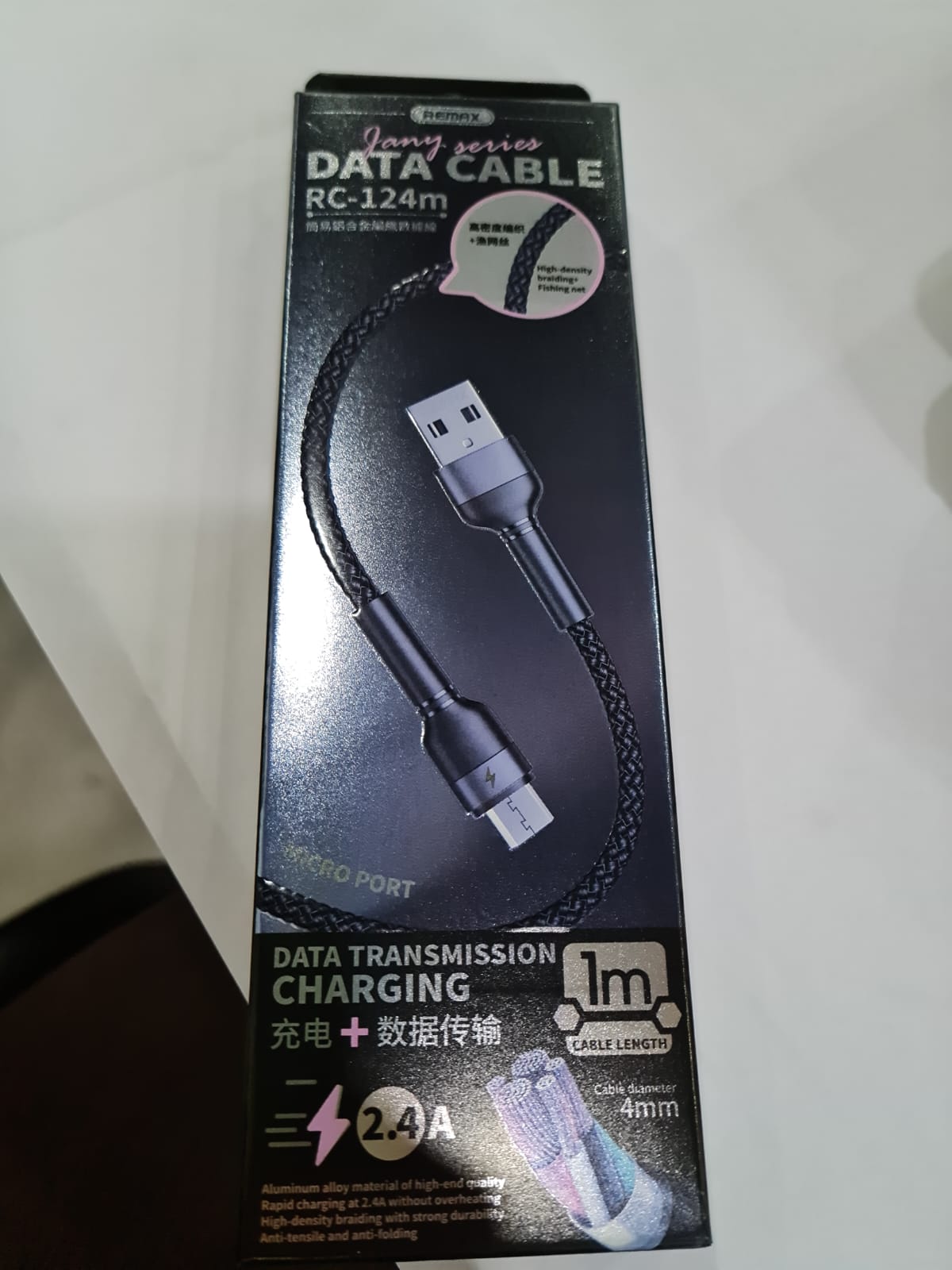
• 1) Connect your BeagleBone to your computer using a Mini-USB Data Cable.
• 2) Using a terminal shell, such as PuTTy, serial connect into your BeagleBone and log in as ‘root’.
• 3) Now, we will create a simple C program that turns an on-board LED on and off ten times. Type this into your terminal shell.
Power Inputs
BeagleBone Black has two power inputs, one is through a DC power Jack input port and the second one is USB. Both ports have different power input ratings.
Power Outputs
Beagle Bone has three power output pins; these pins can be used to give powers to external devices.
-
The first pin gives 3Volts and its power comes directly from LDO (Low Dropout) and it can be used for maximum 250mA current rating devices.
-
The second power port gives 5 volts output and it comes directly from the DC Jack power supply pin. There won’t be any power on this pin when the device will be operated with a USB power pin. The current on this pin will be dependent on the DC power input but it will be limited to 1000mA.
-
The third power port uses a regulator and it comes from both USB and DC power. The voltage on this pin will be 5 volts but the current will depend on the power input.
Further details and references could be found by the following websites:
BeagleBone Black Pinout datasheet
Types of Microcontroller Boards And their Applications
BeagleBone Black Pinout, Pin Configuration and Features
Group Assignment Part 02:
We exchanged information with the other groups, and this is what we received, in terms of different programming langauges.
This image is referenced from my colleague Mohammed Alghazali’s website
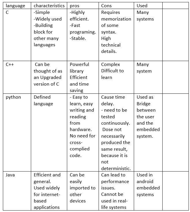
Further information regarding the programming languages could also be found at my colleague’s (Zainab Abbas) website: Zainab Abbas
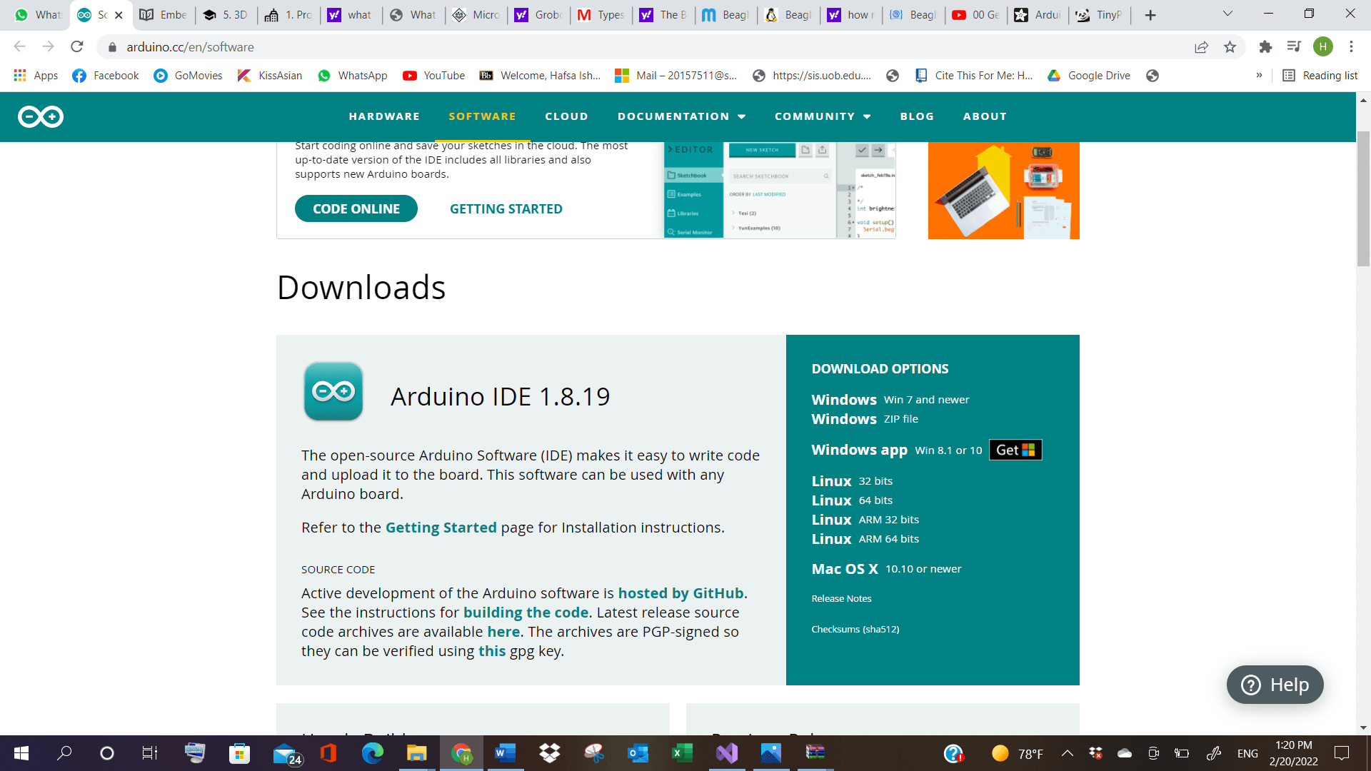
ARDUINO Software
We were asked to download the software, called Arduino. After downloading it, another link was shared, to follow instructions for the installation of the microcontroller boards.
Click here to download Arduino Software
click here to see instructions for setting the boards in the app
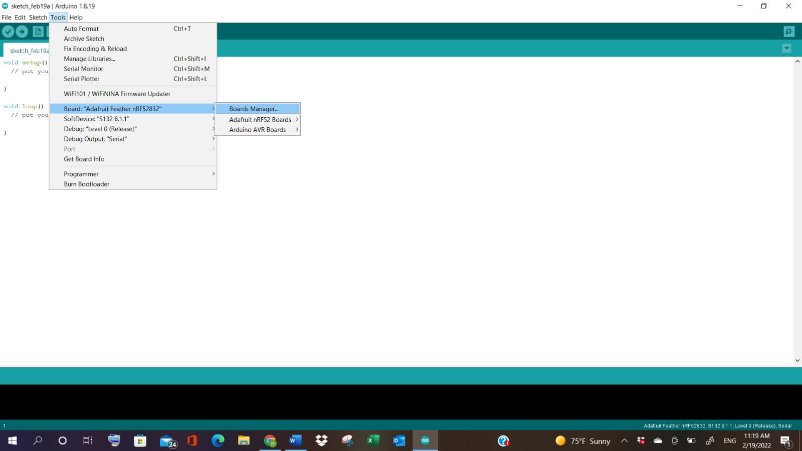
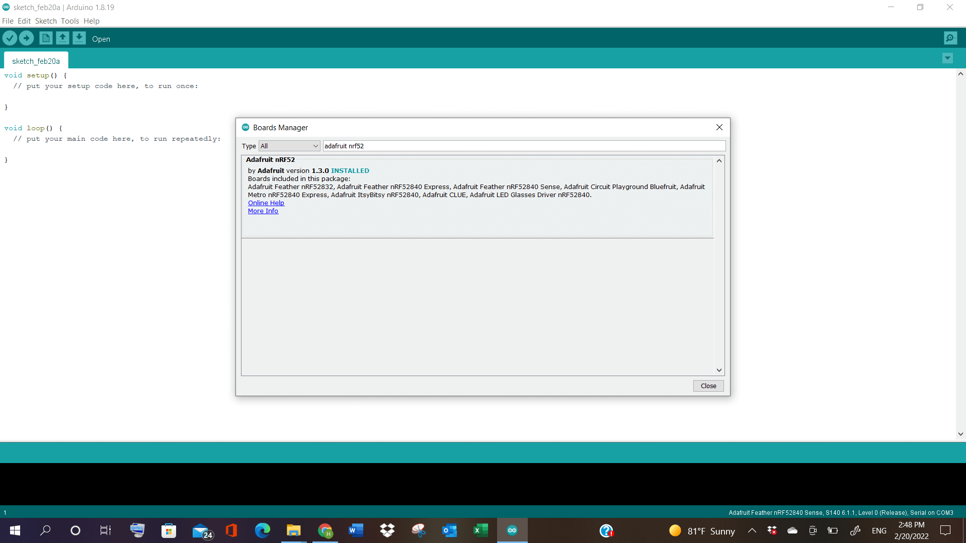
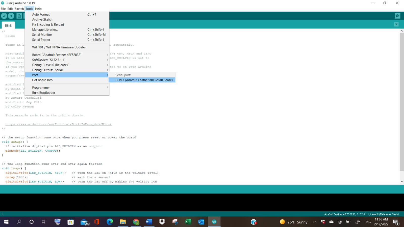
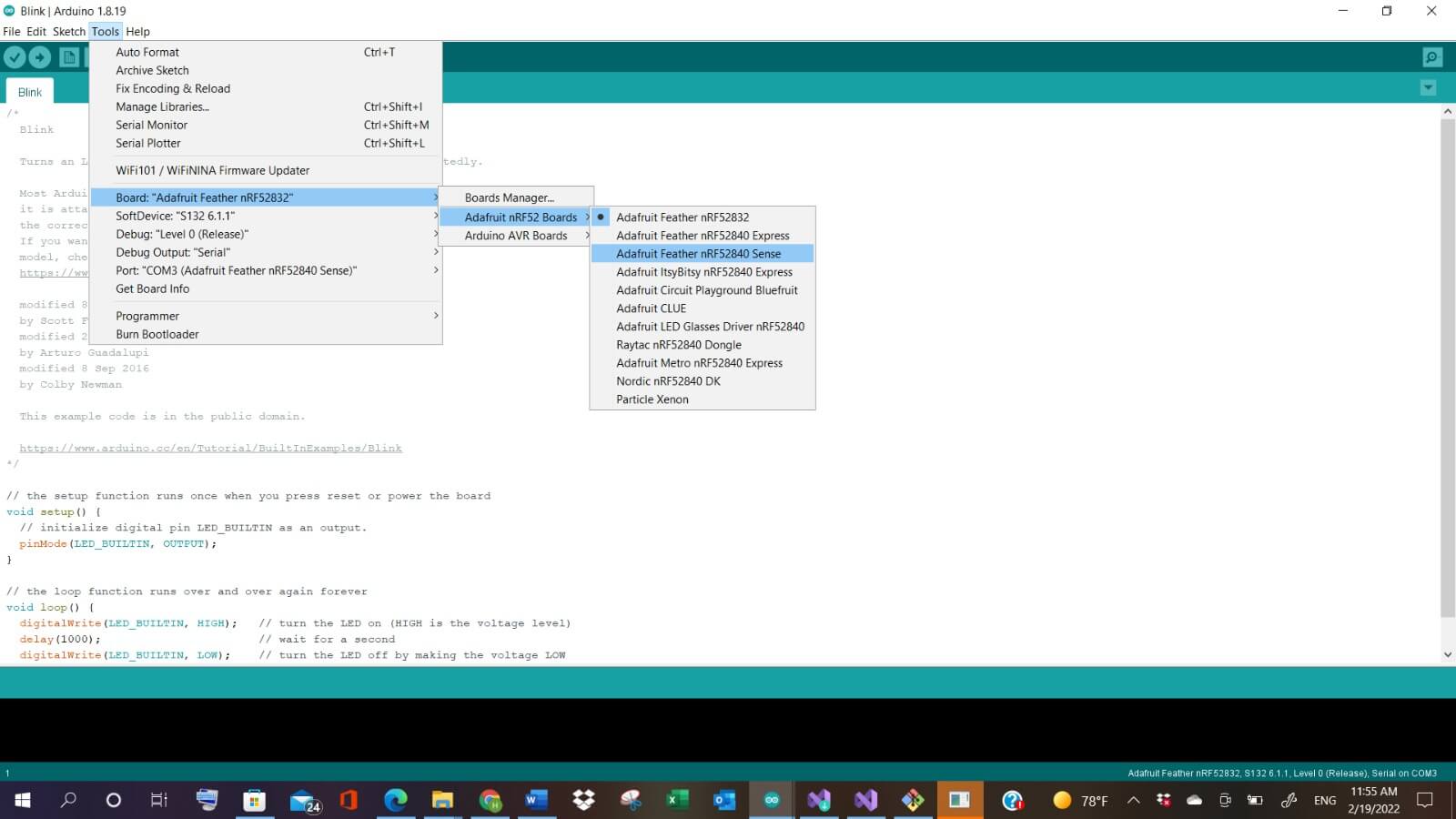
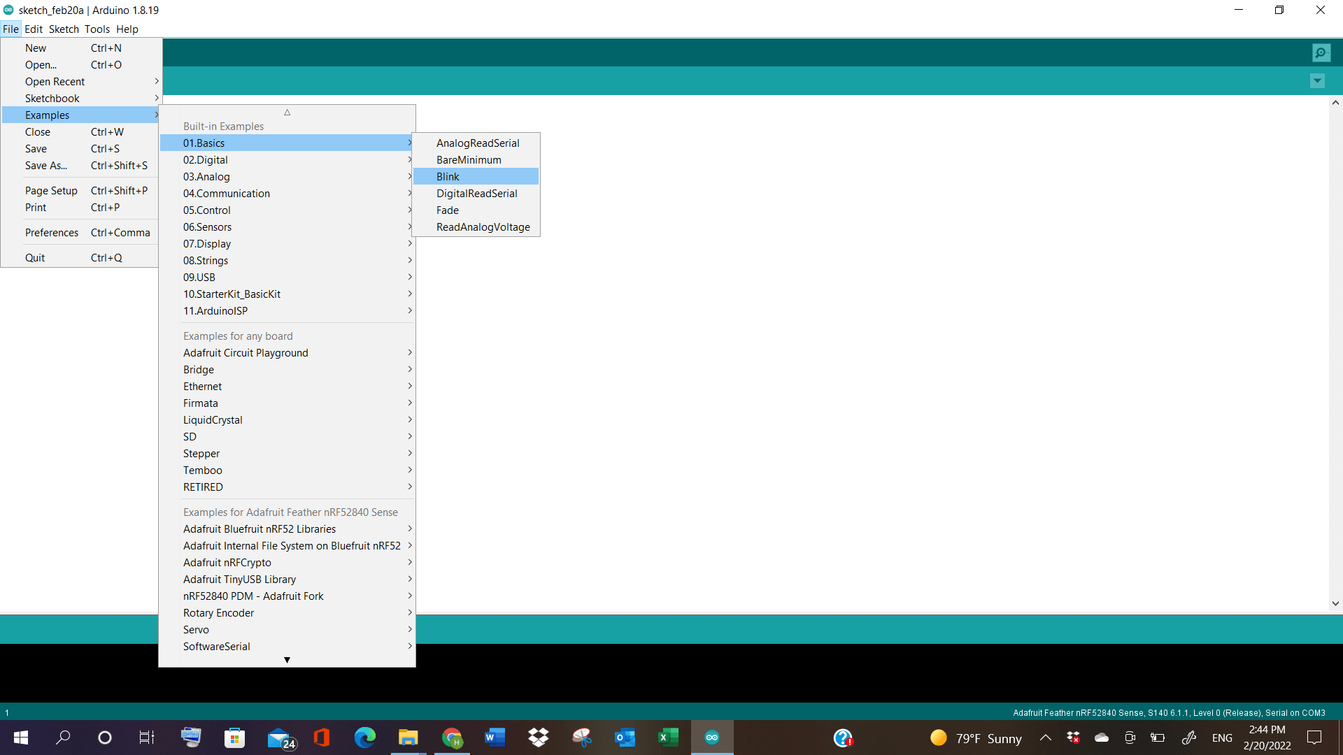
After Setting up the app, and following the board manager setup steps, I downloaded the Arduino Adafruit from the Board Managers. Later, connecting the USB with the microcontroller board, I went to File>Examples>1.Basic>Blink.
BLINK PROGRAMMING
The blink program, in arduino, uses the LED, which is built into Maker Board, to flash on and off. And this is done by giving the values in the program, which results in different blinking periods of LED light, in the board.

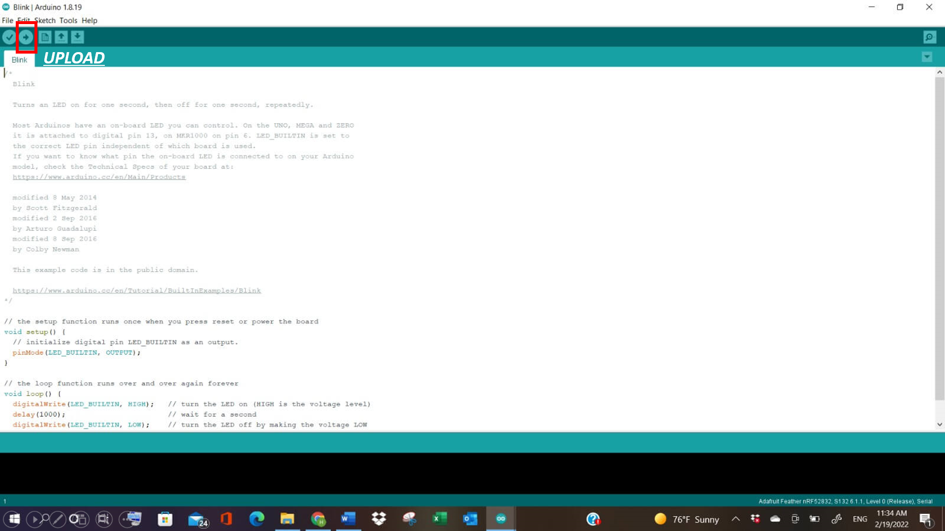
After setting it to Blink, the timing was measured in the board, specifically the red light. It depends on the number mentioned in “delay” in the bottom of the blink page. When changing it, the red blinking on the board changes too.
Video
TIP
In order to start simulation and upload the new information again, click on the following Reset button twice. It will reset the port, and then we can start the simulation again, by clicking on the “Upload” option, shown in the blink, in the top left corner.
CHALLENGE TIME!!
TINKERCAD
TinkerCad is a 3D modelling program, where aside from it’s 3D designs - circuits and codeblocks are also programmed and designed in it.
Click here to see TINKERCAD site
Upon starting Tinkercad, I started exploring its different components like “Input”, “Output”, “Math” etc. etc.
Now, for the challenge, we are asked to write any random word, and decipher it’s code, by knowing the following:
- ”-” is one second (1)
- ”.” is half second (0.5 second)
- Space between “2 dashes” or “2 dots” is (0.25) seconds
- Space between “one letter” and the “other” is 2 seconds.
FUNCTION BLOCK PROGRAMMING
This is another type of programming, apart from Blink, where we add the codes, deriving it from the morse code translator, and then adding it in the circuit.
Morse Code Translator
Click here to see Morse Code Translator
Morse code is a method used in telecommunication to encode text characters as standardized sequences of two different signal durations, called dots and dashes.
By understanding this whole process, I started working on a small random word, such as “HI”.
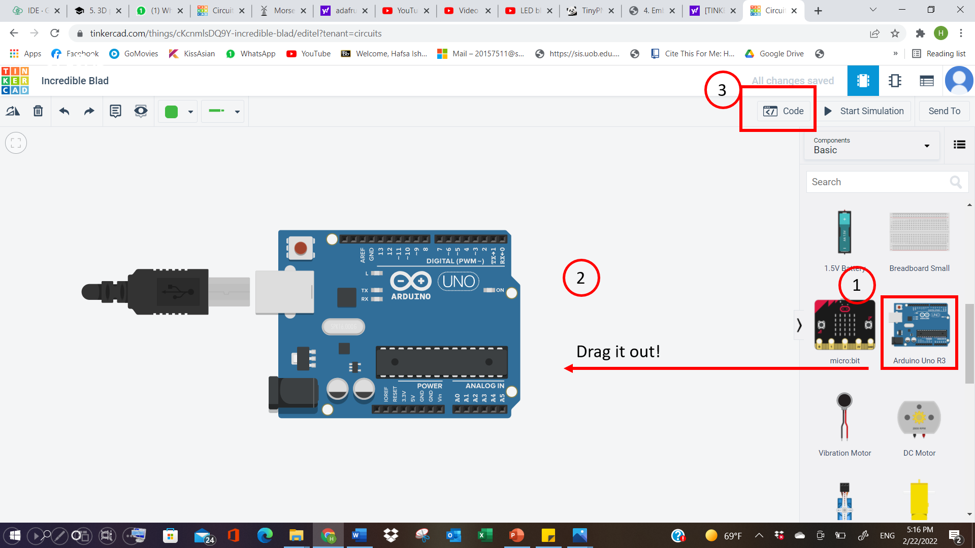
I went to TINKERCAD, and selected “Circuits” in it. Then dragged Arduino uno R3 outside to the left page, and then clicked on “Code”.
Here, I started giving the codes, keeping in mind the “different second” differences between each letters or words.
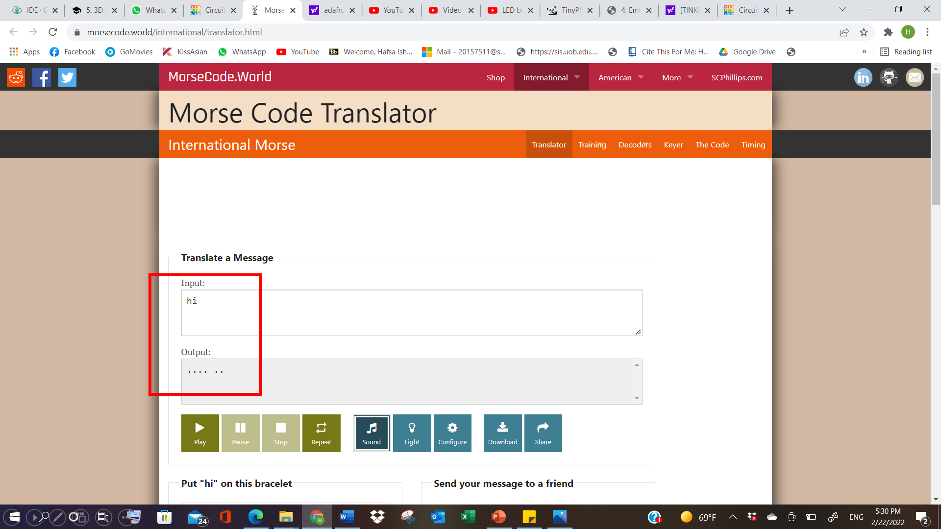
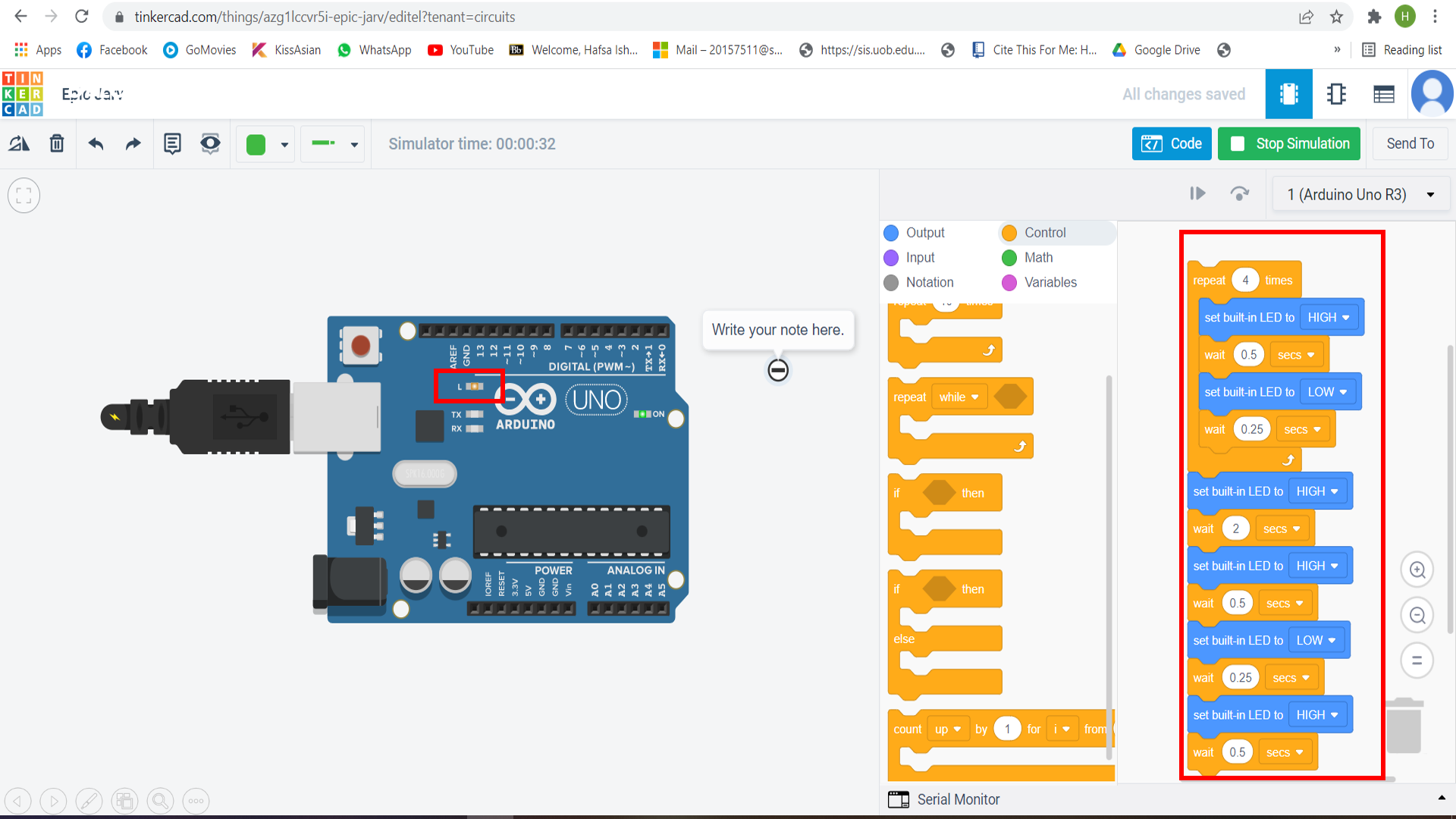
And then, the LED started blinking, showing the different delay periods of the light, by taking into account the seconds, listed in the code.
Code for the word: “Hi”
// C++ code
//
void setup()
{
  pinMode(LED_BUILTIN, OUTPUT);
}

void loop()
{
  digitalWrite(LED_BUILTIN, HIGH);
  delay(500); // Wait for 500 millisecond(s)
  digitalWrite(LED_BUILTIN, LOW);
  delay(250); // Wait for 250 millisecond(s)
  digitalWrite(LED_BUILTIN, HIGH);
  delay(1000); // Wait for 1000 millisecond(s)
  digitalWrite(LED_BUILTIN, LOW);
  delay(250); // Wait for 250 millisecond(s)
  digitalWrite(LED_BUILTIN, HIGH);
  delay(500); // Wait for 500 millisecond(s)
  digitalWrite(LED_BUILTIN, HIGH);
  delay(2000); // Wait for 2000 millisecond(s)
  digitalWrite(LED_BUILTIN, HIGH);
  delay(500); // Wait for 500 millisecond(s)
  digitalWrite(LED_BUILTIN, LOW);
  delay(250); // Wait for 250 millisecond(s)
  digitalWrite(LED_BUILTIN, HIGH);
  delay(1000); // Wait for 1000 millisecond(s)
  digitalWrite(LED_BUILTIN, HIGH);
  delay(2000); // Wait for 2000 millisecond(s)
  digitalWrite(LED_BUILTIN, HIGH);
  delay(500); // Wait for 500 millisecond(s)
  digitalWrite(LED_BUILTIN, LOW);
  delay(250); // Wait for 250 millisecond(s)
  digitalWrite(LED_BUILTIN, HIGH);
  delay(500); // Wait for 500 millisecond(s)
  digitalWrite(LED_BUILTIN, HIGH);
  delay(2000); // Wait for 2000 millisecond(s)
  digitalWrite(LED_BUILTIN, HIGH);
  delay(1000); // Wait for 1000 millisecond(s)
  digitalWrite(LED_BUILTIN, LOW);
  delay(250); // Wait for 250 millisecond(s)
  digitalWrite(LED_BUILTIN, HIGH);
  delay(500); // Wait for 500 millisecond(s)
}
INDIVIDUAL ASSESSMENT
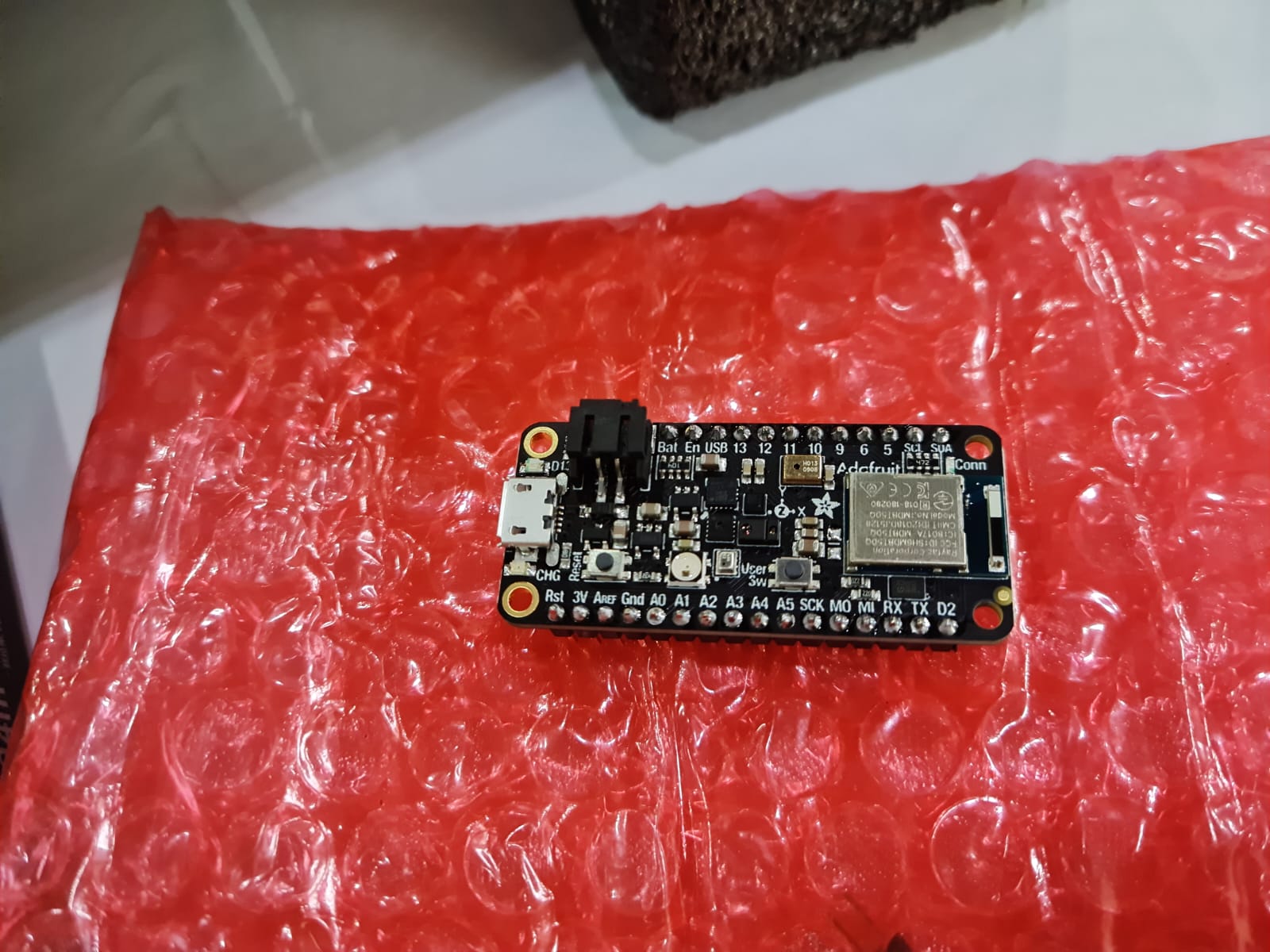
Part 01: Reading ADAFRUIT datasheet
Here, the important information about the adafruit datasheet is collected, by looking at the following website:
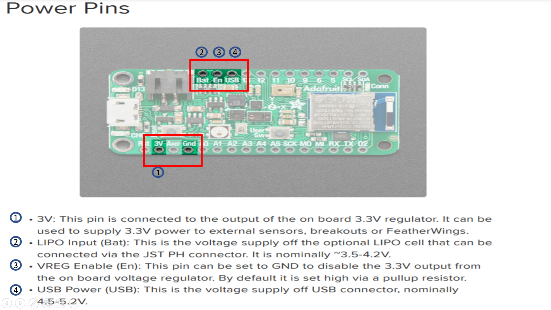
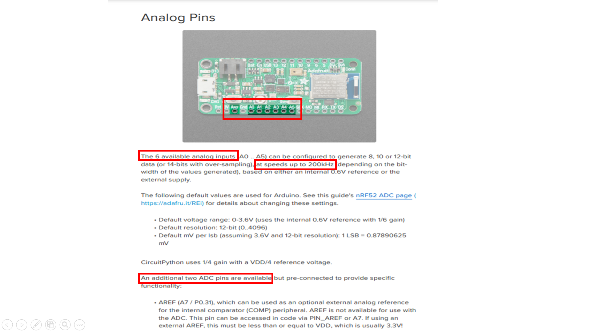
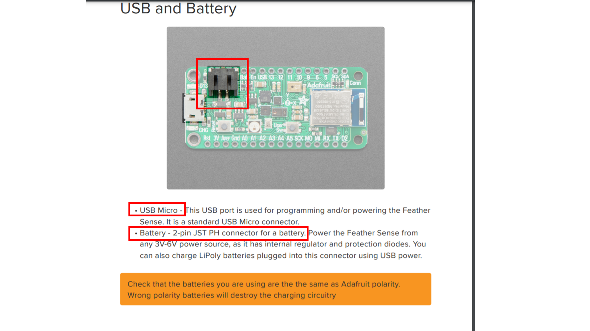
POWER PINS & ANALOG PINS:
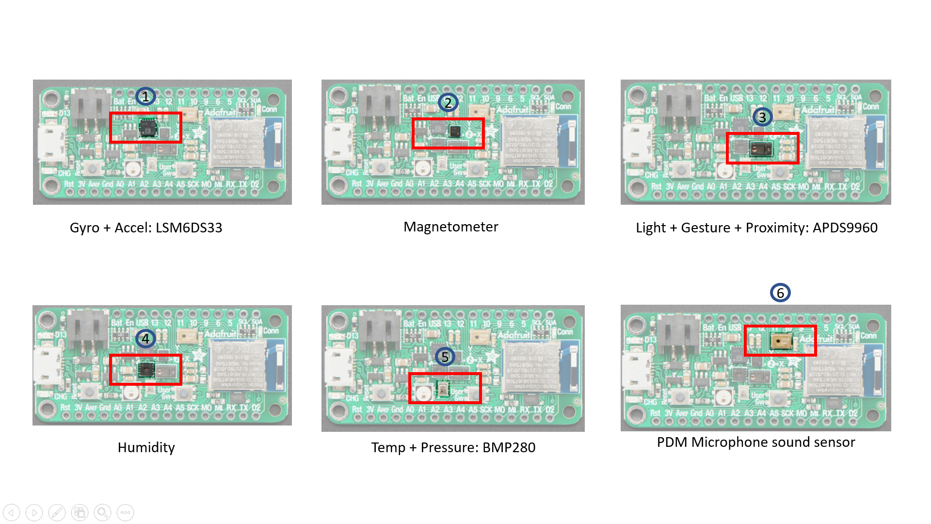
SENSORS:
There are several types of sensors integrated in the microcontroller, including:
-
Gyro + Accel: LSM6DS33, which is an accelerometer + gyroscope. The 3-axis accelerometer, can tell you which direction is down towards the Earth (by measuring gravity) or how fast the Feather Sense is accelerating in 3D space.
-
Magnetometer: LIS3MDL, which sense the magnetic fields that surround us. Magnetometers can sense where the strongest magnetic force is coming from, generally used to detect magnetic north, but can also be used for measuring magnetic fields.
-
Light + Gesture + Proximity: APDS9960, - Detect simple gestures (left to right, right to left, up to down, down to up are currently supported), return the amount of red, blue, green, and clear light, or return how close an object is to the front of the sensor.
-
Humidity: SHT30, This sensor has an excellent ±2% relative humidity and ±0.5°C accuracy for most uses. Sensor is I2C on standard pins, address 0x44.
-
Temp + Pressure: BMP280, This sensor is a precision sensing solution for measuring barometric pressure with ±1 hPa absolute accuracy, and temperature with ±1.0°C.
-
PDM Microphone sound sensor: MP34DT01-M - PDM sound sensor.
BUTTONS:
-
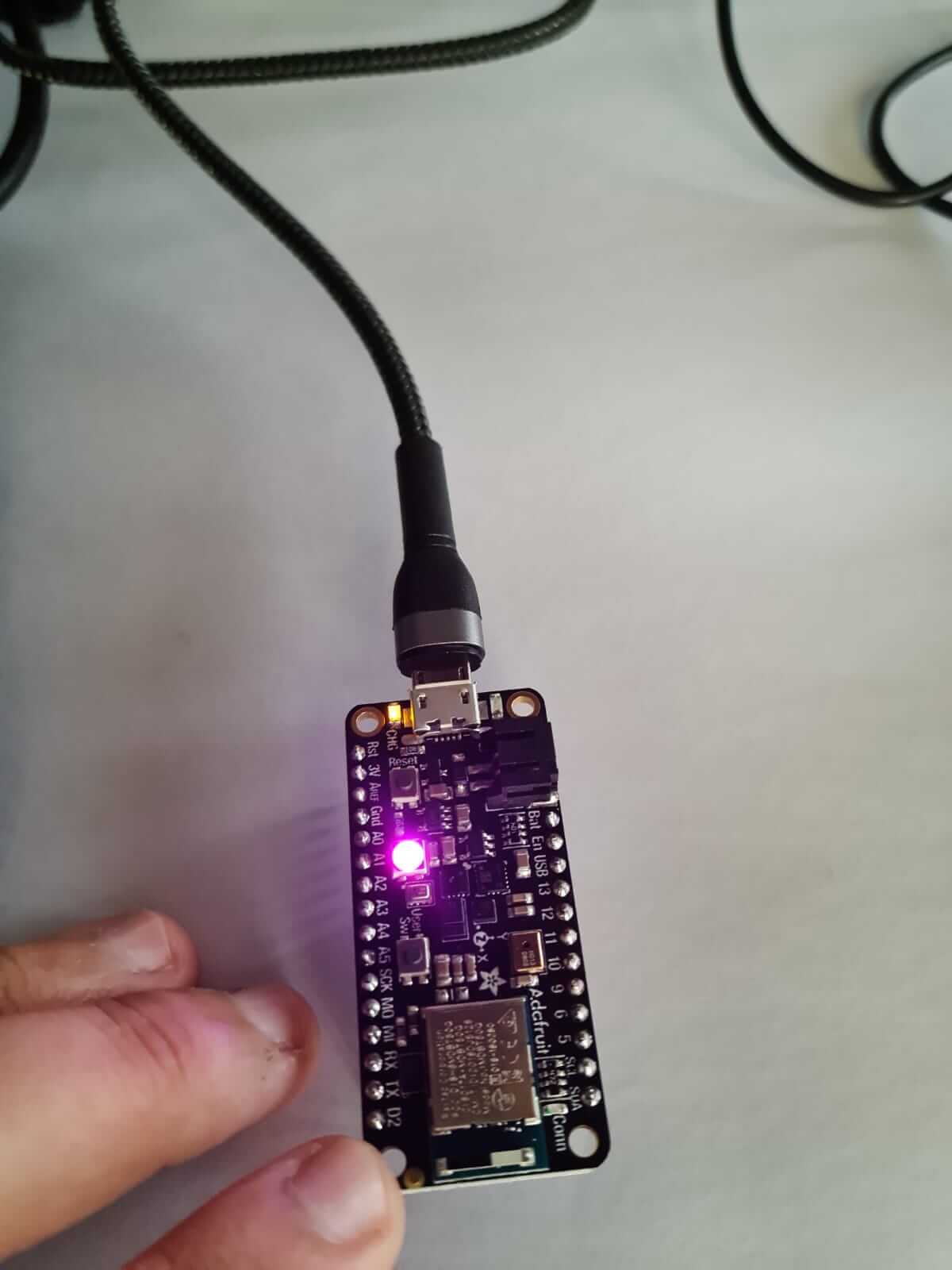
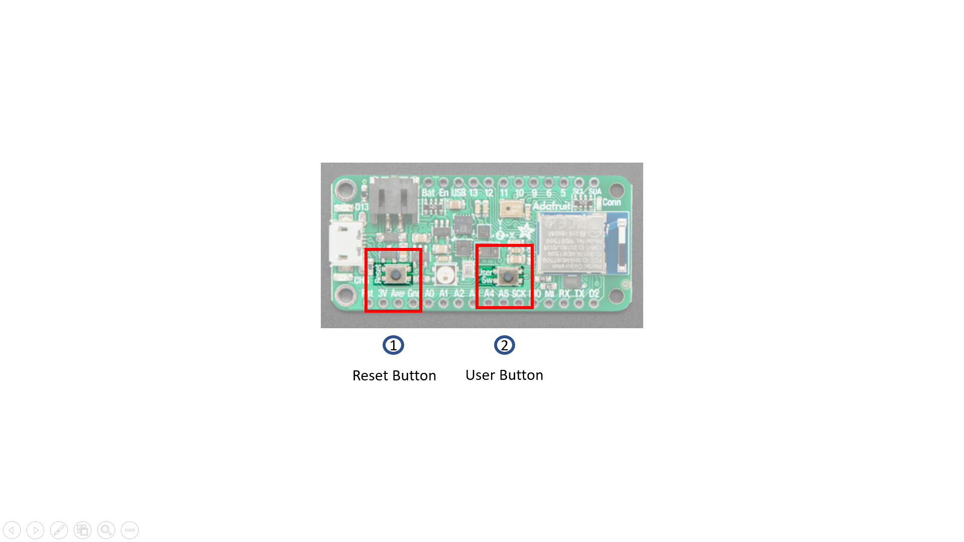
Reset button: The button on the left next to the USB connector resets the board. Press once to reset. Quickly press twice to enter the bootloader.
-
User button: The button on the right is both usable by the bootloader and usercontrollable. Address it in code using board.SWITCH in CircuitPython and D7 in Arduino.
NEOPIXEL & STATUS LEDs:
NeoPixel - The addressable RGB NeoPixel LED is used as a status LED by the bootloader and CircuitPython, but is also controllable using code. Control it using board. NEOPIXEL in CircuitPython and D8 in Arduino.
Red status LED - This little red LED, labeled D13, works as a status LED in thebootloader. Otherwise, it is controllable using code by addressing board.RED_LED in CircuitPython, and D13 in Arduino.
Blue status LED - This little blue LED, labeled Conn, works as a connectivity status LED in Arduino, and is user-controllable in both Arduino and CircuitPython. Control it in code by addressing board.BLUE_LED in CircuitPython and D4 in Arduino.
Charge status LED - The little LED, labeled CHG, below the USB connector is the charge status LED. When no battery is connected, it flashes. When a battery is connected and charging, the LED is steady amber.
By seeing the different pins and their voltages, and the LEDs, it can be seen how the microcontroller board works, and how each pin has a specific funcition to it, which it performs, when it is uploaded with the desired informational values.
Part 02: Modes
In part 2, we were given 3 modes, and we had to choose one of them.
EASY MODE: Blink your led but have your blink delay periods be randomized values between 1 second and 5 seconds . MEDIUM MODE: Pre code your microcontroller to send a Morse code 1 word message and challenge a friend, family member, your colleagues or your instructor to figure it out. dot = 0.5 second light on. dash=1 second light on. gap between dots and dashes=0.5 second light off. gap between letters=2 second light off.
HARD MODE: You select the duration of the light being on and off while the program is running by entering it in the serial monitor. Write a code that takes the data from the serial monitor and delays by that amount of time.
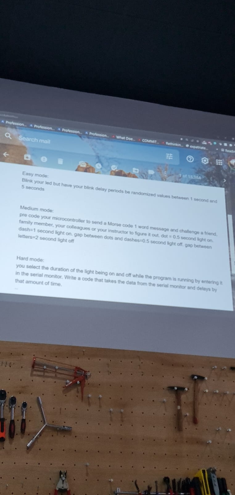
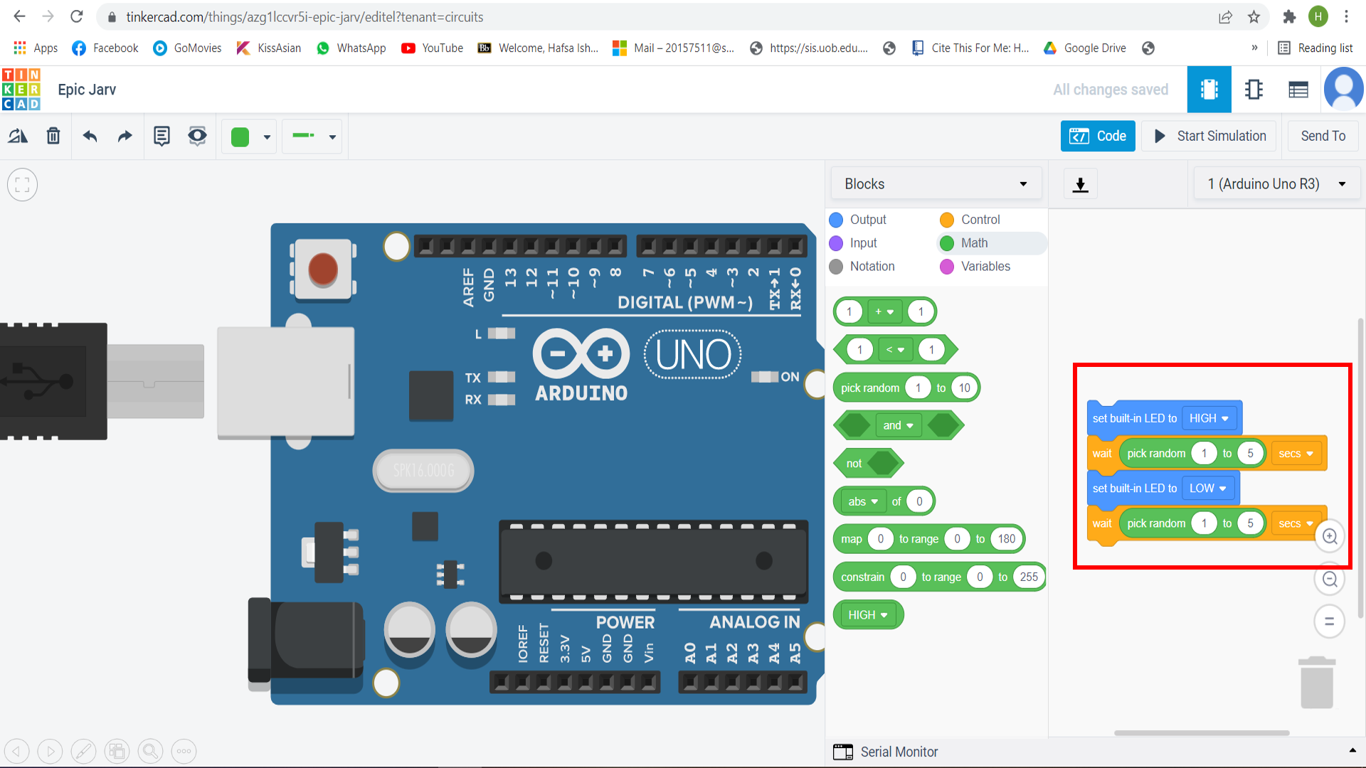
I chose the EASY MODE, which was to: Blink your LED but have your blink delay periods be randomized values between 1 second and 5 seconds.
I went to the tinkercad circuit, and made the code there, by setting the Set Built-in LED to High and Low, and added the wait seconds from “Control”. Now for the randomised values, I went to the “Math” section, and selected “Pick random 1-10”, and brought it to right screen. I attached it with the “Wait seconds”, and gave the values of “1-5”.
These random values would let the LED blink in a randomised way, ranging from 1-5. The method is totally random, and so is the blinking.
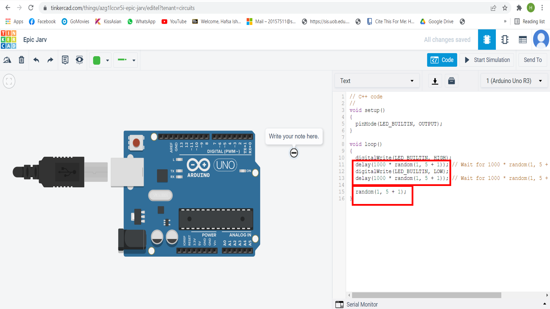
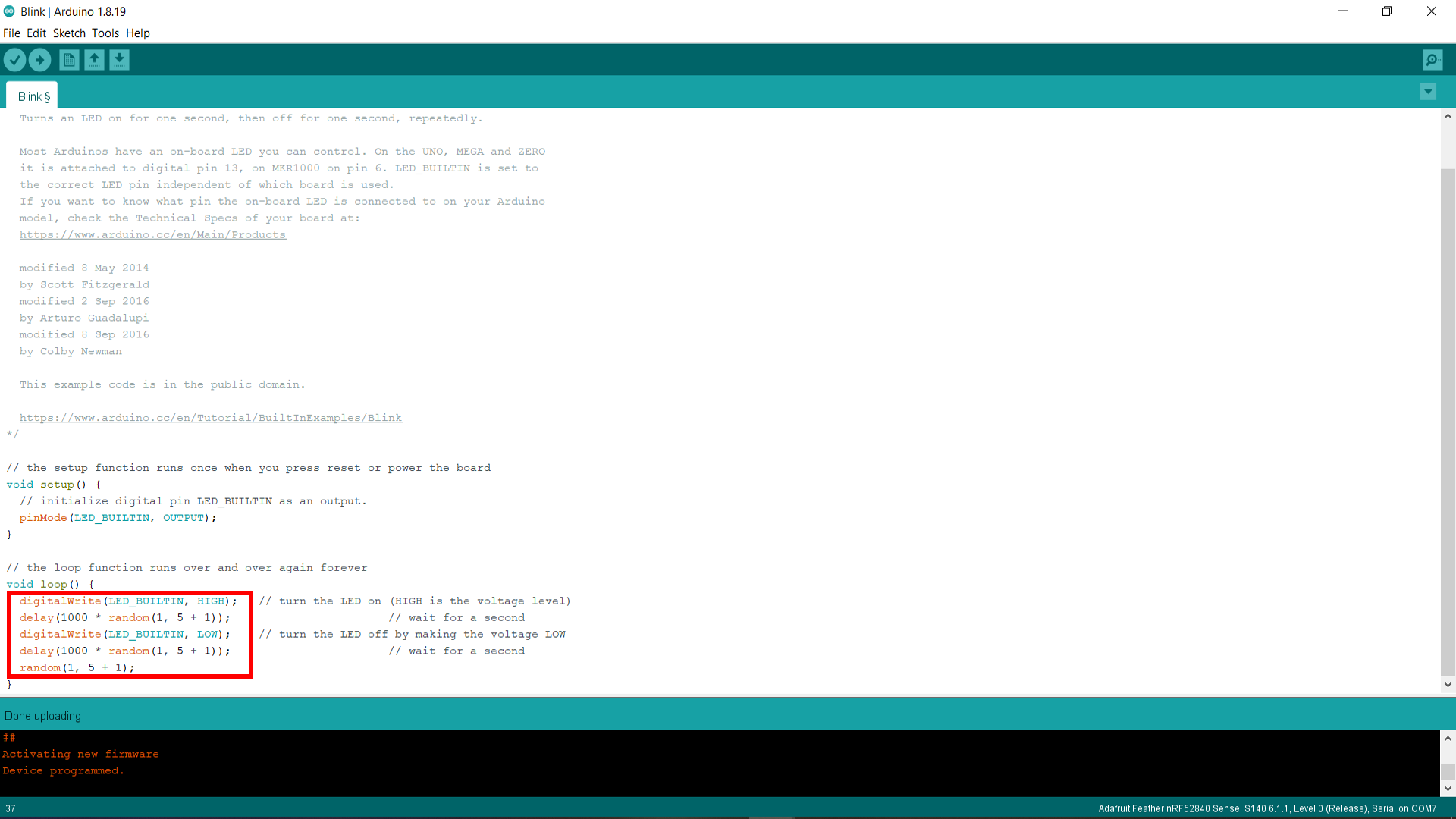
After adding the code, I went to make it in a text form, where the code can be seen, and selected the random(1,5) code, copied it, and then pasted that in blink.
After editing blink with it, I connected the port again, and uploaded the new information to the board. The LED started blinking in randomised patterns.
Video
Code for randomised values (1-5)
// the setup function runs once when you press reset or power the board
void setup() {
  // initialize digital pin LED_BUILTIN as an output.
  pinMode(LED_BUILTIN, OUTPUT);
}

// the loop function runs over and over again forever
void loop() {
  digitalWrite(LED_BUILTIN, HIGH);   // turn the LED on (HIGH is the voltage level)
  delay(1000 * random(1, 5 + 1));                       // wait for a second
  digitalWrite(LED_BUILTIN, LOW);    // turn the LED off by making the voltage LOW
  delay(1000 * random(1, 5 + 1));                       // wait for a second
  random(1, 5 + 1);
}