7. Input & Output device
This week I worked on defining my final project idea and started to getting used to the documentation process.
Group work
Yaqeen Fardan and I worked together.
What is input and output devices?
An input device sends information to a computer system for processing, and an output device reproduces or displays the results of that processing. Input devices only allow for input of data to a computer and output devices only receive the output of data from another device.
Group work
Task1: connect some sensors with microcontroller.
- Temperature and Humidity sensor “input device”.
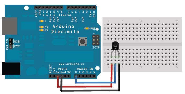
- How it is work? Temperature sensors work by providing readings via electrical signals. Sensors are composed of two metals that generate an electrical voltage or resistance when a temperature change occurs by measuring the voltage across the diode terminals. When the voltage increases, the temperature also increases.

-
reserch how can we connect the sensor to the MKR WiFi 1010.
-
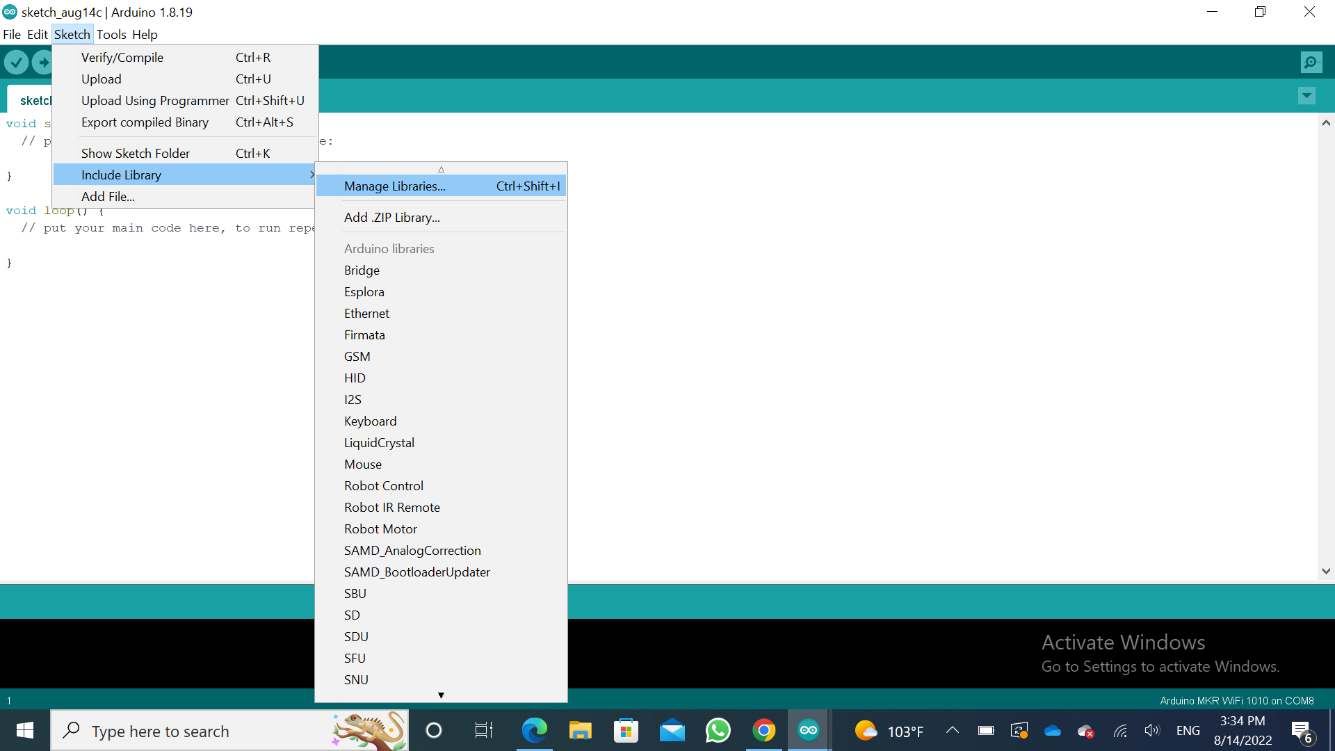
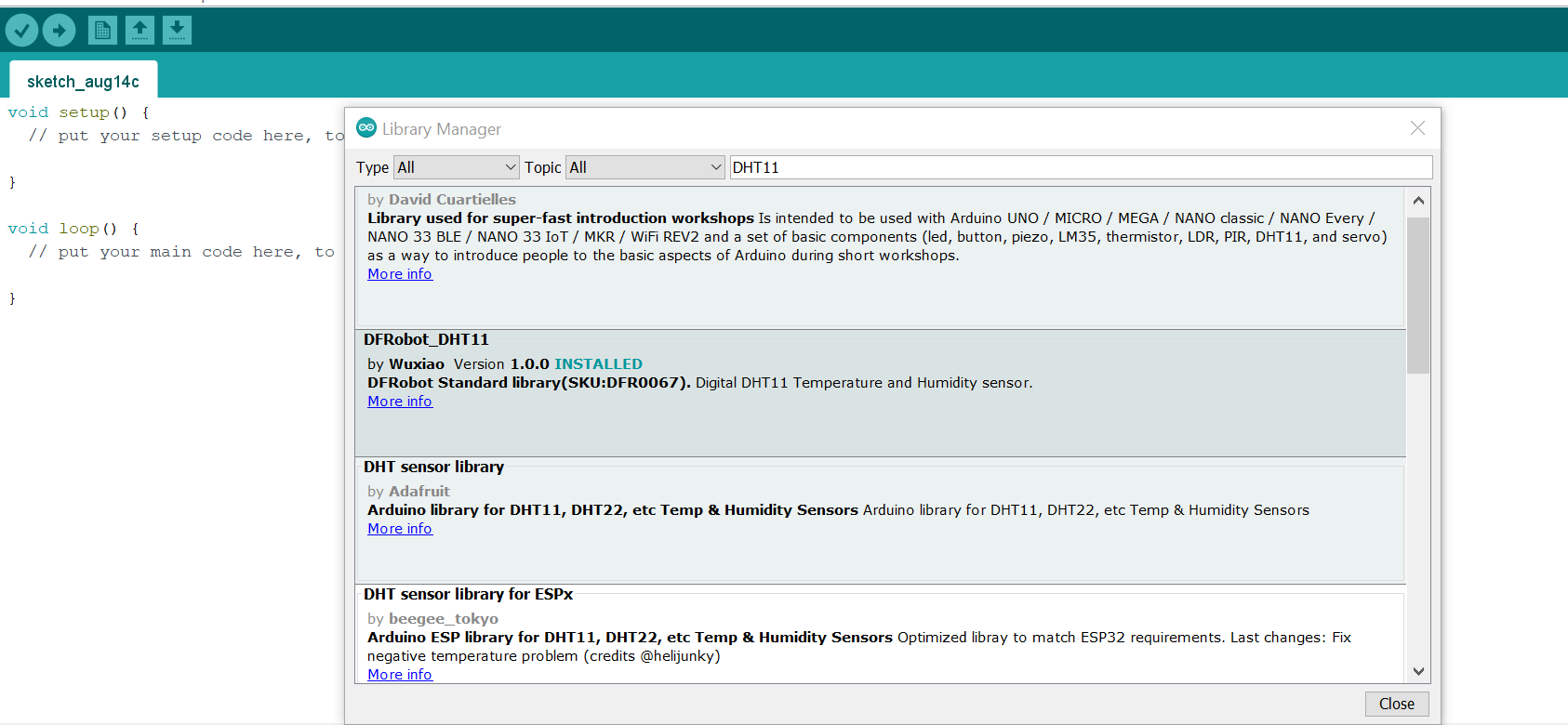
For each sensor, there is a liberary that is needed to be downloaded.
-
First we downloaded the liberary for it by the steps below:
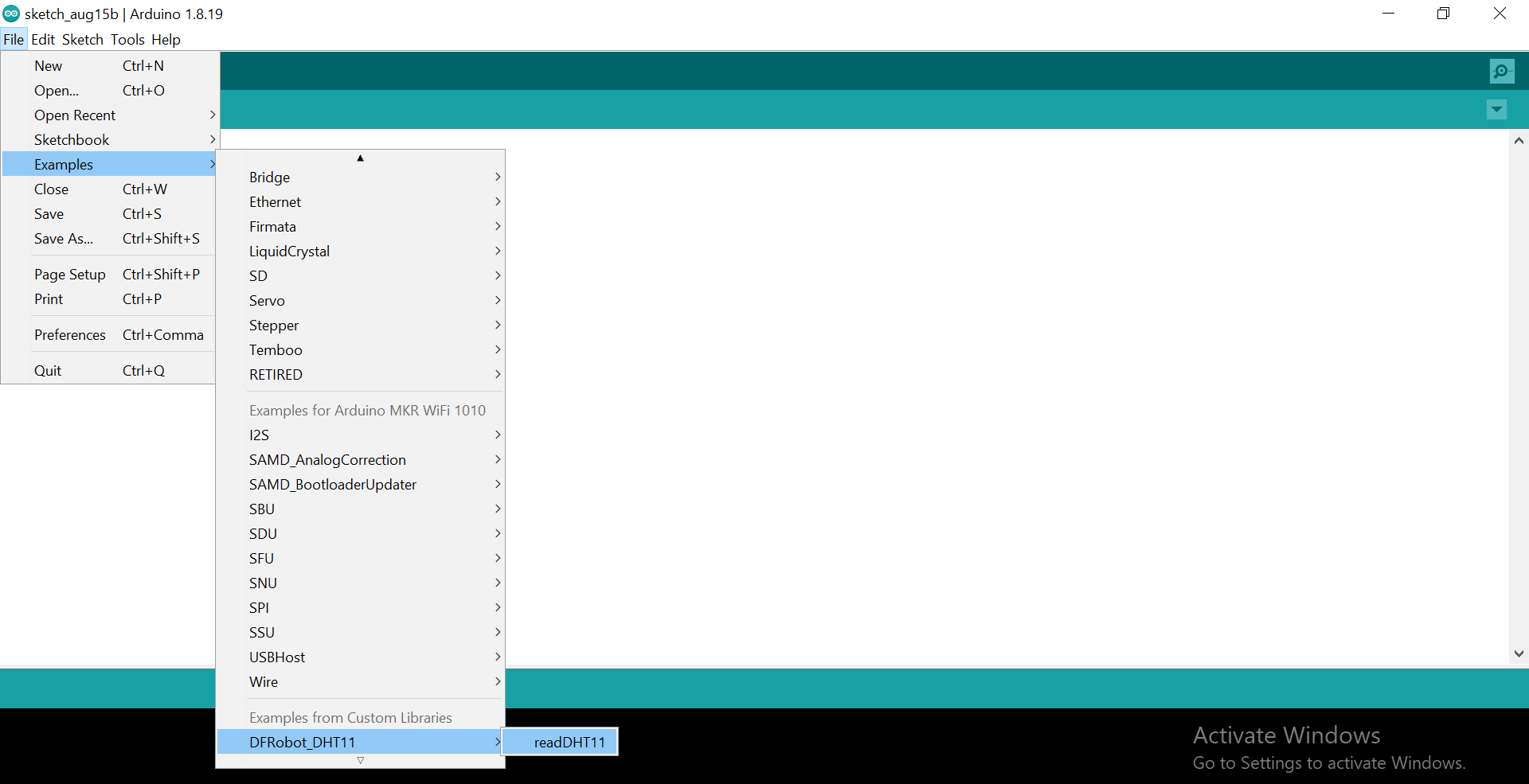
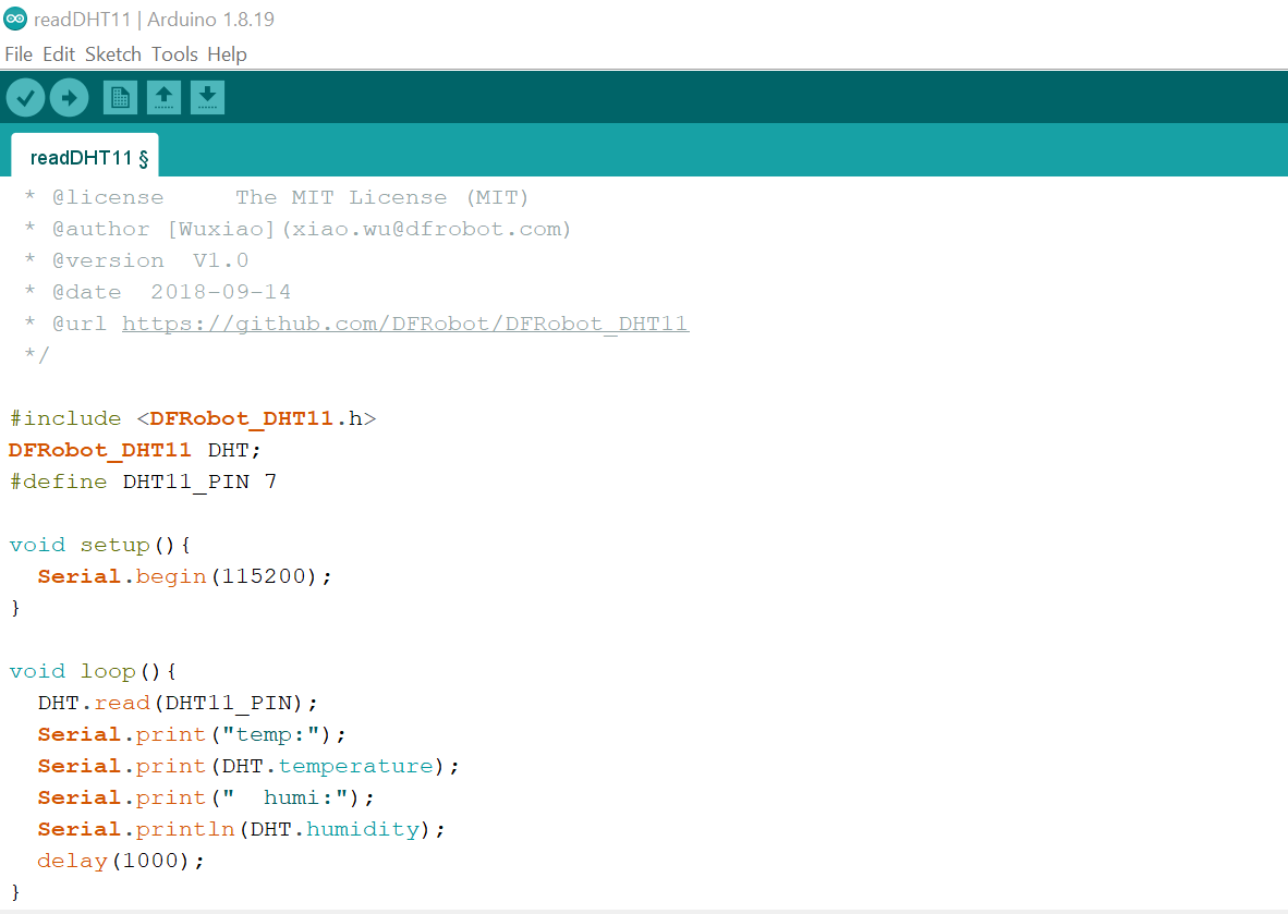
- Then we tried to use the code from arduino and different connection:
#include <DFRobot_DHT11.h>
DFRobot_DHT11 DHT;
#define DHT11_PIN 10

void setup(){
  Serial.begin(115200);
}

void loop(){
  DHT.read(DHT11_PIN);
  Serial.print("temp:");
  Serial.print(DHT.temperature);
  Serial.print("  humi:");
  Serial.println(DHT.humidity);
  delay(1000);
}

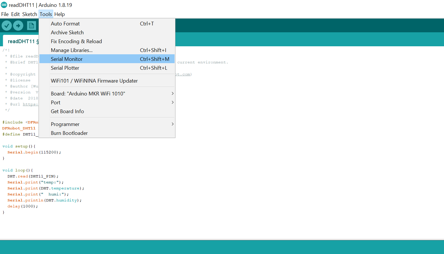
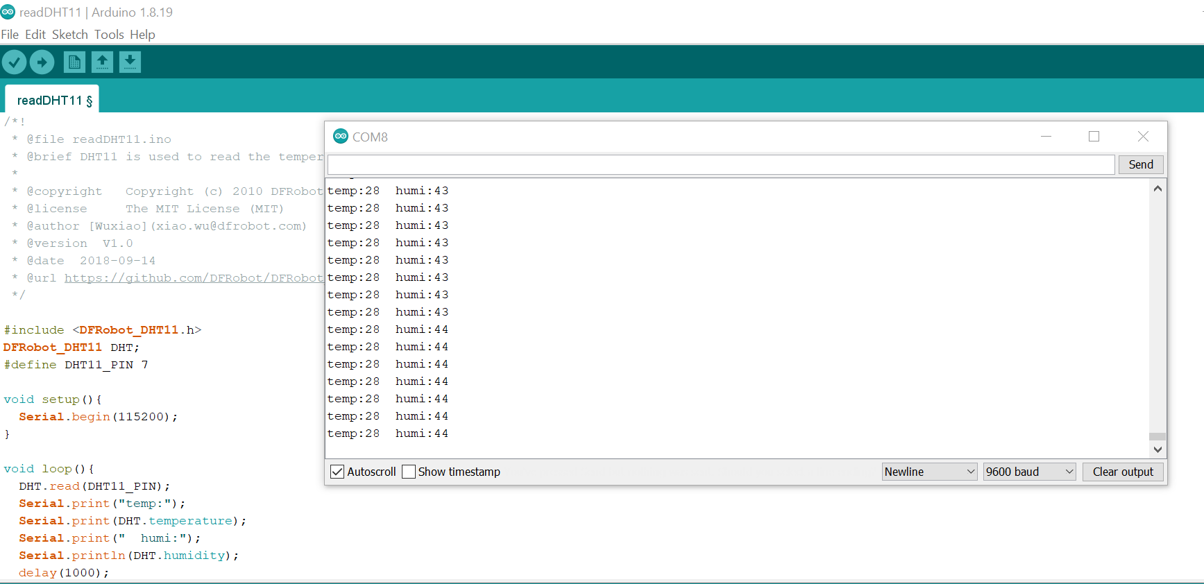
- Results: Tools –> Serial monitor
Task2: Servo motor.
- Output device
-
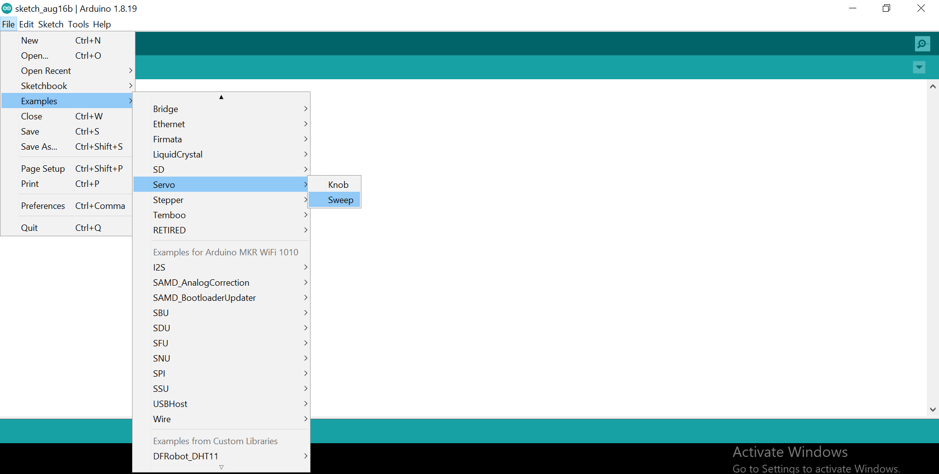
Research about “servo motor arduino code mkrwifi 1010” we found this website
-
How does a servo motor work? A servo motor is an electromechanical device that produces torque and velocity based on the supplied current and voltage. A servo motor works as part of a closed loop system providing torque and velocity as commanded from a servo controller utilizing a feedback device to close the loop.
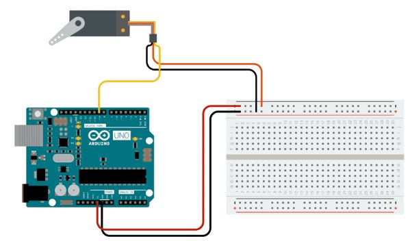
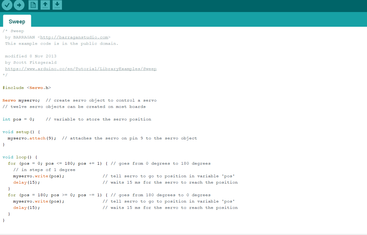
- we tried to connected the servo motor with the sensor by the code below:
*/

#include <Servo.h>
#include <DFRobot_DHT11.h>
DFRobot_DHT11 DHT;
#define DHT11_PIN 7

void sep(){
  Serial.begin(115200);
}


Servo myservo;  // create servo object to control a servo
// twelve servo objects can be created on most boards

int pos = 0;    // variable to store the servo position

void setup() {
  myservo.attach(9);  // attaches the servo on pin 9 to the servo object
}

void loop() {
  for (pos = 0; pos <= 180; pos += 1) { // goes from 0 degrees to 180 degrees
    // in steps of 1 degree
    myservo.write(pos);              // tell servo to go to position in variable 'pos'
    delay(15);                       // waits 15 ms for the servo to reach the position
  }
  for (pos = 180; pos >= 0; pos -= 1) { // goes from 180 degrees to 0 degrees
    myservo.write(pos);              // tell servo to go to position in variable 'pos'
    delay(15);                       // waits 15 ms for the servo to reach the position
  }
    DHT.read(DHT11_PIN);
  Serial.print("temp:");
  Serial.print(DHT.temperature);
  Serial.print("  humi:");
  Serial.println(DHT.humidity);
  delay(1000);

}

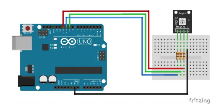
Task3: RGB LED
- An RGB LED is a combination of three LEDs in just one package: red, green and blue; there are two kinds of RGB LEDs: common cathode and common anode RGB LEDs; you generate different colors by adjusting the brightness of each of the three LEDs of the RGB LED; to adjust the brightness of each LED, you use a PWM signal.
int red_light_pin= 4;
int green_light_pin = 5;
int blue_light_pin = 3;
void setup() {
  pinMode(red_light_pin, OUTPUT);
  pinMode(green_light_pin, OUTPUT);
  pinMode(blue_light_pin, OUTPUT);
}
void loop() {
  RGB_color(255, 0, 0); // Red
  delay(500);
  RGB_color(0, 255, 0); // Green
  delay(500);
  RGB_color(0, 0, 255); // Blue
  delay(500);
  RGB_color(255, 255, 125); // Raspberry
  delay(500);
  RGB_color(0, 255, 255); // Cyan
  delay(500);
  RGB_color(255, 0, 255); // Magenta
  delay(500);
  RGB_color(255, 255, 0); // Yellow
  delay(500);
  RGB_color(255, 255, 255); // White
  delay(500);
}
void RGB_color(int red_light_value, int green_light_value, int blue_light_value)
 {
  analogWrite(red_light_pin, red_light_value);
  analogWrite(green_light_pin, green_light_value);
  analogWrite(blue_light_pin, blue_light_value);
}
Task 4: Servo motor with Temperature sensor.
/*!
 * @file readDHT11.ino
 * @brief DHT11 is used to read the temperature and humidity of the current environment.
 *
 * @copyright   Copyright (c) 2010 DFRobot Co.Ltd (http://www.dfrobot.com)
 * @license     The MIT License (MIT)
 * @author [Wuxiao](xiao.wu@dfrobot.com)
 * @version  V1.0
 * @date  2018-09-14
 * @url https://github.com/DFRobot/DFRobot_DHT11
 */

#include <DFRobot_DHT11.h>
DFRobot_DHT11 DHT;
#define DHT11_PIN 10
#include <Servo.h>
int temp;

Servo myservo;  // create servo object to control a servo
// twelve servo objects can be created on most boards

int pos = 0;    // variable to store the servo position
void setup(){
  Serial.begin(115200);
   myservo.attach(4);  // attaches the servo on pin 9 to the servo object
}

void loop(){
  DHT.read(DHT11_PIN);
  Serial.println(DHT.temperature);
  delay(1000);
  if (DHT.temperature > 15 && DHT.temperature <30){
      for (pos = 0; pos <= 180; pos += 1) { // goes from 0 degrees to 180 degrees
    // in steps of 1 degree
      myservo.write(pos);              // tell servo to go to position in variable 'pos'
      delay(15);                       // waits 15 ms for the servo to reach the position
      }
      for (pos = 180; pos >= 0; pos -= 1) { // goes from 180 degrees to 0 degrees
      myservo.write(pos);              // tell servo to go to position in variable 'pos'
      delay(15);                       // waits 15 ms for the servo to reach the position
      }
  }
}
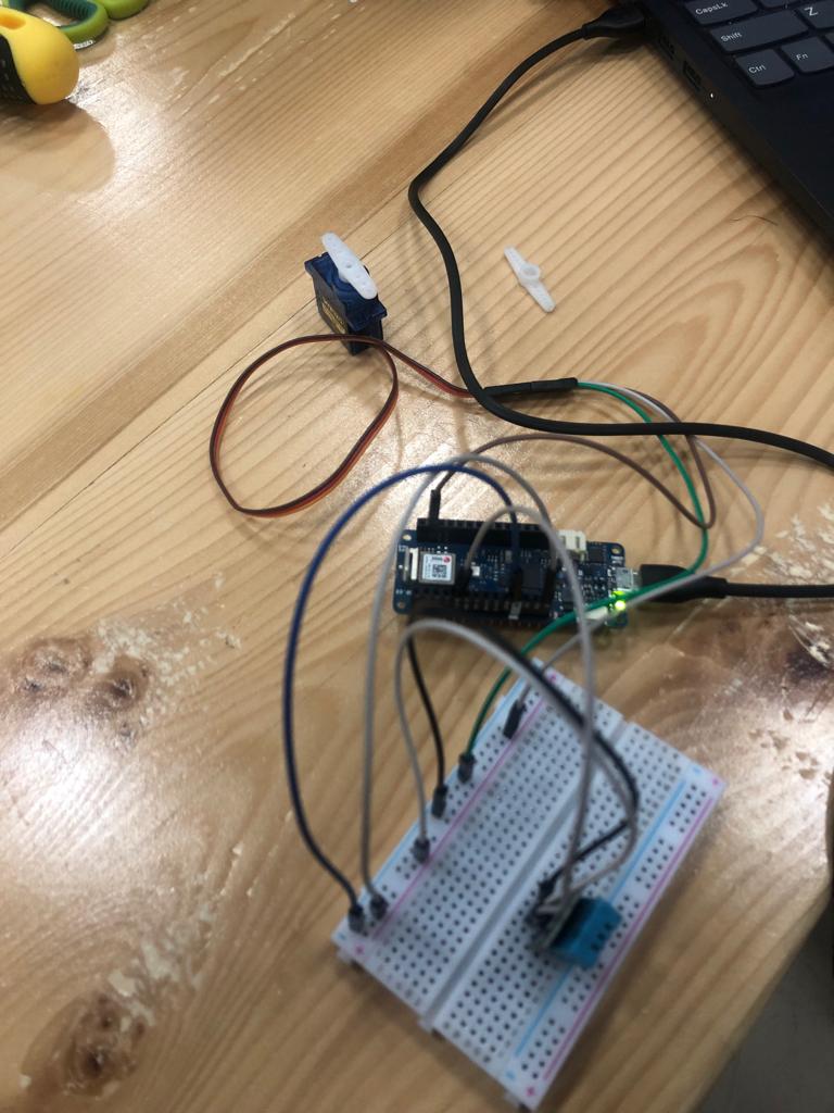
- when Temp < 30 the motor will start to move.