3. Computer controlled cutting
This week I worked on defining my final project idea and started to getting used to the documentation process.
Vinyl
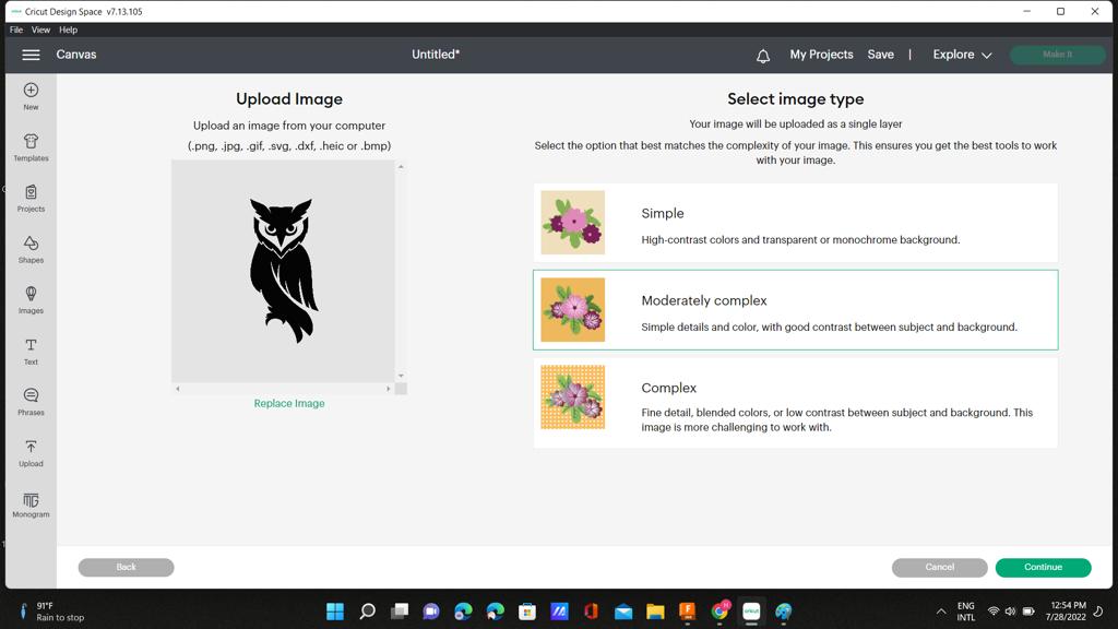
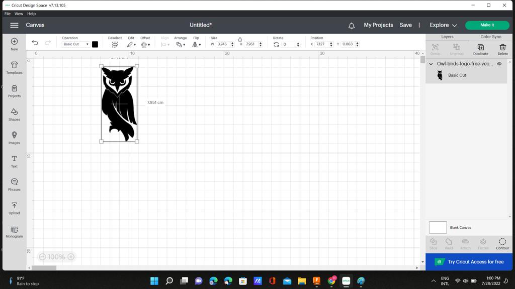
At first I had to choose a logo to cut, so I searched on google for an owl logo and found a nice logo, after that I used circut design space and uploaded my image there. choosing the moderately complex option as shown.
I removed the background
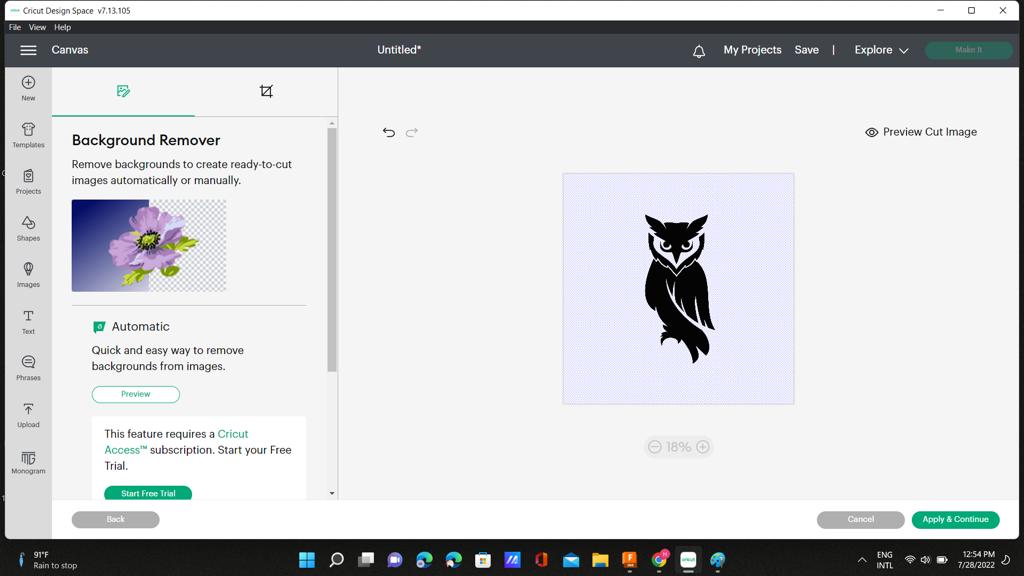
I scaled it down for it to be a bit smaller.
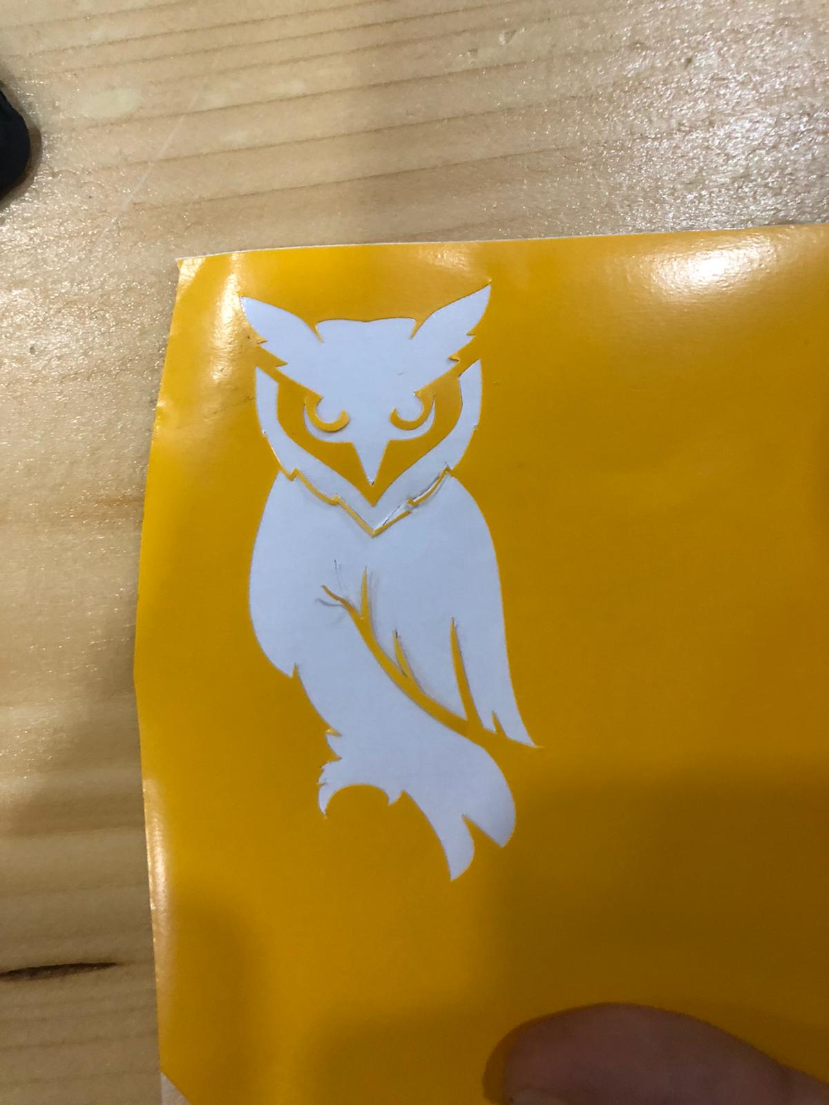
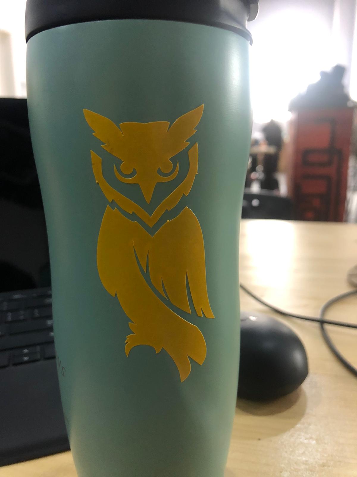
After cutting using the vinyl cutter
Laser cutting
PressFit
Individual Assignment:
Doing a parametric design pressfit out of cardboard.
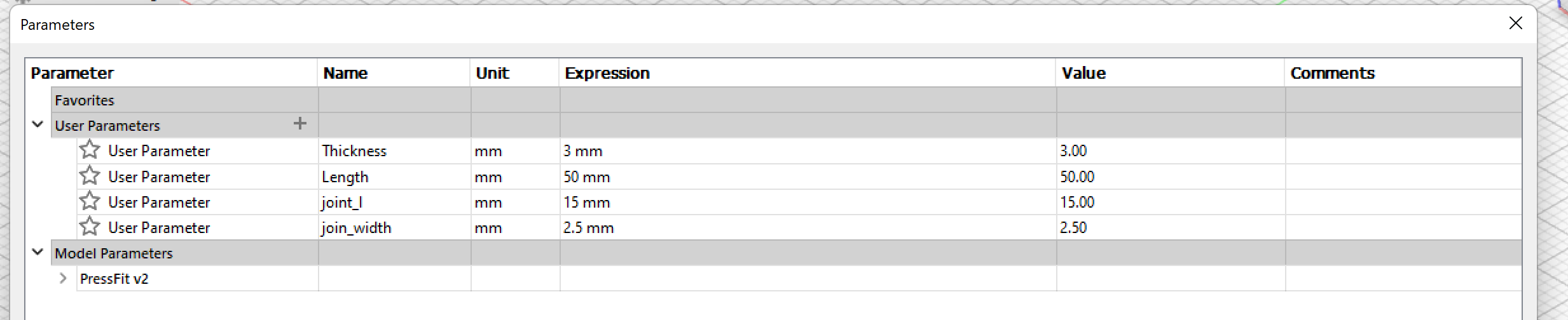
From what we concluded from the group work, cutting speed would be 40 mm/s, power would be 35%, and joint width would be 2.5mm.
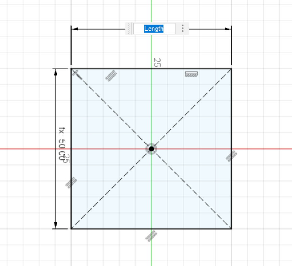
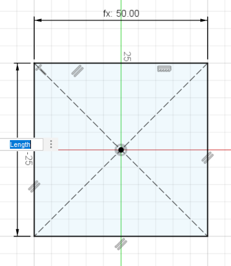
Step 1: Creating the parameters for the pressfit.
Step 2: Making the base of the design
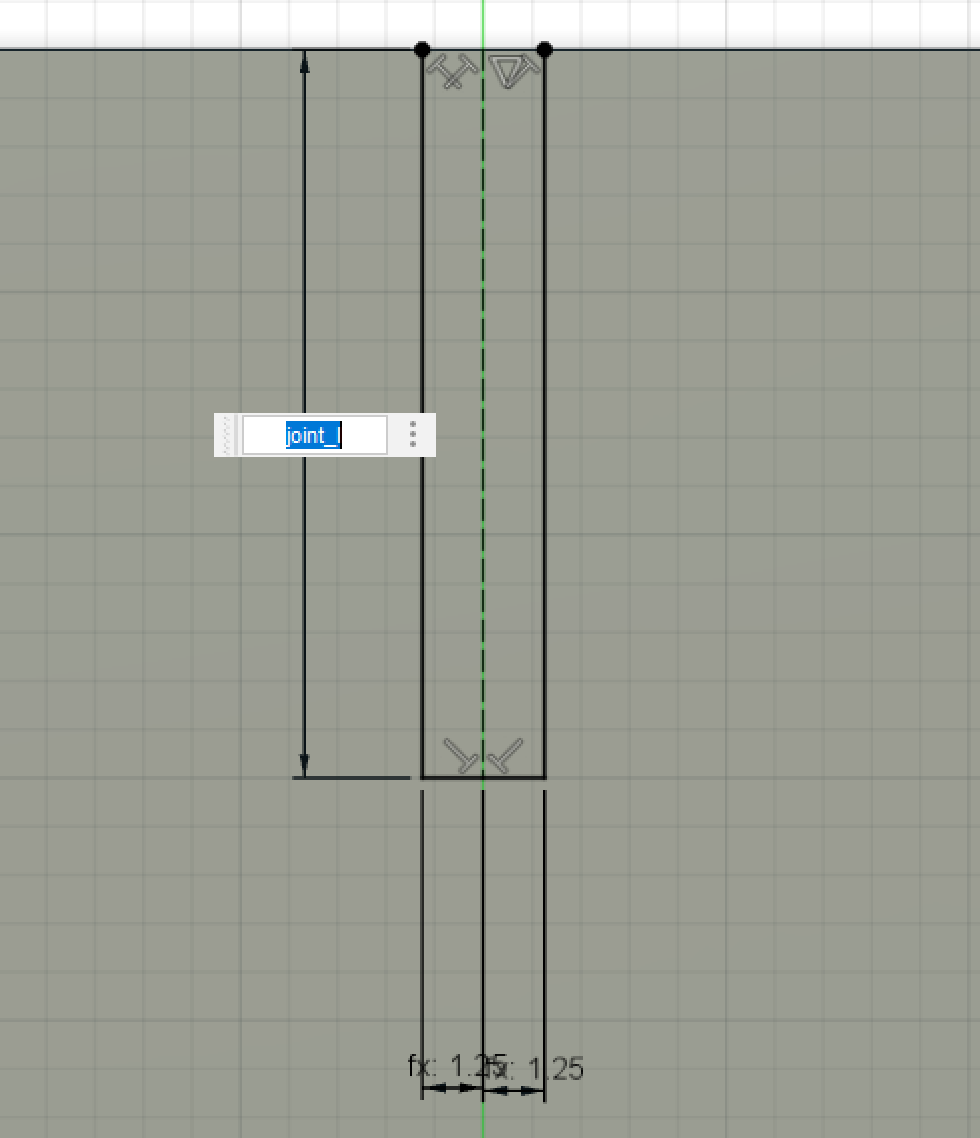
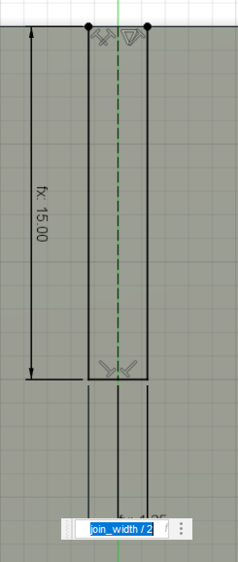
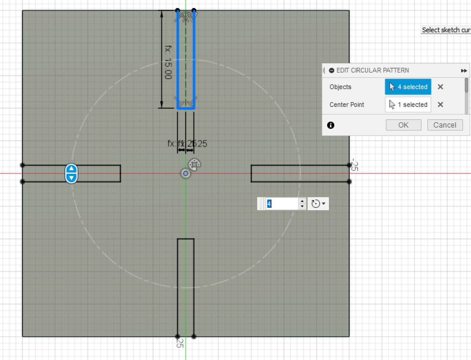
Step 3: Sketching the joint gaps
Making it on four sides using circular pattern
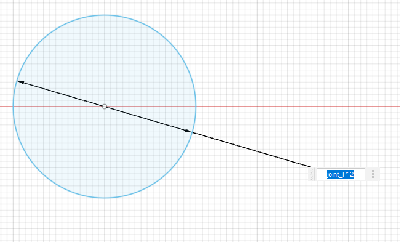
Step 4: For my design I’m planning to do a 90 degree angle joint so I made a circle to add all of the faces into a cube, and joint length would be the radious of the circle.
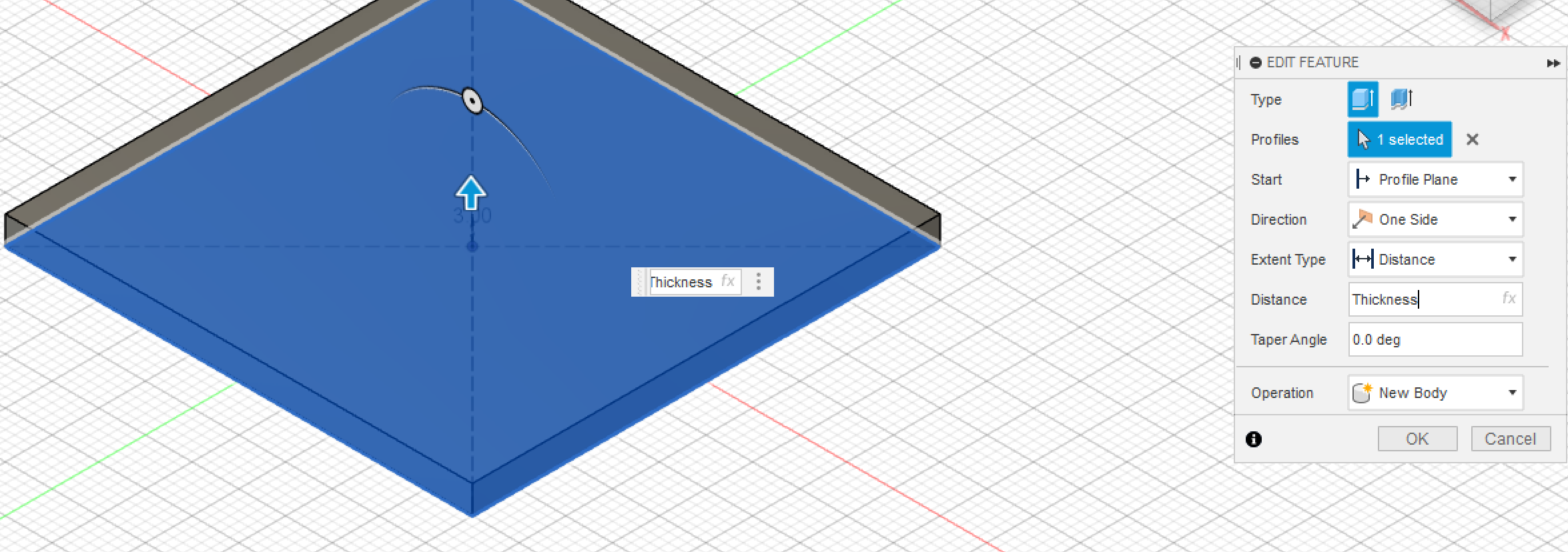
Step 5: Extruding all of the design with the parameters.
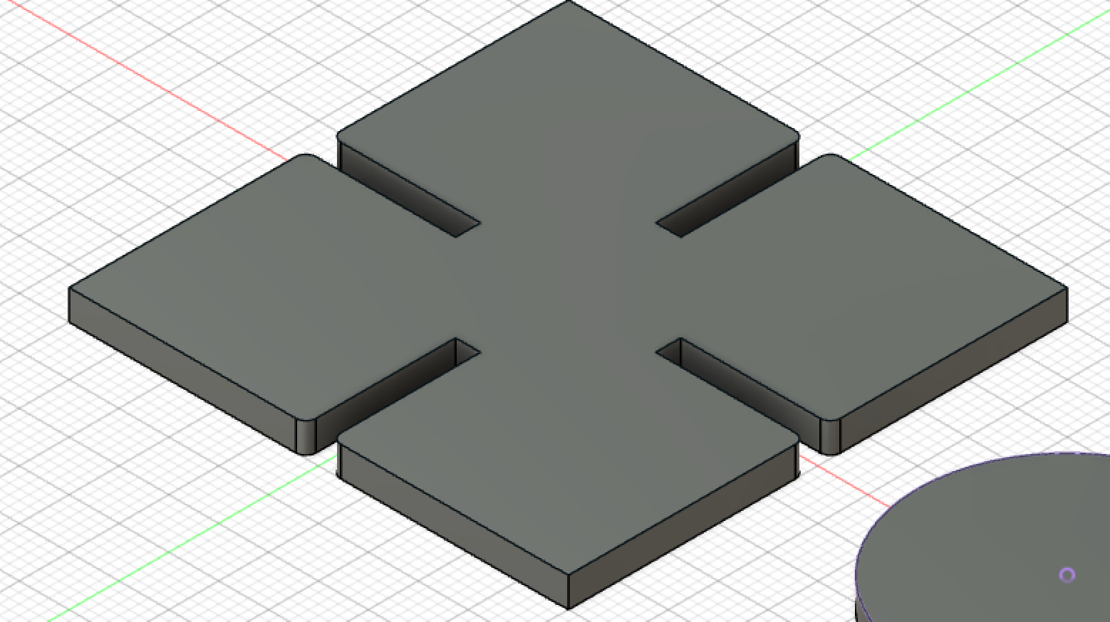
Step 5.5: Results
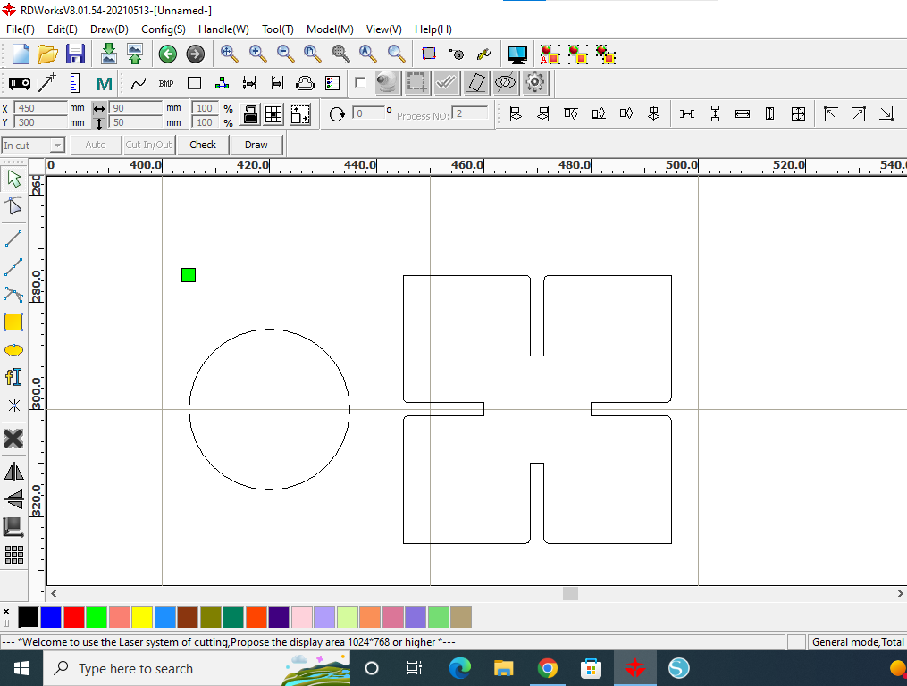
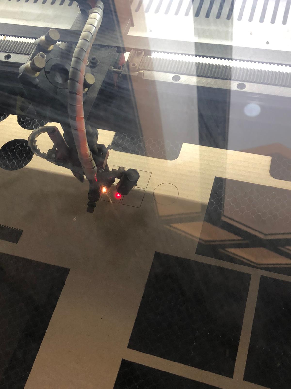
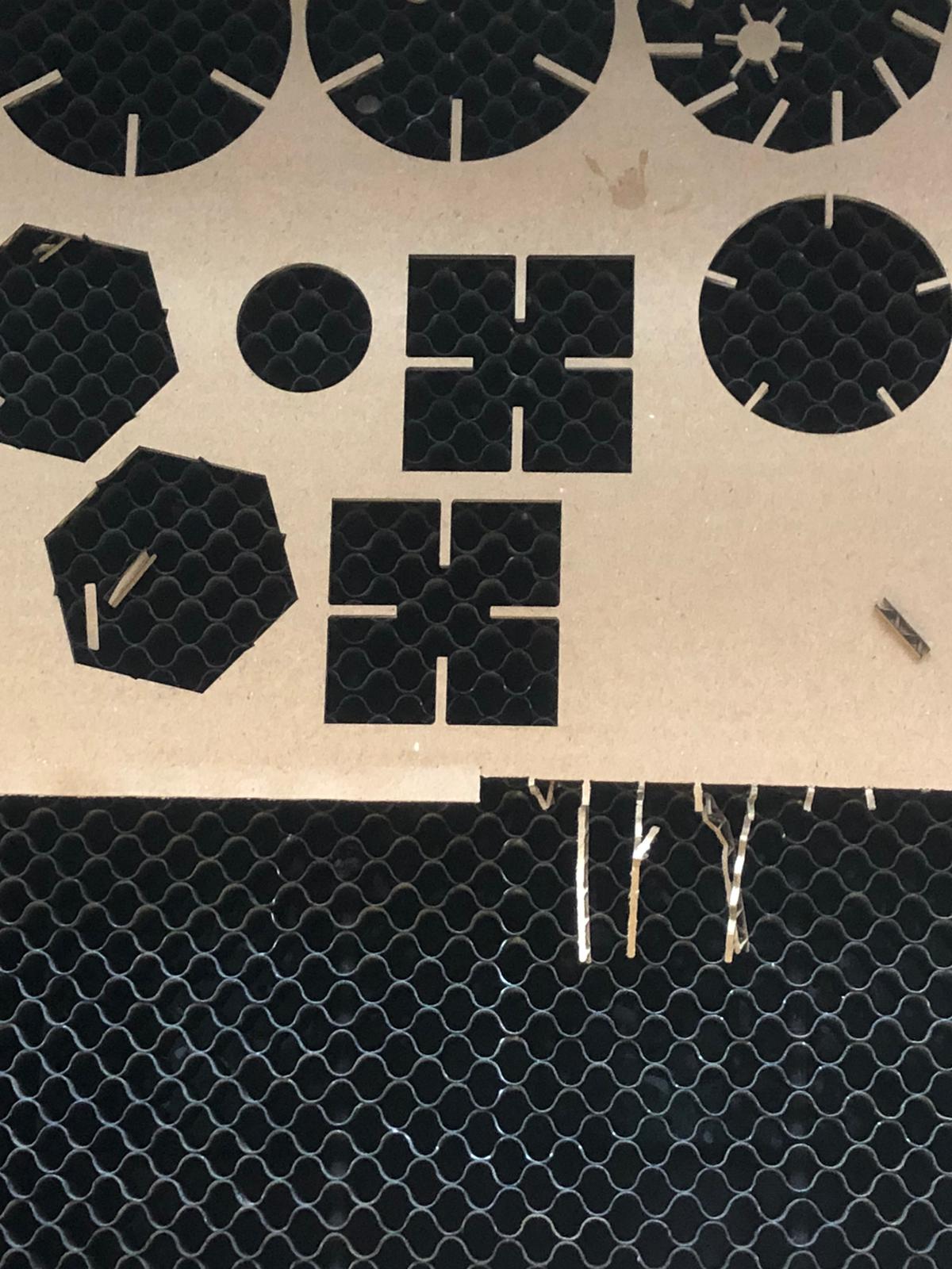
Step 6: Cutting the pieces. To cut the pressfit I had to upload it to RDworks that which is what the laser cutter use as a program
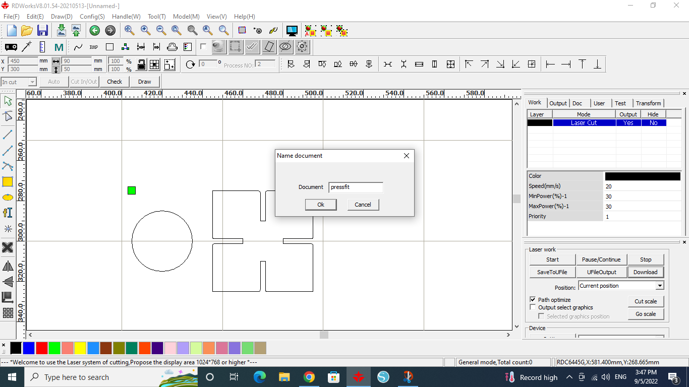
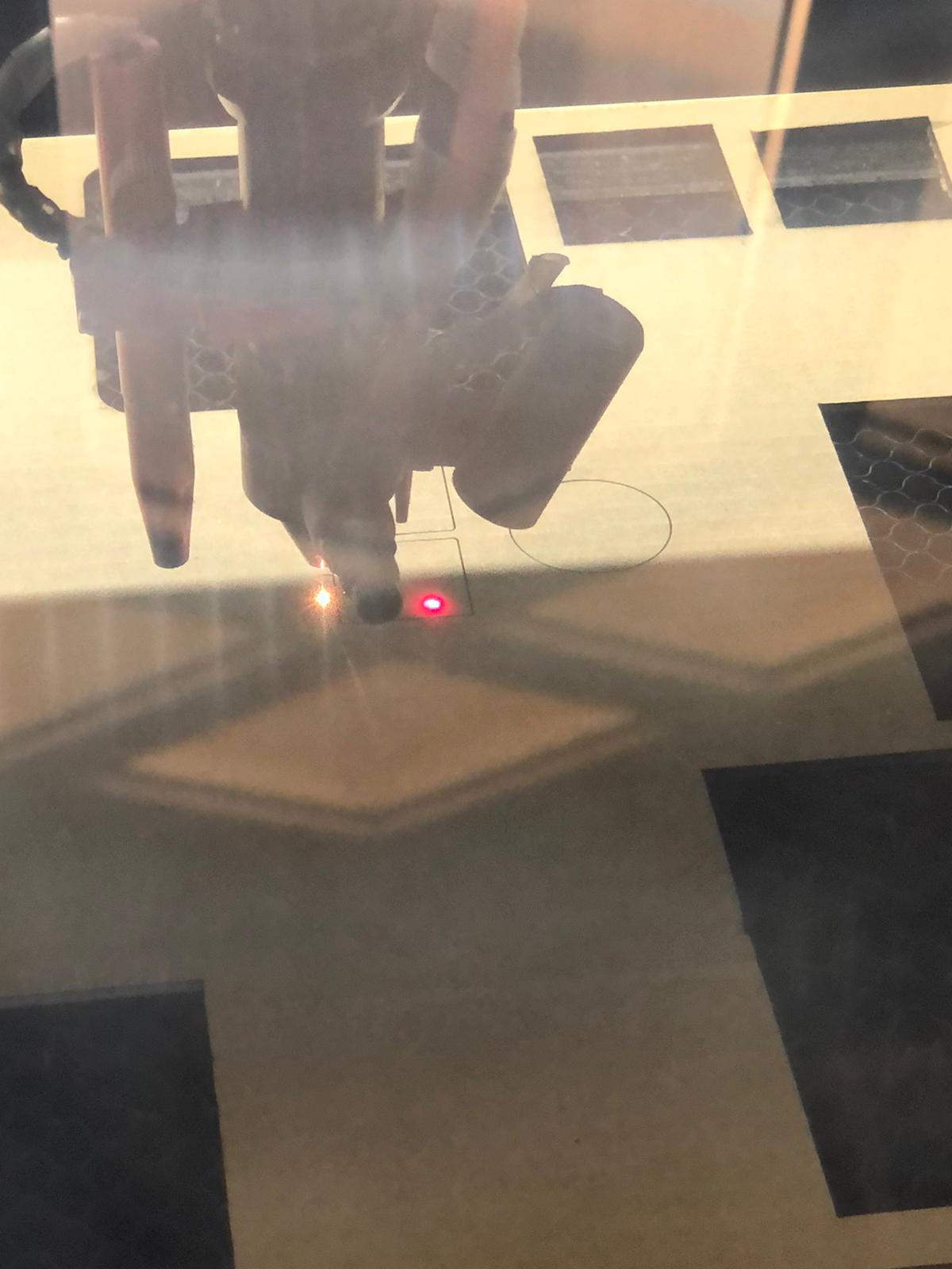
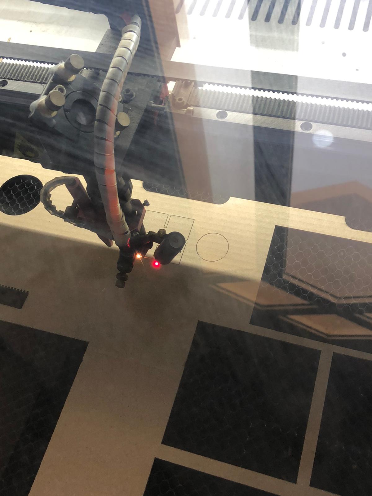
As you can see below the laser cutter is starting to cut the pieces and the parameters for it (laser power, cutting speed, etc…) are the same as it mentioned in the group assignment. and it is shown in the screenshots above.
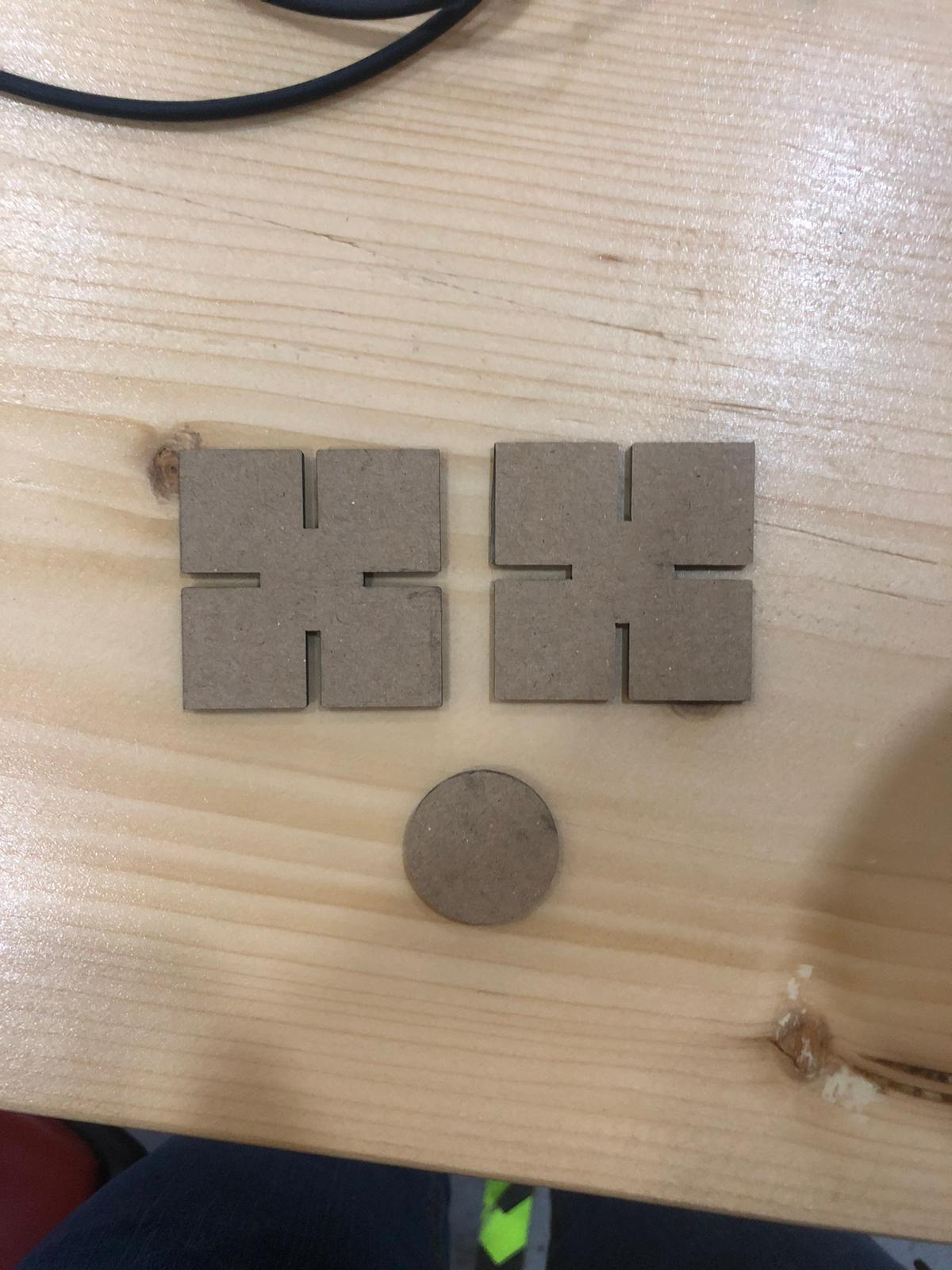
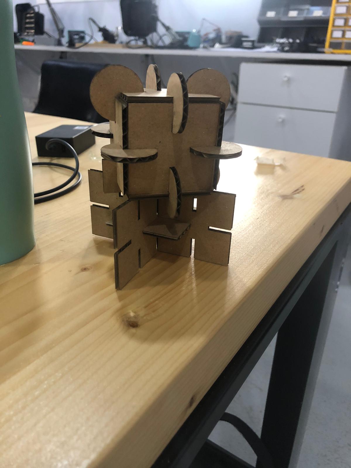
Step 7: Testing the joint system.
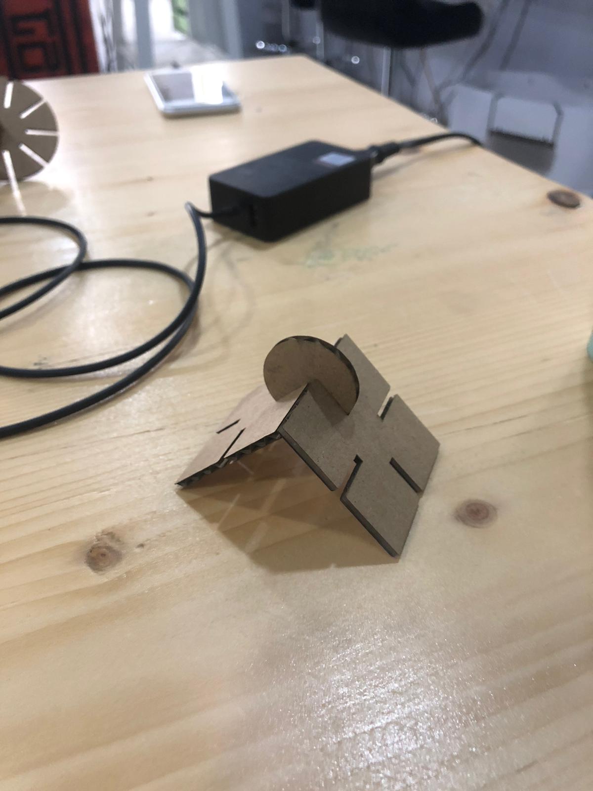
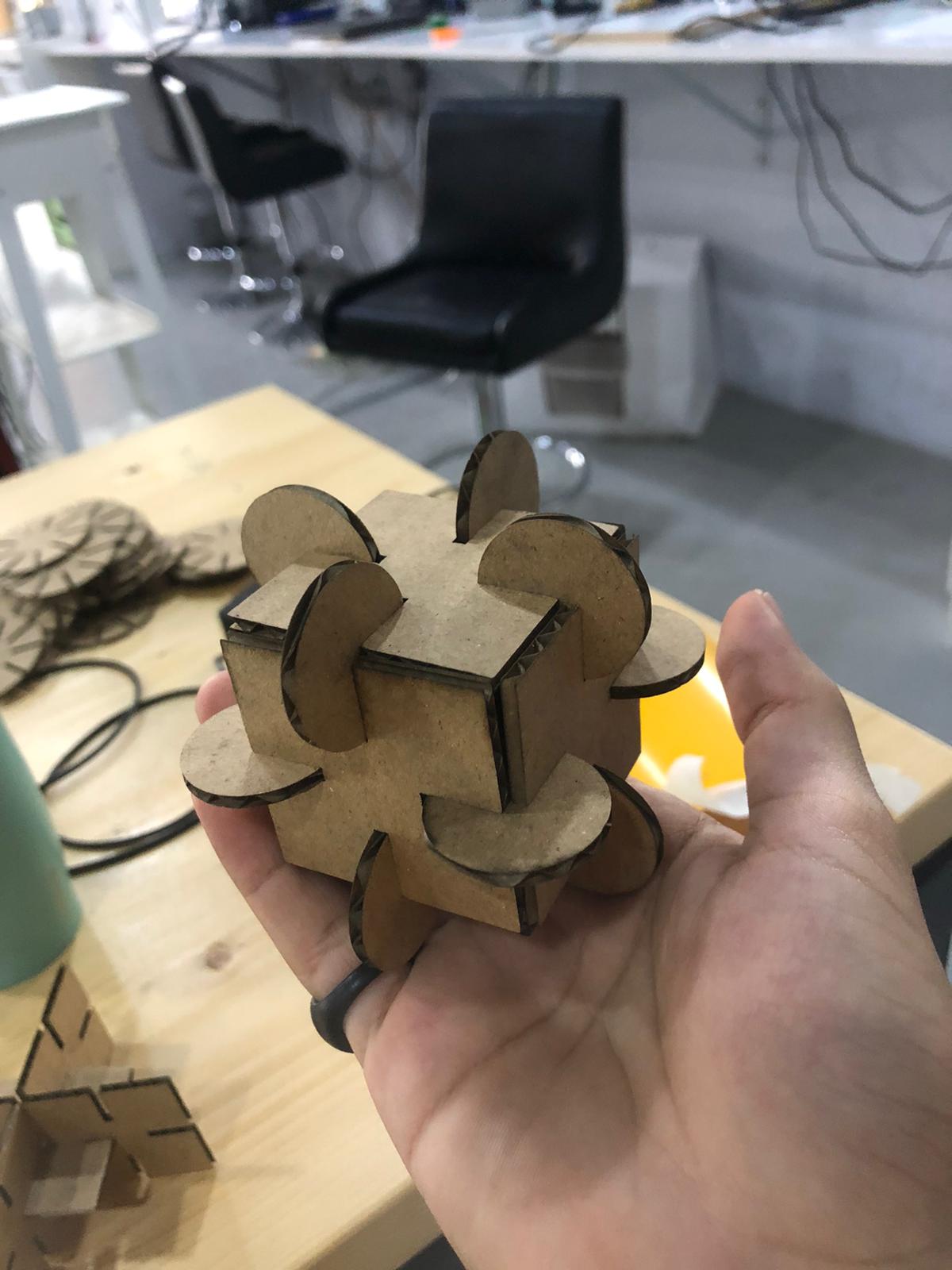
Once it is satisfactory we move to Step 8: Final Assembly