7. Input & Output device
Input and output devices are connected to each other through a current connection (electrical charges) when dealing with electronics. DC and AC are two types of currents. DC is a direct current travelling in one direction only most commonly found in batteries. While, AC refers to alternating current which can be found in the switch boards, electrical sockets etc.
There are a lot of examples of input and devices around us, e.g. keyboards and computer screen, electrical switch and its connection with a bulb/fan. There are two types of inputs, Digital and Analogue. Digital inputs provide you with binary signal only i.e. on/off, high/low, voltage/ground. And analogue inputs are variable, its signal transmission can be controlled. You can increase or decrease your input. One example of analogue input is a fan speed controller switch. A sensor is a good example for an output device, e.g. Temperature sensor measures the temperature, Ultrasonic sensor measures the distance to an object with the help of high frequency sound waves.
Individual Assignment
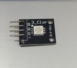
My first task is to test the output of a sensor. I took SMD RGB sensor which has an LED mounted on the surface. It has four male pins representing 3 colour pins (blue, red & green) and a GND (negative/Vin/VCC).
My second task was to program a capacitive sensor, which senses if any charges are detected (touch being the input in this case). I used MPR121 which has 12 capacitive touch sensors. I followed some guidelines from an online tutorial to setup the sensor with the microcontroller.
Output Testing
Took four male-to-male pins and attached their one side to the SMD RGB LED output sensor and other to the microcontroller (Adafruit feather nrf52840 express). The negative on the sensor must be connected to the ground and rest of three color pins can be connected to any input/output pins on the microcontroller. Its wiring is shown below.
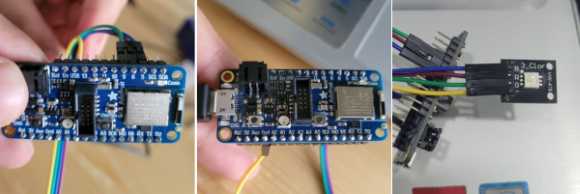
After connecting the wires, added a code in arduino ide to display 3 different colors and connected the controller to the arduino ide. After uploading the code, following output was seen.
Code for blinking 3 different coloured light:
// the setup function runs once when you press reset or power the board

void setup() {
  // initialize digital pin LED_BUILTIN as an output.
  pinMode(5, OUTPUT);
  pinMode(6, OUTPUT);
  pinMode(9, OUTPUT);
}

// the loop function runs over and over again forever
void loop() {
  digitalWrite(5, HIGH);   // Blue LED at pin 5
  delay(1000);
  digitalWrite(5, LOW);
  delay(1000);

  digitalWrite(6, HIGH);   // Red LED at pin 6
  delay(1000);
  digitalWrite(6, LOW);
  delay(1000);

  digitalWrite(9, HIGH);   // Green LED at pin 9
  delay(1000);
  digitalWrite(9, LOW);
  delay(1000);
}
Input Testing
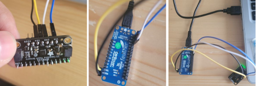
For an input test, I took MPR121 and connected it with my adafruit microcontroller as shown in the image below.
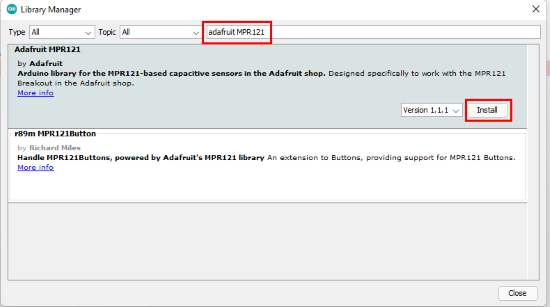
But before programming the microcontroller I have to install the MPR121 library to the arduino ide. Therefore I searched for the mpr121 library in the library manager (GO TO: sketch>include_library>manage_libraries) and tried installing it.
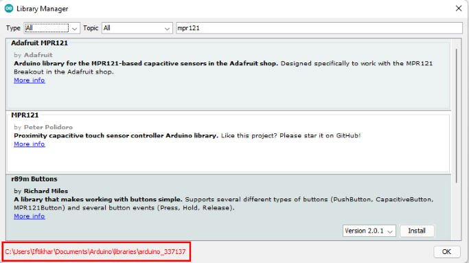
For some unknown reasons I was unable to install the library, it showed me a message stating the link of the library folder. I used a hack with my colleague Hussain’s help. Since he was able to install it on his computer, so I took the library files from him and copy pasted them in the same folder which was shown at the bottom of the library manager. And it worked.
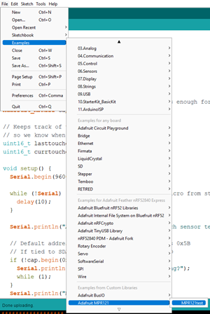
Next, I opened an example from mpr library to test the sensor I had connected.
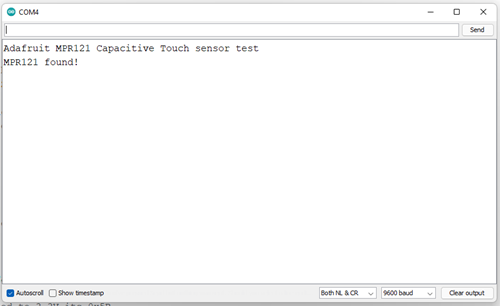
I uploaded the code to the microcontroller and opened the serial plotter window to see if the program is working. As a result, device found message was displayed on the plotter screen which means program is running successfully.
Now I tried to test the 12 sensor pins if they are working. Since the program code is supposed to display ‘touched’ pin number whenever a pin senses a touch and ‘released’ pin number when the touch is released. The display of this program can be seen from the video below.
The code which I used for the test is given below:
#include <SPI.h>
#include <Wire.h>
#include "Adafruit_MPR121.h"
#ifndef _BV
#define _BV(bit) (1 << (bit))
#endif

// You can have up to 4 on one i2c bus but one is enough for testing!
Adafruit_MPR121 cap = Adafruit_MPR121();

// Keeps track of the last pins touched
// so we know when buttons are 'released'
uint16_t lasttouched = 0;
uint16_t currtouched = 0;

void setup() {

  Serial.begin(9600);

  while (!Serial) { // needed to keep leonardo/micro from starting too fast!
    delay(10);
  }

  Serial.println("Adafruit MPR121 Capacitive Touch sensor test");

  // Default address is 0x5A, if tied to 3.3V its 0x5B
  // If tied to SDA its 0x5C and if SCL then 0x5D
  if (!cap.begin(0x5A)) {
    Serial.println("MPR121 not found, check wiring?");
    while (1);
  }
  Serial.println("MPR121 found!");
}

void loop() {
  // Get the currently touched pads
  currtouched = cap.touched();

  for (uint8_t i=0; i<12; i++) {
    // it if *is* touched and *wasnt* touched before, alert!
    if ((currtouched & _BV(i)) && !(lasttouched & _BV(i)) ) {
      Serial.print(i); Serial.println(" touched");

    }
    // if it *was* touched and now *isnt*, alert!
    if (!(currtouched & _BV(i)) && (lasttouched & _BV(i)) ) {
      Serial.print(i); Serial.println(" released");

    }
  }

  // reset our state
  lasttouched = currtouched;

  // comment out this line for detailed data from the sensor!
  return;

  // debugging info, what
  Serial.print("\t\t\t\t\t\t\t\t\t\t\t\t\t 0x"); Serial.println(cap.touched(), HEX);
  Serial.print("Filt: ");
  for (uint8_t i=0; i<12; i++) {
    Serial.print(cap.filteredData(i)); Serial.print("\t");
  }
  Serial.println();
  Serial.print("Base: ");
  for (uint8_t i=0; i<12; i++) {
    Serial.print(cap.baselineData(i)); Serial.print("\t");
  }
  Serial.println();

  // put a delay so it isn't overwhelming
  delay(100);
}
Input & Output Testing
I linked my input device (mpr121) with the output device (SMD RGB LED) which were programmed above. So whenever I touch any of the sensor pins (input), the RGB sensor should display a green light or else keeps it red. I manipulated the above code a little and it worked. Following video shows the working of both the sensors as expected.
Following code was used for this activity:
#include <SPI.h>
#include <Wire.h>
#include "Adafruit_MPR121.h"
int red = 9;
int blue = 10;
int green = 6;
#ifndef _BV
#define _BV(bit) (1 << (bit))
#endif

// You can have up to 4 on one i2c bus but one is enough for testing!
Adafruit_MPR121 cap = Adafruit_MPR121();

// Keeps track of the last pins touched
// so we know when buttons are 'released'
uint16_t lasttouched = 0;
uint16_t currtouched = 0;

void setup() {
  pinMode(red, OUTPUT);
  pinMode(blue, OUTPUT);
  pinMode(green, OUTPUT);
  Serial.begin(9600);

  while (!Serial) { // needed to keep leonardo/micro from starting too fast!
    delay(10);
  }

  Serial.println("Adafruit MPR121 Capacitive Touch sensor test");

  // Default address is 0x5A, if tied to 3.3V its 0x5B
  // If tied to SDA its 0x5C and if SCL then 0x5D
  if (!cap.begin(0x5A)) {
    Serial.println("MPR121 not found, check wiring?");
    while (1);
  }
  Serial.println("MPR121 found!");
}

void loop() {
  // Get the currently touched pads
  currtouched = cap.touched();

  for (uint8_t i=0; i<12; i++) {
    // it if *is* touched and *wasnt* touched before, alert!
    if ((currtouched & _BV(i)) && !(lasttouched & _BV(i)) ) {
      Serial.print(i); Serial.println(" touched");
      digitalWrite(6, HIGH);
      digitalWrite(9, LOW);
      digitalWrite(10, LOW);
      delay(10);
    }
    // if it *was* touched and now *isnt*, alert!
    if (!(currtouched & _BV(i)) && (lasttouched & _BV(i)) ) {
      Serial.print(i); Serial.println(" released");
      digitalWrite(9, HIGH);
      digitalWrite(6, LOW);
      digitalWrite(10, LOW);
      delay(10);
    }
  }

  // reset our state
  lasttouched = currtouched;

  // comment out this line for detailed data from the sensor!
  return;

  // debugging info, what
  Serial.print("\t\t\t\t\t\t\t\t\t\t\t\t\t 0x"); Serial.println(cap.touched(), HEX);
  Serial.print("Filt: ");
  for (uint8_t i=0; i<12; i++) {
    Serial.print(cap.filteredData(i)); Serial.print("\t");
  }
  Serial.println();
  Serial.print("Base: ");
  for (uint8_t i=0; i<12; i++) {
    Serial.print(cap.baselineData(i)); Serial.print("\t");
  }
  Serial.println();

  // put a delay so it isn't overwhelming
  delay(100);
}