7. Input & Output device
The embedded programming week was to introduce us to multiple programming softwares so that we have the freedom to choose the one that we will use for this week. Whether it’s TInkerCAD, Arduino IDE and Python. Personally I’ll be using Arduino IDE.
An input device reads information from the surrounding and sends it to the microcontroller while an output device uses information from the microcontroller and shares this information to us, the audience and literal controllers of the microcontroller.
To summarize:
Input -> microcontroller -> Output
Input examples: sensors that measure temperature, motion and speed
-
Analog signal inputs: the voltage changes based on the detected reading. Ex: A temperature sensor will send out low voltage when the temperate is cold and vice versa. The change in voltage is then sent to the microcontroller.
-
Digital sensors: Unlike Analog sensors it gives only high or low reading. Ex: A distance sensor will detect delays, a short delay = close and a long delay would mean that the object is far.
Output devices: Screen, Speaker and LEDs
When you send power to a motor, the microcontroller will turn on or off the motor based on the code that you program it to do. The input is connected to power that is always there unlike the output device, the input device needs to always be on. The input device will always have power, the voltage that is then sent to the microcontroller is what changes and the changes are a matter of recordings that the input device detected.
Individual Assignment
We were tasked to measure something/anything with the use of a sensor attached to the microcontroller. As well as having an output connected to the microcontroller to read the inputs from the sensor.
The main challenge for this week is to learn how the interface between the input and output devices and the microcontroller.
For my Input I chose a joystick. I found this Datasheet online
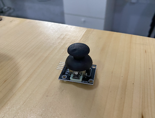
The Joystick is an example of an analog input that sends out a change in voltage based on the change in X and Y positions. In more simple terms, the when you move the joystick the voltage that is sent to the microcontroller changes and this is seen as different readings in the programming software.
For the Joystick in the datasheet it depicts how to connect it to an Arduino UNO however the same connection ports can be found in the Adafruit sense. The Analog pin and the Digital pins can be found in relatively similar locations in the Adafruit board. However Arduino UNO works on a 5V while the Adafruit operates on a 3.3V, which shouldn’t pose as an issue
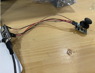
After I connected each pin to its designated pin in the board with the use of a wire I ran the pre-made code in the datasheet to test it out. I had to change add a library to the code since the Adafruit microcontroller requires me to do so and to also change the X and Y pin inputs to A0 and A1.
#include <SoftwareSerial.h>


const int SW_pin = 2; // digital pin connected to SW
const int X_pin = A0; // analog pin connected to VRx
const int Y_pin = A1; // analog pin connected to VRy
void setup() {
 pinMode(SW_pin, INPUT);
 digitalWrite(SW_pin, HIGH);
 Serial.begin(9600);
}
void loop() {
 Serial.print("X: ");
 Serial.print(analogRead(X_pin));
 Serial.print(" Y: ");
 Serial.print(analogRead(Y_pin));
 Serial.print(" Z: ");
 Serial.println(digitalRead(SW_pin));
 delay(250);
}
Arduino Car
For this week I was inspired by a pinterest post that portrayed a car which was controlled by the Arduino uno microcontroller. I wanted to take up the challenege of assembling such a thing as well as having it operating (moves when given a command.)
I followed this youtube tutorial and had already purchased the car assembly kit.
I started off by following the instruciton on the kit and assembled the bottom motors and the wheels onto the acrylic board. Following that step, I attached the designated wires to the H bridge. The motor wires went into the H bridge and the H bridge itself was connected to the Arduino Uno.
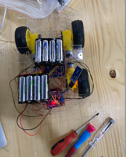
After it was successfully assembled I screwed in the battery pack to the top of the board and connected its designated wires to the microcontroller.
I then used the pre-made code that was already available with the youtube video and decided to run the code.
Unfortunately, the car does not pair with my iPhone so I had to use an andrioid tablet to test it out first. It did successfully work however the batteries were not powerful enough to supply the whole device. A change of batteries were in need.
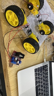
Here is an image of the car when I first assembled it with the H-bridge.
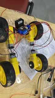
As you can see the motor wires on one wheel was attached to the same side as the one on its side and the other wheel were on their on respective side. (That is to ensure that when the command is given certain wires on one side turned to the right/left)
This video shows when I had to test out one of the motors to make sure everything was working and what we had discovered was that the two motors on the side were on different pages on one book so I had to refer back to the it’s specific logic table to correct that issue. The solution was that we just needed to switch commands for two of the wheels to prevent them from spinning when given the forward command.
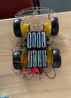
Here are images before and after its final assembly which consisted of fixing in screws and taping braided wires.
#include <SoftwareSerial.h>

SoftwareSerial mySerial(0, 1); // RX | TX
int command ;
void setup() {
   Serial.begin(9600);
   mySerial.begin(9600);
   Serial.println("You're connected via Bluetooth");
   pinMode(13,OUTPUT);   //left motors forward
   pinMode(12,OUTPUT);   //left motors reverse
   pinMode(11,OUTPUT);   //right motors forward
   pinMode(10,OUTPUT);   //right motors reverse

}

void loop() {
   if (mySerial.available())
   {
    command=(mySerial.read());
    if (command=='F')
    {
      Serial.println("Forward");
      digitalWrite(13,LOW);
      digitalWrite(12,HIGH);
      digitalWrite(11,HIGH);
      digitalWrite(10,LOW);

    }

        else if (command=='B')
    {
      Serial.println("Reverse");
      digitalWrite(13,HIGH);
      digitalWrite(12,LOW);
      digitalWrite(11,LOW);
      digitalWrite(10,HIGH);
    }

        else if (command=='L')
    {
      Serial.println("Left");
      digitalWrite(13,LOW);
      digitalWrite(12,LOW);
      digitalWrite(11,HIGH);
      digitalWrite(10,LOW);
    }

        else if (command=='R')
    {
      Serial.println("Right");
      digitalWrite(13,LOW);
      digitalWrite(12,HIGH);
      digitalWrite(11,LOW);
      digitalWrite(10,LOW);
    }

        else if (command=='S')
    {
      Serial.println("Stop");
      digitalWrite(13,LOW);
      digitalWrite(12,LOW);
      digitalWrite(11,LOW);
      digitalWrite(10,LOW);
    }
   delay(30);
  }
}