Robotic Arm Car
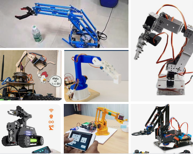
I was very much inspired by multiple creations online of other individual’s creation of a robotic arm car. The car is to a great extent similar to the one that I assembled during the input and output week here at FabLab. However like I mentioned the car was simply assembled not designed, laser cut and experimented on wether or not it fits its assigned screws and nuts. The location of the cables as well were all clearly illustrated in the instructions manual that came with the car when I bought it and as a challenge I wanted to be able to make it and assemble it from scratch.
Research
From scratch isn’t a term that should be used lightly and in this case I’ll define it as: made by me while being inspired by others. It would be plagiarism if I claim that I designed it all by myself and out of the corner of my mind a light bulb turned on and my hands started creating the sketches in Fusion360. However I can safely say that I used other people’s designs and adjusted them to fit my own idea on how I would want it to look like.
Useful links
The Steps
For the acrylic car board, that houses the motors, Arduino Uno and H-bridge I was inspired by a design file that I saw online but it was extremely similar to the one that I bought therefore for my own board I used Cuttle to make a board with the same dimensions but with generally a lot less holes since they weren’t truly necessary for my requirements.
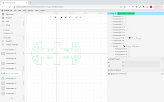
I used the tools Mirror repeat and Boolean difference to perform the actions on one side and have them automatically happen on the other side within the same distance and cut out the openings that I need.
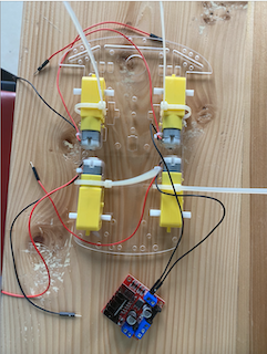
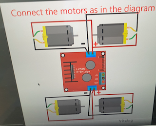
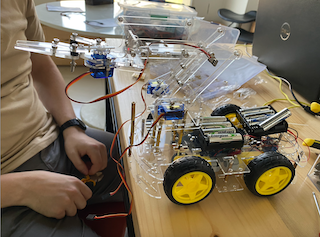
After laser cutting the acrylic board I used nylon cable wires to secure the motors in place and connect the respective wires to their position in the H-bridge. This step and all the ones following it in regards to the car assembly were fairly easy and straight forward since I’ve performed them beforehand in my previous car assembly.
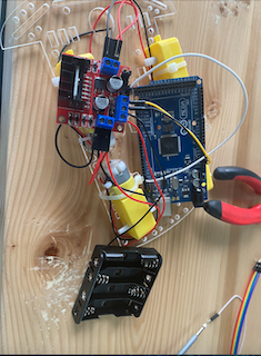
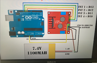
After all the motors were placed in position it was time to check if they worked or not by attaching them to the Arduino Uno and using a simple code to check. Before doing that though and before their initial assembly even we placed a single battery in the between the red and black wiring just to be assured that the motors that I was assembling were in fact functional. Below is a schematic that I followed from a youtube video online. The video itself can be found in the useful links tab at the top of this page.
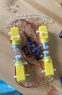
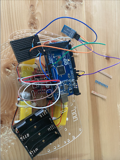
Following the schematic and I was successfully able to achieve proper assembly. I tested out the motors and they were in fact fully functional which gave me the green light to try and wireless control them like I did last time. Below is the image of when I attached the bluetooth module to the Arduino Uno board and since the connection ports were limited I used a breadboard to help ease it in that regard.
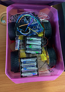
And finally here is the final car in its box that I use to store it in the lab. A perfect fit for a perfect car.
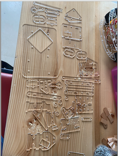
Now onto the arm, I used a handful of design options from Ben Gary the original creator of the meArm. He has multiple version of the meArm and I used different designs from different versions to make what I envisioned come to life. My main concern was the gripper since I wanted a sizably big and wide gripper to be able to manouver it as I please. I laser cut all the pieces from this design file However I ended up not using most of them and modifying and recutting the ones that I actually did need. If I could go back in time I would design the pieces to fit a particular set of screws that are readily available in the lab.
I required two days and a total of 6 hours to fully assemble the arm together. I had no reference point as to what I wanted it to look like nor did the online references make a lot of sense.
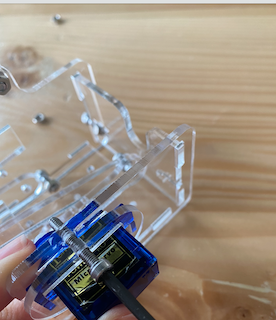
As I was assembling a major issue that I encountered was the placement of the servo motors. Most of the design files showed 4 motors: left and right, the gripper and an additional one for moving the base left and right. However for my project I did not require the fourth base motor since the car itself can be programmed to move left or right. After a set of trials I was able to make do with their assembly to a an extent that was functional.
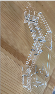
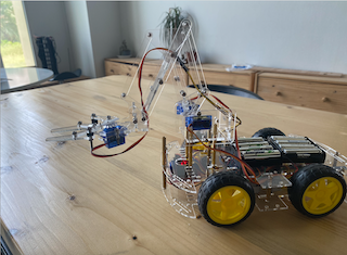
Below is the robotic arm fully assembled and connected to the Arduino car.
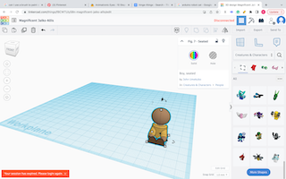
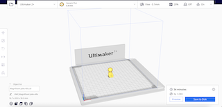
In order to incorporate a 3d design to my project I 3d printed a chracter from TinkerCAD to act as the controller inside the car. Just for some added character.
Materials
| Qty | Description | Link |
|---|---|---|
| 4 | Wheels | https://www.instagram.com/p/CYtyinAsx_d/?hl=en |
| 4 | DC motors | https://www.instagram.com/p/CYtyinAsx_d/?hl=en |
| 1 | H-bridge | https://www.instagram.com/p/CfoZRMOMe_m/?hl=en |
| 1 | Arduino Uno | https://www.instagram.com/p/CDhK1HuMZMZ/?hl=en |
| 2 | Battery Pack | https://www.instagram.com/p/B6jDF-9A7Br/?hl=en |
| 1 | Bluetooth module | https://www.instagram.com/p/CAGc_P0HvbD/?hl=en |
| 3 | Servo motors | https://www.instagram.com/p/B58BhMxArLy/?hl=en |
| A pack | jumper wires | https://www.amazon.in/Jumper-Wires-Male-female-Pieces/dp/B00ZYFX6A2?th=1 |
Code
Below is the code that I used for programming the car and the arm simultaneously.
To test out the Servo motors I used the Sweep code that was built in to the software in the examples tab. After two days worth of trial and error I was finally able to obtain the angles required to make the robotic arm move up and down to my desired height.
#include <SoftwareSerial.h>
#include <Servo.h>

int pos = 0;
int pos1 = 0;
int pos2 = 0;
Servo myservo;
Servo myservo1;
Servo myservo2;
    bool terminateState = 0;
    bool terminateState1 = 0;
    bool terminateState2 = 0;
    bool terminateState3 = 0;


SoftwareSerial mySerial(0, 1); // RX | TX
int command ;
void setup() {
   Serial.begin(9600);
   mySerial.begin(9600);
   Serial.println("You're connected via Bluetooth");
   pinMode(13,OUTPUT);   //left motors forward
   pinMode(12,OUTPUT);   //left motors reverse
   pinMode(11,OUTPUT);   //right motors forward
   pinMode(10,OUTPUT);   //right motors reverse
   myservo.attach(7);
   myservo1.attach(6);
   myservo2.attach(5);
}

void loop() {
   if (mySerial.available())
   {
    command=(mySerial.read());
    if (command=='F')
    {
      Serial.println("Forward");
      digitalWrite(13,LOW);
      digitalWrite(12,HIGH);
      digitalWrite(11,HIGH);
      digitalWrite(10,LOW);

    }

        else if (command=='B')
    {
      Serial.println("Reverse");
      digitalWrite(13,HIGH);
      digitalWrite(12,LOW);
      digitalWrite(11,LOW);
      digitalWrite(10,HIGH);
    }

        else if (command=='L')
    {
      Serial.println("Left");
      digitalWrite(13,LOW);
      digitalWrite(12,LOW);
      digitalWrite(11,HIGH);
      digitalWrite(10,LOW);
    }

        else if (command=='R')
    {
      Serial.println("Right");
      digitalWrite(13,LOW);
      digitalWrite(12,HIGH);
      digitalWrite(11,LOW);
      digitalWrite(10,LOW);
    }

        else if (command=='S')
    {
      Serial.println("Stop");
      digitalWrite(13,LOW);
      digitalWrite(12,LOW);
      digitalWrite(11,LOW);
      digitalWrite(10,LOW);
    }


    else if (command=='O' && terminateState == 0)
    {
      Serial.println("Open Gripper");
      for (pos1 = 0; pos1 <= 100; pos1 += 1) {
      myservo1.write(pos1);
      delay (10);
      terminateState  = 1;
      terminateState1 = 0;
    }
    }


    else if (command=='K' && terminateState1 == 0)
    {
      Serial.println("Close Gripper");
      for (pos1 = 100; pos1 >= 0; pos1 -= 1) {
      myservo1.write(pos1);
      delay (10);
      terminateState  = 0;
      terminateState1 = 1;
    }
    }

else if (command=='U')
    {
      Serial.println("Up");
      myservo.write(-120);
     myservo2.write(100);
        delay (10);
    }


else if (command=='D')
    {
      Serial.println("Down");
      myservo.write(120);
     myservo2.write(-100);
        delay (10);
    }


  }
}
Demo Videos
Hero Shot
Questions about my proposed final project
Propose a final project masterpiece that integrates the range of units covered, answering:
-
What will it do? It should stimulate the ecpected motion of an arm as it grips objects while also being able to move successfuly and by that I mean for example that when it is commanded by F it moves Forward etc.
-
Who’s done what beforehand? An exact replica of what I plan to do can be found all over the internet. It certainly isn’t a breakthrough idea nor do I claim for it to be. As an absoulate beginner I truly wanted to push myself and try my best to replicate what is already out there with my own twist to it.
- What will you design? I’ll try to design everything that is already available from scratch. Wether it’s the acrylic board that the car lays on, or the small bits and pieces that make up the arm. I will surely be using what is already out there as a draft to work upon
-
What materials and components will be used? mostly acrylic for the body structure and the rest would be pre-existing sensors and pieces.
-
Where will it come from? I’ll making use of the materials available at FabLab
-
How much will they cost? An estimate of the price cannot be provided at this time because the materials have not yet been disclosed
-
What parts and systems will be made? The car’s structural body and the arm pieces.
-
What processes will be used? Laser cutting and embedded programming alongside input and output operations
-
What questions need to be answered? How to code a robotic arm by using an Arduino board and how will I be able to synchronize both the movement of the arm and the motion of the car
-
How will it be evaluated? Based on the motions accuracy and the demonstrative purposes.
Your project should incorporate 2D and 3D design, additive and subtractive fabrication processes, electronics design and production, embedded microcontroller interfacing and programming, system integration and packaging Where possible, you should make rather than buy the parts of your project Projects can be separate or joint, but need to show individual mastery of the skills, and be independently operable
Design Files
Acrylic board for the car as dxf
Acrylic board for the car as svg
License
All the files are free to use and assemble as you wish. I do not own nor claim to own any file unless stated otherwise. All credit goes to the original designers.