5. Embedded Programming
This week we dealt with microcontroller boards. A microcontroller board is essentially a small computer. A plug for air-conditioners is an example of an alternating current because of its high voltage it is considered dangerous. DC currents are battery operated. During this week we’ll be dealing with DC currents.
A microcontroller is something we can use to control the flow of a current to a designated object. It’s the brain that decides to turn on or off a current based on what we program it to do.
- Inputs and outputs can be connected to a microcontroller each with different specs.
- Arduino Uno is a very common and baseline microcontroller board that is used.
- At the top and bottom of the Arduino Uno board are pins where we could insert the inputs and outputs
- Power can be given to the board through the pins on the side when its connected to a computer
- The brain is most commonly a black chip that is in the center
Group Assignment
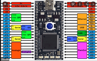
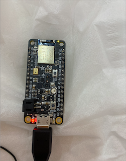
We were given the microcontroller shown below and tasked to identify its following characteristics :
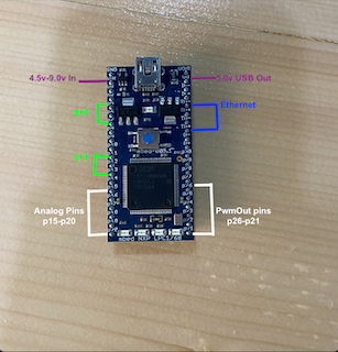
- What type of microcontroller is it: mbed-005.1
- Number of pins: 40 pins
- Type of pins : Analog and PMW output
- Power source required / amount of voltage: 5V USB or 4.5-9V supply, 60-120mA (Vin)
- Type of Sensors that can be added: Temperature, Distance, Light, Acceleration, GPS coordinates and heart rate.
- Languages that are used to program the microcontroller : C and C++
Link to the entire classes’ Group Assignment where we compared different types of microcontrollers
Individual Assignment
Pins in a microcontroller are used to interface it with external parts. These pins will be very useful to use in the Input and Output week.
- Analog pins can be connected to analog sensors
- Digital pins can be connected to digital inputs and outputs
For this week we controlled the light switch with programming. By turning it on and off in order to understand the microcontroller itself.
Arduino IDE
Steps on how I step up my microcontroller 'Adafruit feather Bluefruit Sense' :
1. I downloaded it form this link: https://www.arduino.cc/en/software/2. After it was installed I followed the steps in this link: https://learn.adafruit.com/adafruit-feather-sense/arduino-support-setup to help me set it up to my Adafruit Feather Bluefruit Sense microcontroller.
3. I went to preferences in the menu tab and added the designated link to the URL addition option
4. I installed Adafruit Bluefruit nRF52832 Feather and that took a while to install but it eventually did install
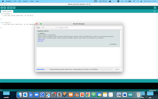
Here is an image as I set up Arduino by adding it’s link in the Additional Board Manager URL
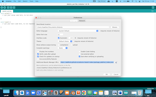
It was taking alot of time to download the Adafruit Bluefruit nRF52832 Feather which was the board that we were instructed to add
After it was succesfully installed I decided to run the pre-exsiting example of blink into the board before I went ahead and wrote a code myself. Here is the pre-made blink code:
/*
  Blink

  Turns an LED on for one second, then off for one second, repeatedly.

  Most Arduinos have an on-board LED you can control. On the UNO, MEGA and ZERO
  it is attached to digital pin 13, on MKR1000 on pin 6. LED_BUILTIN is set to
  the correct LED pin independent of which board is used.
  If you want to know what pin the on-board LED is connected to on your Arduino
  model, check the Technical Specs of your board at:
  https://www.arduino.cc/en/Main/Products

  modified 8 May 2014
  by Scott Fitzgerald
  modified 2 Sep 2016
  by Arturo Guadalupi
  modified 8 Sep 2016
  by Colby Newman

  This example code is in the public domain.

  https://www.arduino.cc/en/Tutorial/BuiltInExamples/Blink
*/

// the setup function runs once when you press reset or power the board
void setup() {
  // initialize digital pin LED_BUILTIN as an output.
  pinMode(LED_BUILTIN, OUTPUT);
}

// the loop function runs over and over again forever
void loop() {
  digitalWrite(LED_BUILTIN, HIGH);   // turn the LED on (HIGH is the voltage level)
  delay(1000);                       // wait for a second
  digitalWrite(LED_BUILTIN, LOW);    // turn the LED off by making the voltage LOW
  delay(1000);                       // wait for a second
}
I decided to make my own code by following the following youtube video and here are the results below:
Hero video:
// the setup function runs once when you press reset or power the board
void setup() {
  // initialize digital pin LED_BUILTIN as an output.
  pinMode(LED_BUILTIN, OUTPUT);
}

// the loop function runs over and over again forever
void loop() {
  digitalWrite(LED_BUILTIN, HIGH);   // turn the LED on (HIGH is the voltage level)
  delay(300);                       // wait for a second
  digitalWrite(LED_BUILTIN, LOW);    // turn the LED off by making the voltage LOW
  delay(300);                       // wait for a second
}
Lecture Notes for writing a code
In the Void Setup we determine what the pinmode is for one of the pins. The LED light can be connected to a particular number of pin. The LED light is considered an output therefore we write the code as (LED,output). For a pin number (pinnumber, output) If the pin is A5 for example the code will be (A5, output)
Void Loop is the code that actually runs, For (LED,High) we are turning on the light. While (LED,Low) means that the LED will turn off.
- High = On
- Low = Off
- Delay is duration between on and off
Here is a code for changing the LED light on and off for a different time
// the setup function runs once when you press reset or power the board
void setup() {
  // initialize digital pin LED_BUILTIN as an output.
  pinMode(LED_BUILTIN, OUTPUT);
}

// the loop function runs over and over again forever
void loop() {
  digitalWrite(LED_BUILTIN, HIGH);   // turn the LED on (HIGH is the voltage level)
  delay(2000);                       // wait for a second
  digitalWrite(LED_BUILTIN, LOW);    // turn the LED off by making the voltage LOW
  delay(100);                       // wait for a second
}
Below is a longer code which uses different timings and is longer than the rest.
// the setup function runs once when you press reset or power the board
void setup() {
  // initialize digital pin LED_BUILTIN as an output.
  pinMode(LED_BUILTIN, OUTPUT);
}

// the loop function runs over and over again forever
void loop() {
  digitalWrite(LED_BUILTIN, HIGH);   // turn the LED on (HIGH is the voltage level)
  delay(2000);                       // wait for a second
  digitalWrite(LED_BUILTIN, LOW);    // turn the LED off by making the voltage LOW
  delay(100);                       // wait for a second

 digitalWrite(LED_BUILTIN, HIGH);   // turn the LED on (HIGH is the voltage level)
  delay(1000);                       // wait for a second
  digitalWrite(LED_BUILTIN, LOW);    // turn the LED off by making the voltage LOW
  delay(200);                       // wait for a second


 digitalWrite(LED_BUILTIN, HIGH);   // turn the LED on (HIGH is the voltage level)
  delay(500);                       // wait for a second
  digitalWrite(LED_BUILTIN, LOW);    // turn the LED off by making the voltage LOW
  delay(1000);                       // wait for a second


 digitalWrite(LED_BUILTIN, HIGH);   // turn the LED on (HIGH is the voltage level)
  delay(1000);                       // wait for a second
  digitalWrite(LED_BUILTIN, LOW);    // turn the LED off by making the voltage LOW
  delay(500);                       // wait for a second


digitalWrite(LED_BUILTIN, HIGH);   // turn the LED on (HIGH is the voltage level)
  delay(3000);                       // wait for a second
  digitalWrite(LED_BUILTIN, LOW);    // turn the LED off by making the voltage LOW
  delay(2000);                       // wait for a second


}
TinkerCAD Tutorial
Other than 3D designs TinkerCAD is actually very useful as a beginner friendly circuit stimulation for microcontrollers.
Steps for setting up an Arduino circuit on TinkerCAD :
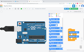
1. Open TinkerCAD circuits2. Drag and drop Arduino Uno R3
3. Then press on code at the top right corner
4. The pre-made code will appear and you can immediately start stimulation.
5. You can convert the code into text which can use in another software by switching blocks on the left to text.
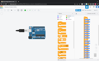
Below is the initial pre-made stimulation that we ran in TinkerCAD
For the next steps of the codes we were introduced to Morsecode which we will use to design circuits in TinkerCAD
. = Low
-= High
For my example I choose the word ‘ship’ and de-coded it based on the configuration that we were given in class.
dot = 0.5 sec
dash = 1 sec
gap between dot and dash = 0.5 sec (off)
gap between letter = 2 sec off
‘ship’ in morse code is: … .... .. .–.
0.5 sec
0.5 sec (off)
0.5 sec
0.5 sec (off)
0.5 sec
2 sec off
0.5 sec
0.5 sec (off)
0.5 sec
0.5 sec (off)
0.5 sec
0.5 sec (off)
0.5 sec
2 sec off
0.5 sec
0.5 sec off
0.5 sec
2 sec off
0.5 sec
0.5 sec off
1 sec
0.5 sec off
1 sec
0.5 sec off
0.5 sec
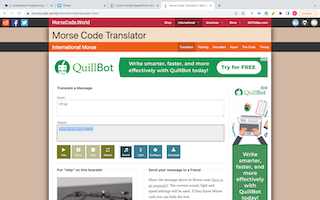
Here is the Translation of the word ship from an accredited google search morse code translator (it was the first one that popped up in the search option, as accredited as accredations can get)
I then re-coded my morse code into TinkerCAD. I used the repeat option for some of the codes that were in repeat.
After setting up the code in TinkerCAD I downloaded it into Arduino to upload it into my microcontroller and here is downloaded code below:
// C++ code
//
int counter;

int counter2;

void setup()
{
  pinMode(LED_BUILTIN, OUTPUT);
}

void loop()
{
  digitalWrite(LED_BUILTIN, HIGH);
  for (counter = 0; counter < 2; ++counter) {
    delay(500); // Wait for 500 millisecond(s)
    digitalWrite(LED_BUILTIN, LOW);
    delay(500); // Wait for 500 millisecond(s)
  }
  digitalWrite(LED_BUILTIN, HIGH);
  delay(500); // Wait for 500 millisecond(s)
  digitalWrite(LED_BUILTIN, LOW);
  delay(2000); // Wait for 2000 millisecond(s)
  for (counter2 = 0; counter2 < 3; ++counter2) {
    digitalWrite(LED_BUILTIN, HIGH);
    delay(500); // Wait for 500 millisecond(s)
    digitalWrite(LED_BUILTIN, LOW);
    delay(500); // Wait for 500 millisecond(s)
  }
  digitalWrite(LED_BUILTIN, HIGH);
  delay(500); // Wait for 500 millisecond(s)
  digitalWrite(LED_BUILTIN, LOW);
  delay(2000); // Wait for 2000 millisecond(s)
  digitalWrite(LED_BUILTIN, HIGH);
  delay(500); // Wait for 500 millisecond(s)
  digitalWrite(LED_BUILTIN, LOW);
  delay(500); // Wait for 500 millisecond(s)
  digitalWrite(LED_BUILTIN, HIGH);
  delay(500); // Wait for 500 millisecond(s)
  digitalWrite(LED_BUILTIN, LOW);
  delay(2000); // Wait for 2000 millisecond(s)
  digitalWrite(LED_BUILTIN, HIGH);
  delay(500); // Wait for 500 millisecond(s)
  digitalWrite(LED_BUILTIN, LOW);
  delay(500); // Wait for 500 millisecond(s)
  digitalWrite(LED_BUILTIN, HIGH);
  delay(1000); // Wait for 1000 millisecond(s)
  digitalWrite(LED_BUILTIN, LOW);
  delay(500); // Wait for 500 millisecond(s)
  digitalWrite(LED_BUILTIN, HIGH);
  delay(1000); // Wait for 1000 millisecond(s)
  digitalWrite(LED_BUILTIN, HIGH);
  delay(500); // Wait for 500 millisecond(s)
  digitalWrite(LED_BUILTIN, HIGH);
  delay(500); // Wait for 500 millisecond(s)
}
Challenges:
Easy
Prompt: Blink your led but have your blink delay periods be randomized values between 1 second and 5 seconds
The Solution :
1. I used TinkerCAD to add a code brick that allows me to randomize the values for my delay periods.2. I drag and drop Arduino Uno into the workplace and place the random value brick
3. After I allowed it to place random values between 1 and 5 seconds; I ran the stimulation to preview the code
4. I then downloaded the code to Arduino IDE to load onto my microcontroller
5. I uploaded my code onto the microcontroller and documented by results in the video below.
  // C++ code
  //
  void setup()
  {
    pinMode(LED_BUILTIN, OUTPUT);
  }

  void loop()
  {
    digitalWrite(LED_BUILTIN, HIGH);
    delay(1000 * random(1, 5 + 1)); // Wait for 1000 * random(1, 5 + 1) millisecond(s)
    digitalWrite(LED_BUILTIN, LOW);
    delay(1000 * random(1, 5 + 1)); // Wait for 1000 * random(1, 5 + 1) millisecond(s)
  }
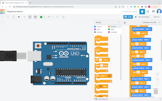
This image depicts my work on the coding through using the bricks feature in circuits on TinkerCAD
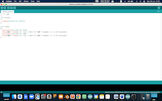
Here is the code after I transfered it to Arduino IDE
Medium
Prompt : pre code your microcontroller to send a Morse code 1 word message and challenge a friend, family member, your colleagues or your instructor to figure it out.
dot = 0.5 second light on.
dash=1 second light on.
gap between dots and dashes=0.5 second light off.
gap between letters=2 second light off
The Solution :
1. I choose the word help (very original) and used a Morse code translator from google to help translate it to morse code2. It translated to : .... . .-.. .--.
3. I then encoded it in morse code and got the following:
0.5 second light on.
0.5 second light off
0.5 second light on.
0.5 second light off
0.5 second light on.
0.5 second light off
0.5 second light on.
2 second light off
0.5 second light on.
2 second light off
0.5 second light on.
0.5 second light off
1 second light on.
0.5 second light off
0.5 second light on.
0.5 second light off
0.5 second light on.
2 second light off
0.5 second light on.
0.5 second light off
1 second light on.
0.5 second light off
1 second light on.
0.5 second light off
0.5 second light on
4. I then used the morse code to code my Arduino on TinkerCAD. I used the repeat tool to help me become more efficient
5. I downloaded the code from TinkerCAD to Arduino IDE and uploaded it onto my microcontroller and documented the results as the video is shows below
6. side note : no one was able to to figure it out :) although it was extremely on topic
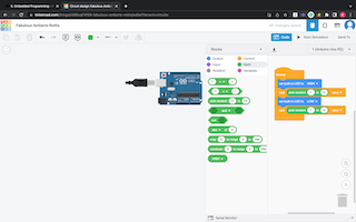
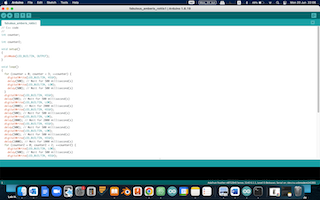
Here is the extremely long code for the word ‘help’ I used the repeat feature to quicken my work flow
After I transferred my
Hard
Prompt: you select the duration of the light being on and off while the program is running by entering it in the serial monitor. Write a code that takes the data from the serial monitor and delays by that amount of time.
int ledPin = LED_BUILTIN; // declare LED_BUILTIN as ledpin
int numBlinks; // variable to store the number of blinks
String LedOnMessage = "LED_BUILTIN is turned on"; // this is a string with information
String LedOffMessage = "LED_BUILTIN is turned off"; // this is a string with information
void setup()
{
  pinMode(ledPin, OUTPUT);  // set LED_BUILTIN as output pin
  digitalWrite(ledPin, LOW); // set the pin value on low at the begin
  Serial.begin(9600);
}
void loop()
{
  Serial.println("How Many Times Do You Want the Red LEDs to blink?"); //Prompt User for Input
  while (Serial.available() == 0) {
    // Wait for User to Input Data
  }
  numBlinks = Serial.parseInt(); //Read the data the user has input
  for (int counter = 1; counter <= numBlinks; counter++) {
    Serial.println(LedOnMessage);
    digitalWrite(ledPin, HIGH);
    delay(1000);
    Serial.println(LedOffMessage);
    digitalWrite(ledPin, LOW);
    delay(1000);
  }
  Serial.print("The user has choosen the number:");
  Serial.println(numBlinks);
  Serial.println(" ");
}
The Solution :
1. I searched on google for what a serial monitor is and found what I needed in this website https://www.oreilly.com/library/view/arduino-cookbook/9781449399368/ch04.html2. I used the code example that they provided by had to change the output to LEDBUILTIN since my target led was the one that was built in the microcontroller not an external one similar to the one in the example
3. The blink rate was also set to change based on what I write it to be in the serial monitor
4. Serial monitor can be found in the Tools option in the menu bar
5. For when I tested it out I set the LED to blink 5 times by entering the number 5 in the serial monitor and seeing what happens, it has successfully delivered my command by blinking 5 times and then asking me again how many times I would want it to blink.
Real life Application: As general as this might seem, it is actually quite helpful for traffic control officer's especially during certain circumstances. When I say traffic I'm actually thinking of airline traffic control since the officers can communicate with the pilot based on the number of blinks. In pre-google times I can actually see how this is extremely helpful when sending morse codes for ships since they didn't have an instant translator.
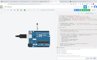
I used the stimulation option in TinkerCAD first to run my code to doublecheck if it works first before running it in Arduino IDE and on my actual microcontroller. As proven it has yielded it’s promised results :)
Python
We were required to download Circuit Pyhton and mu editor.
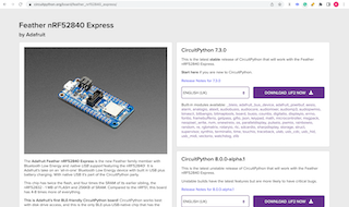
I followed this link which helped load adafruit circuit python onto my micrcontoller file.
Python is another software to code microcontrollers similar to Arduino and TinkerCAD. After it was downloaded I added the code for blinking that I found in this link
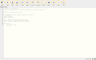
Here is the code that I ran in Pyhton to allow my built in LED to blink: