2. Computer Aided design
During this week, I learned the fundamentals of CAD softwares and how to utilize a combination of features to build 2D and 3D objects from the scratch.
2D
Forms with two dimensions, such as width and height, are referred to as 2D shapes. A rectangle or a circle are two-dimensional shapes. Because 2D objects have no depth, they cannot be physically touched; a 2D shape is absolutely flat.
Inkscape
Inkscape is a free and open-source vector graphics editor that primarily works with the Scalable Vector Graphics (SVG) format. Importing and exporting data in other formats is possible. Inkscape is capable of rendering simple vector shapes and text.
First I downloaded Inkscape on my device to start working on my project. I then looked up a Youtube Tutorial to guide me around Inkscape as it was my first time using it.
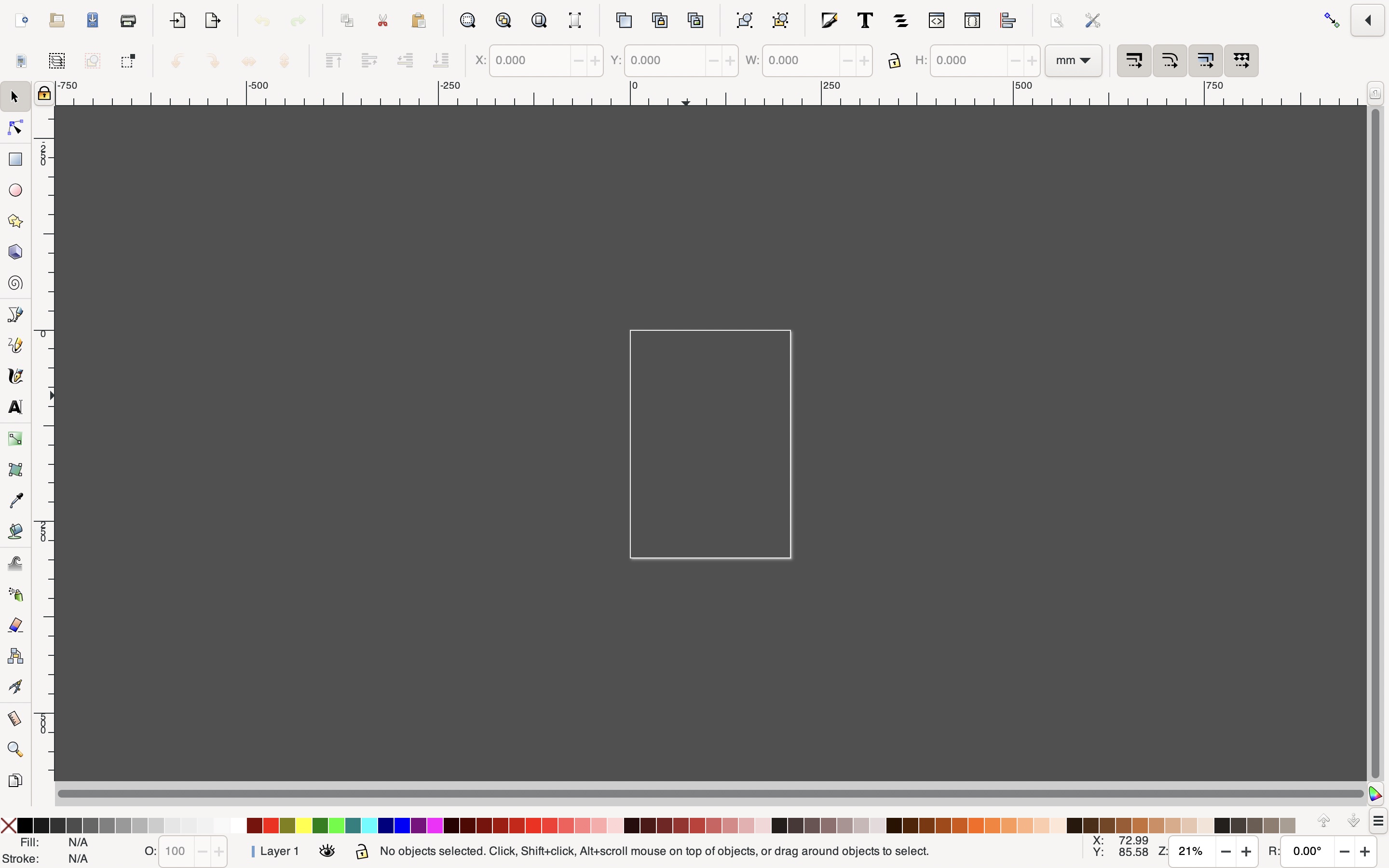
1 - First i opened a new document, where i will perform the designing process.
2 - To begin, I chose the circle icon in the left panel and dragged it across the screen to make a circle, after which I entered in the desired measurement for the circle. After that, I reduced the opacity of the circle to make it more transparent, and I right-clicked it to duplicate it in a lower size than the original.
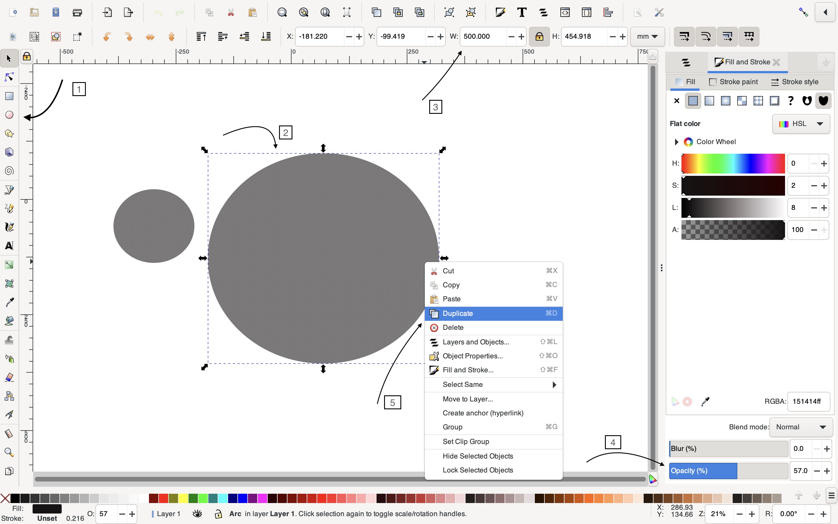
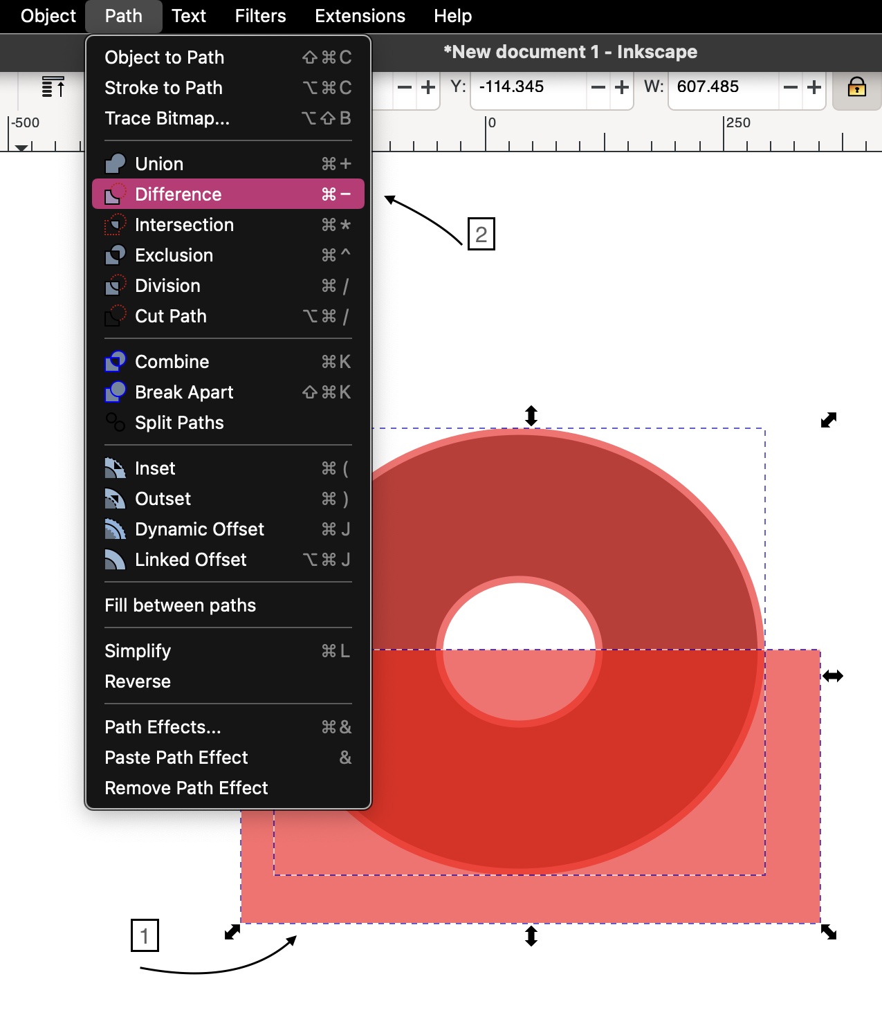
After that, I selected both circles and proceeded to the “Align” panel on the right, where I opted to center them vertically and horizontally. I moved to Path> Difference while still selecting the circles, which created a hole in the middle of the circle, resulting in a donut-like pattern.
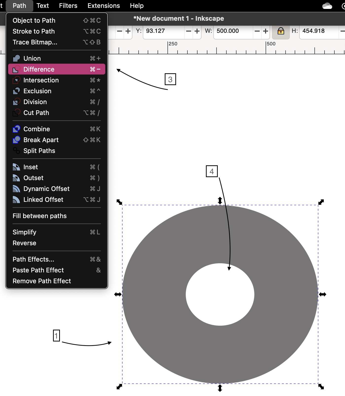
3 - I then duplicated the larger circle and filled it with a red color, then typed the command Command> 0 on my keyboard, which caused the larger circle outline to slightly grow in size, allowing it to pass over the primary circle border.
Only after that, I used the right panel’s square icon to draw a square on the bottom half of the donut figure, then used Path> Difference to merge the two shapes, resulting in the shape below.

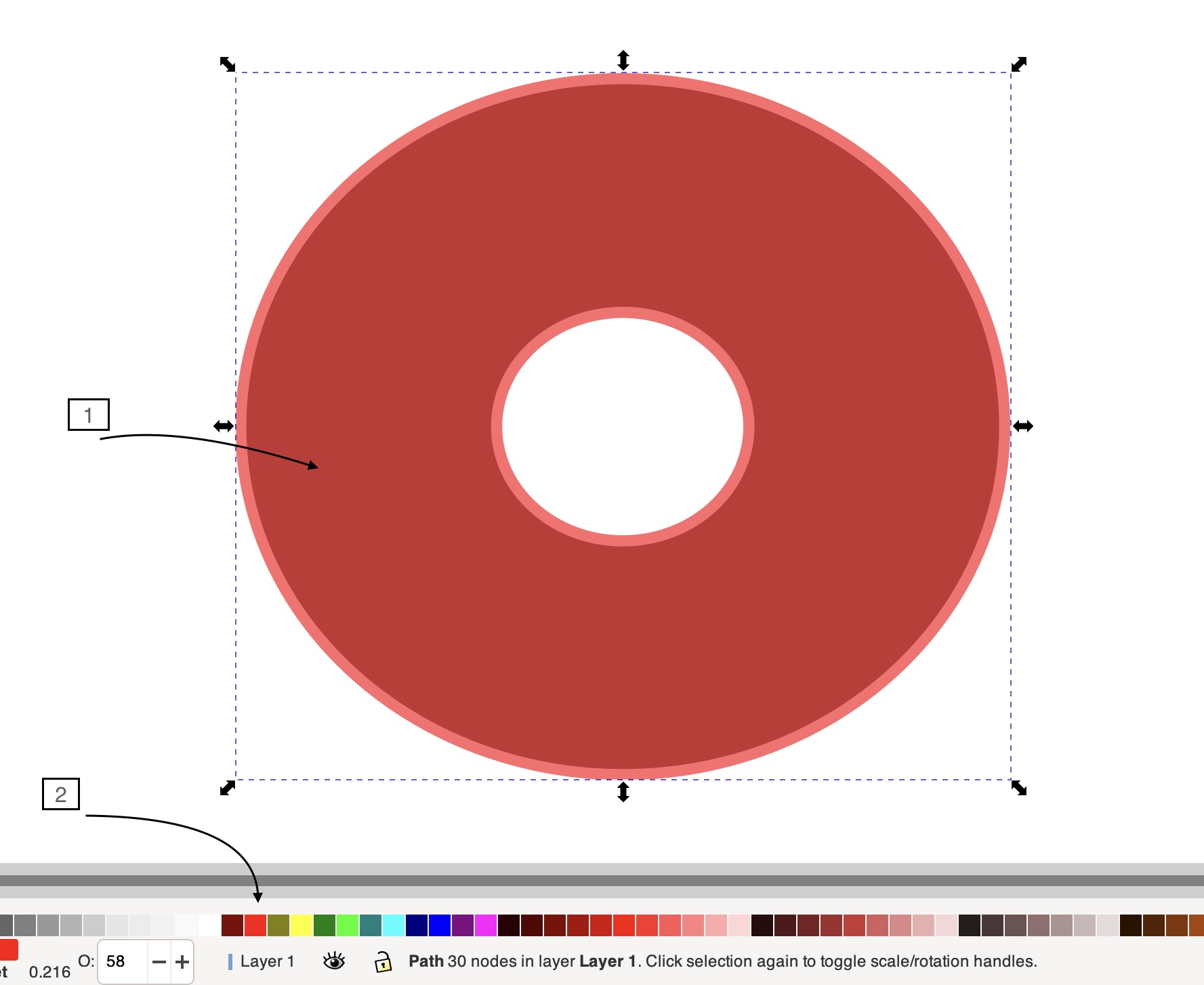
4 - I used the adjusment cursor to choose the red half and then clicked on the Nodes button, which revealed nodes on the shape, making it easier to adjust the shape at different angles to get the dripping effect. Of course I then did the exact same thing on the other side.
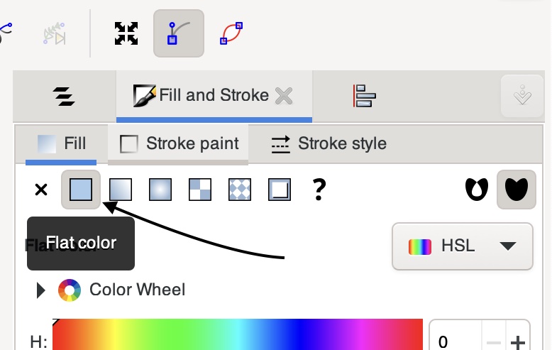
To make the design more realistic, I modified some of the colors and reduced the transparency.

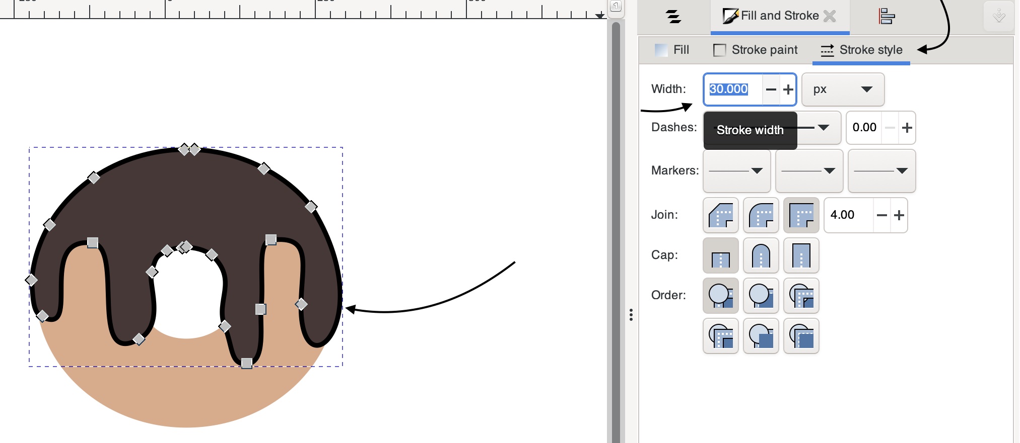
After which I went to the right panel> Fill and Stroke> Fill> Flat color and selected the donut’s icing, then moved to Stroke style and entered the width of the outline I wanted, which gave the donut a more defined icing.
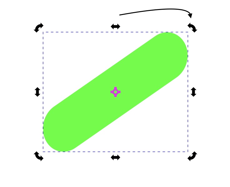
5 - I started by selecting the rectangle icon from the left panel and then clicking and moving my cursor while holding to produce a rectangular shape in the last phase where I applied the sprinkles to the donut. While selecting the modifying cursor on the left panel, I clicked on the form I had just drawn, then on the circle on the corner and dragged it to the bottom to give it the rounded corners figure.
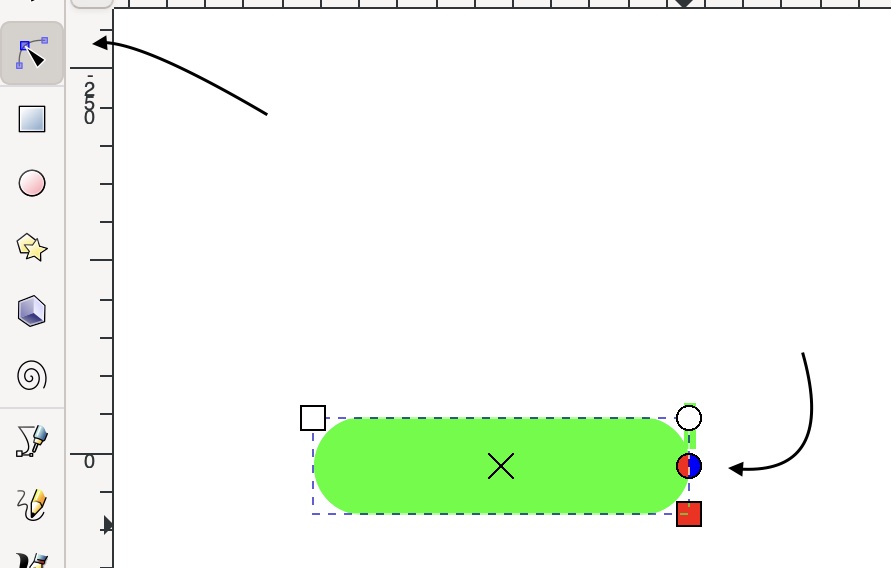
I clicked on the form again to bring up more options, and I titled the shape at 45 degrees using the corner tilting option.
I then duplicated the shape several times, altering some of the colors to make it more vibrant and switching the tilit to the opposite side.
Final Results

Click here to download the file.
Smartdraw
SmartDraw is a diagramming software that may be used to create flowcharts, organizational charts, mind maps, project charts, and other business visualizations. SmartDraw is available in two editions: online and downloaded for Windows desktop.
Using Smartdraw i designed a one bedroom apartment, from scratch.
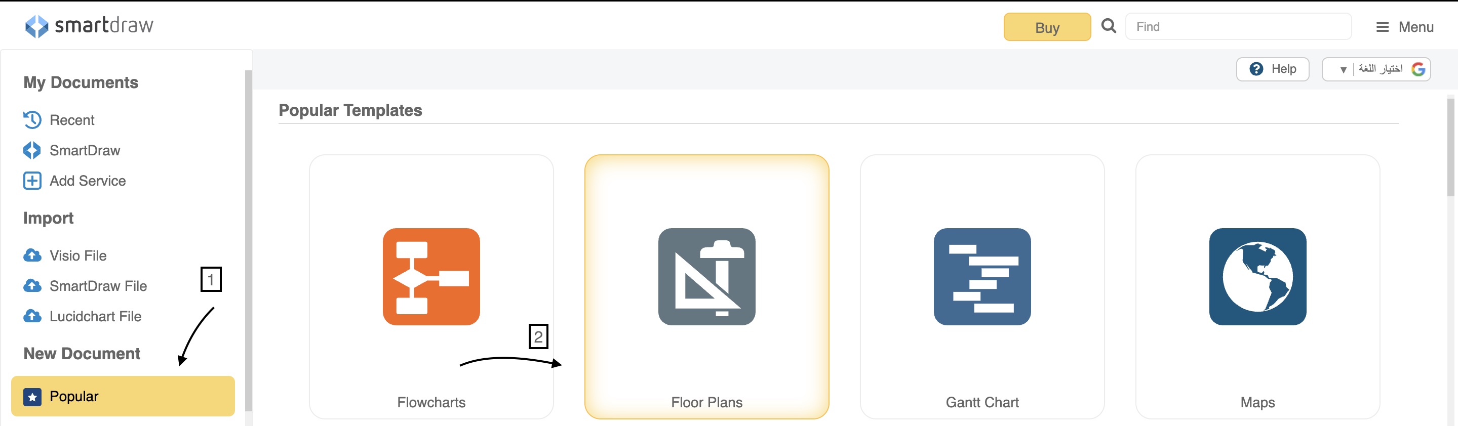
1 - To be able to utilize Smartdraw, I first registered an account on the online version. I then went on to look for a template that I could use to begin designing my apartment layout. I first clicked on Popular in the left panel and then clicked on Floor plans.
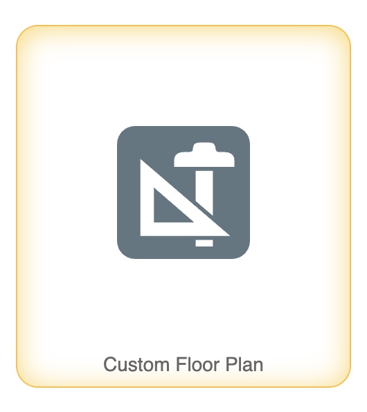
Then I clicked on Custom floor plan to design my very own layout.
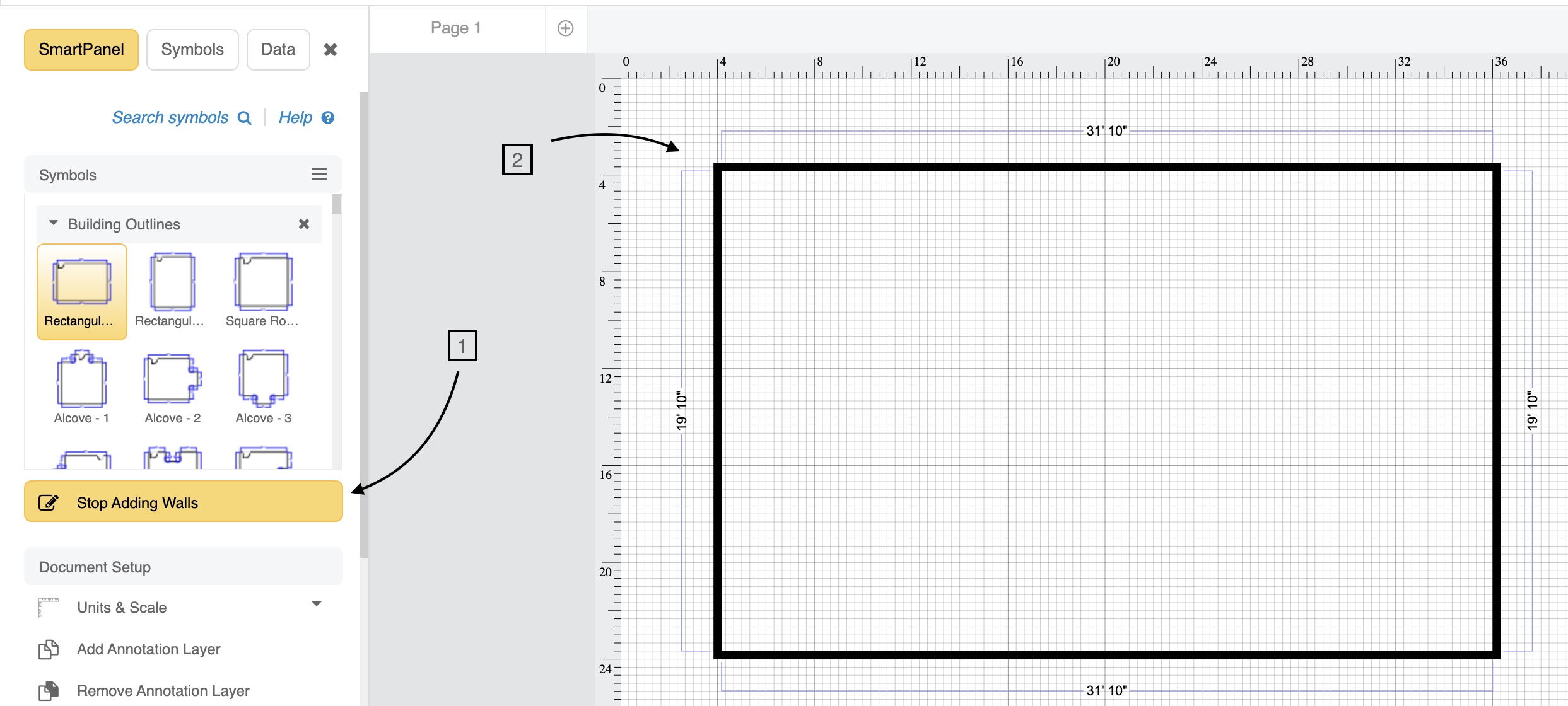
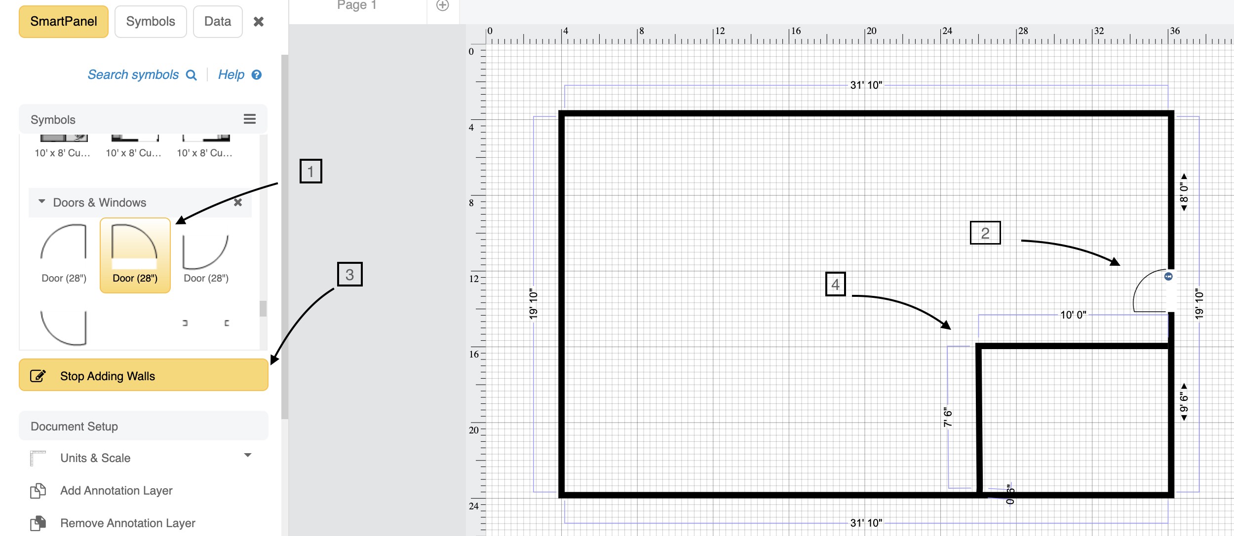
2 - Now I started to begin carrying out my layout by first selecting Add walls and sketching it out over the grid where i buit the main walls first to make a frame.
3 - In this step i began constructing the walls of the bedroom and installing a door, as well as installing a door for the main entrance.
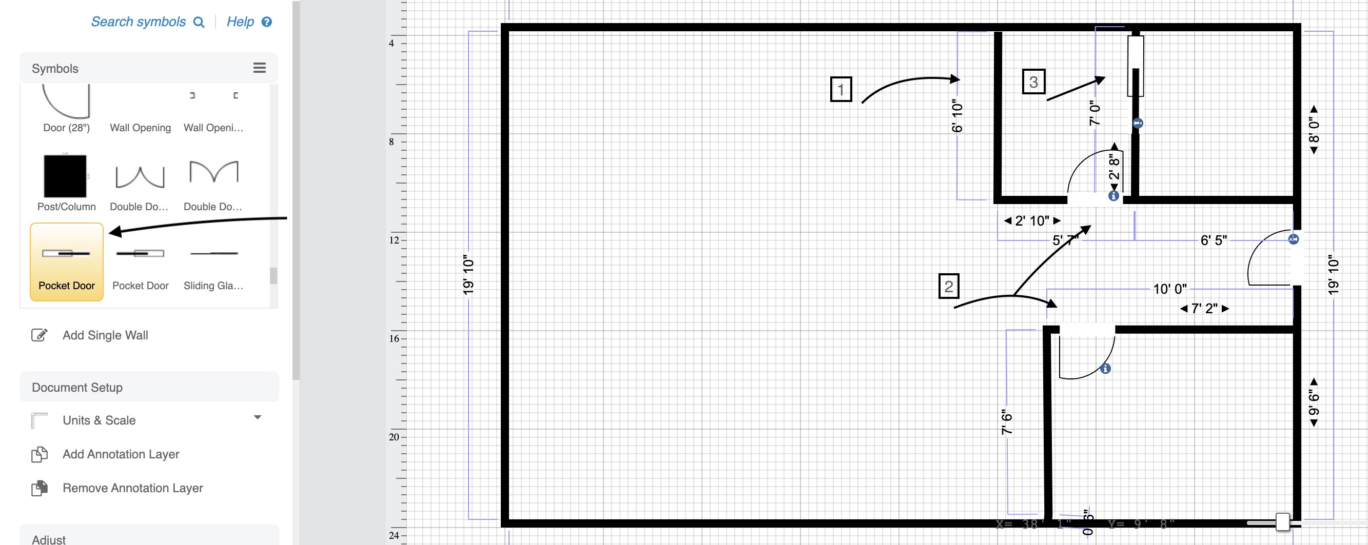
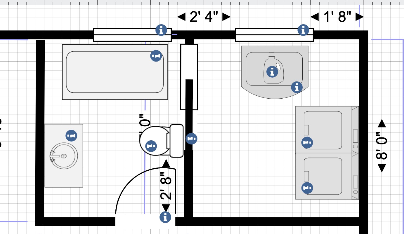
I then built the rest of the rooms, including the bathroom and laundry room, as well as doors and a sliding door for the laundry room within the bathroom.
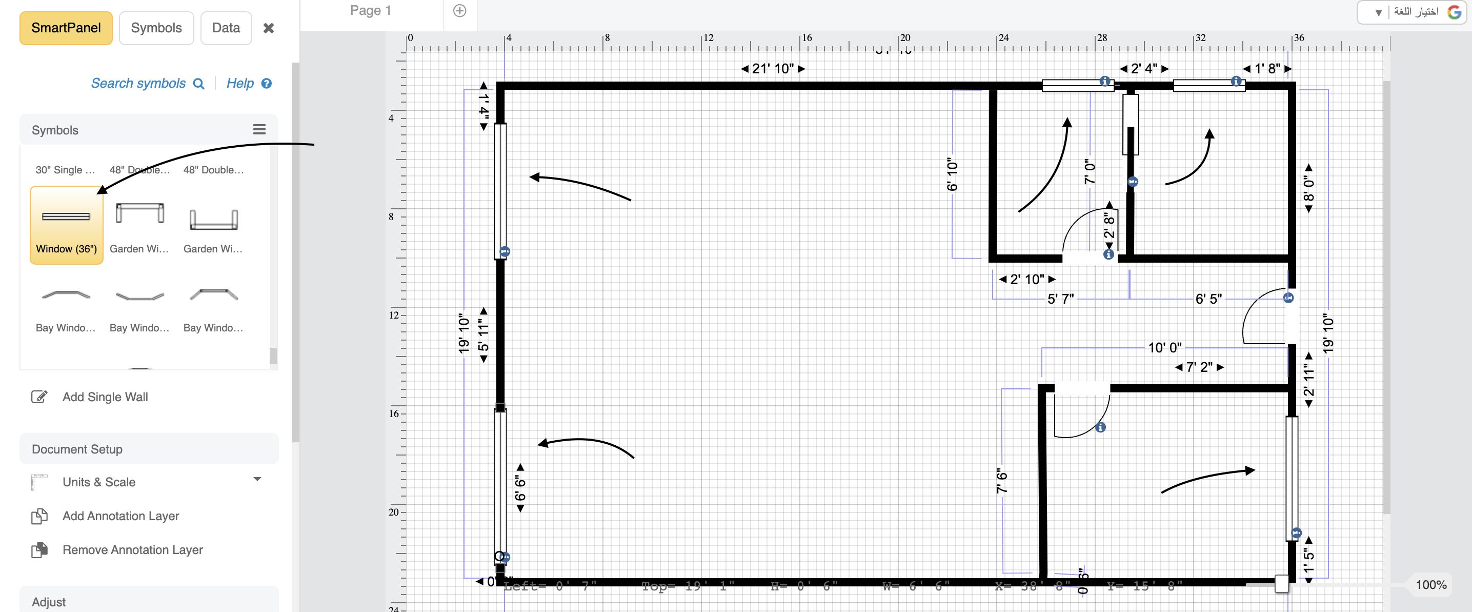
Here I browsed for windows, and added a couple to each and every room.
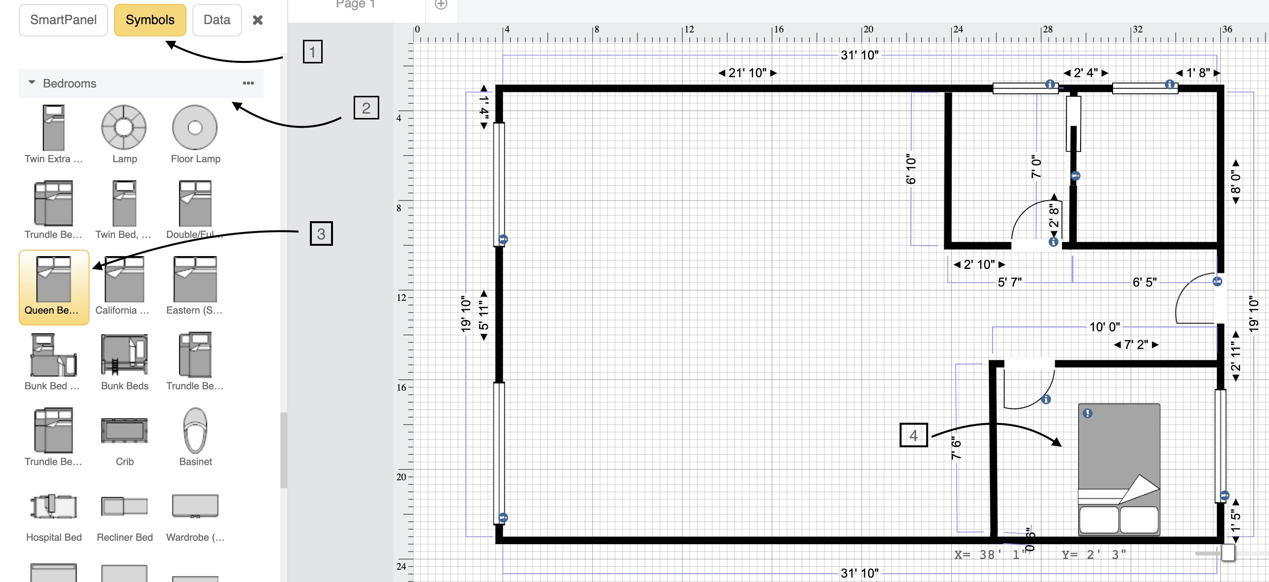
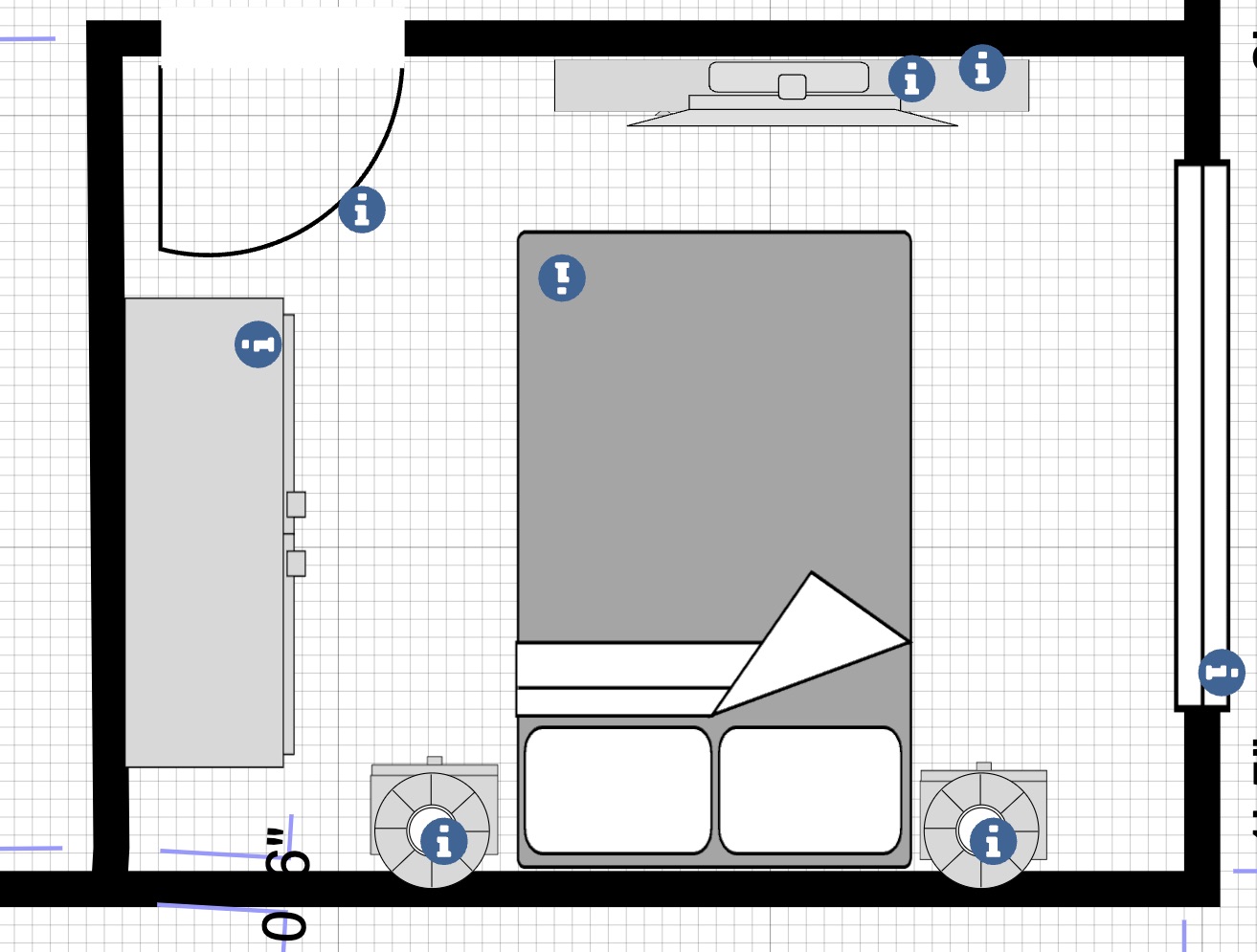
4 - In this step I added furniture to mark where everything goes in the apartment plan. I first starte with the bedroom where i went to the right panel, clicked on Symbols> Search> typed Bedrooms where I chose the bed symbol I wanted and added it to the bedroom.
In this image, I added extra furniture to make it more appealing and to serve as a concept for where everything should go.
Nexr, I moved on to add furniture to the remaining rooms, using the right panel and the search engine to identify the specific furniture I required for each room.
Moving on tot he rest of the apartment, I added a kitchen, a dining table, and a living area to complete the layout, as wellas a balcony (where you can see in the final results).
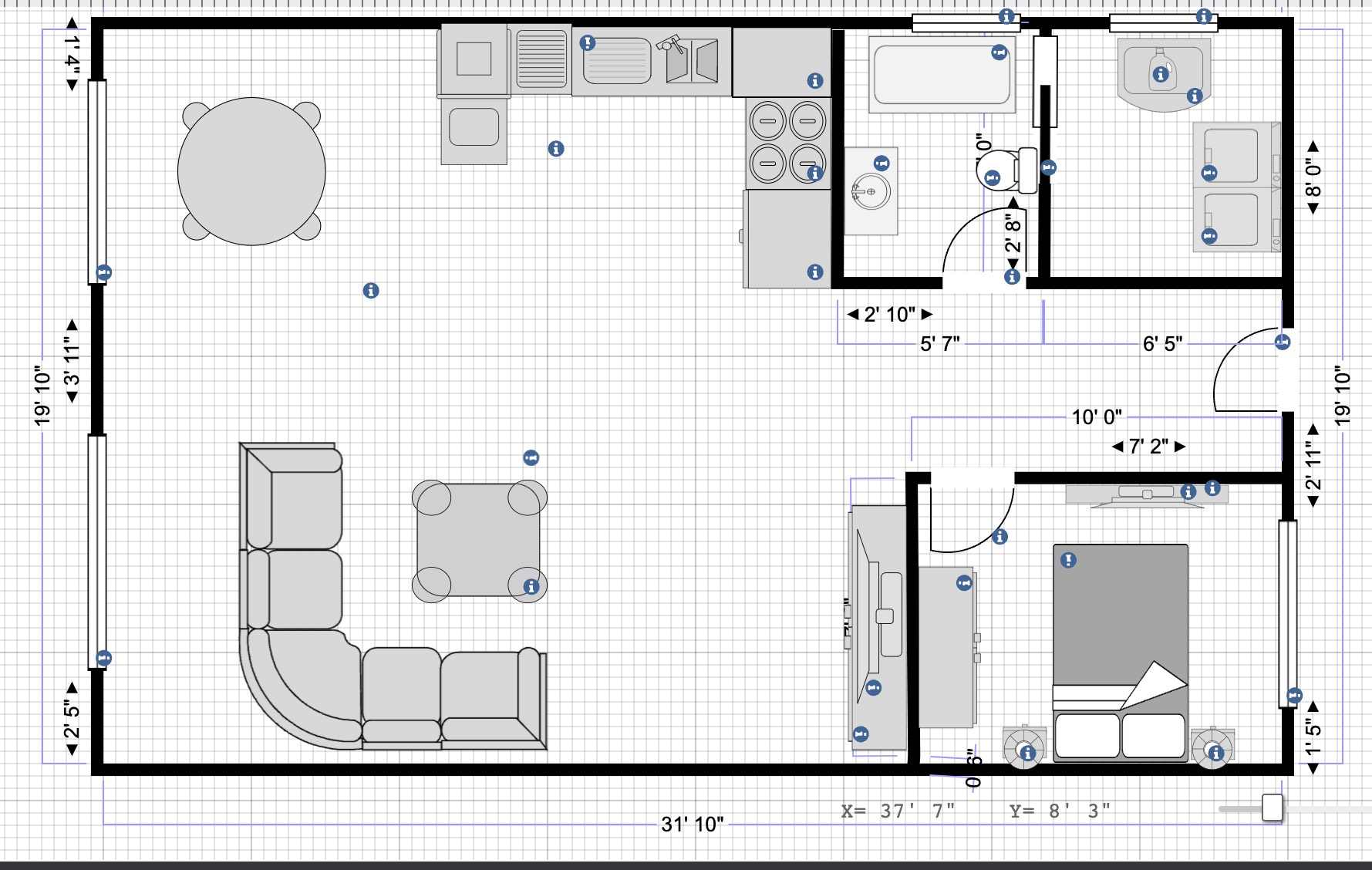
Final Results
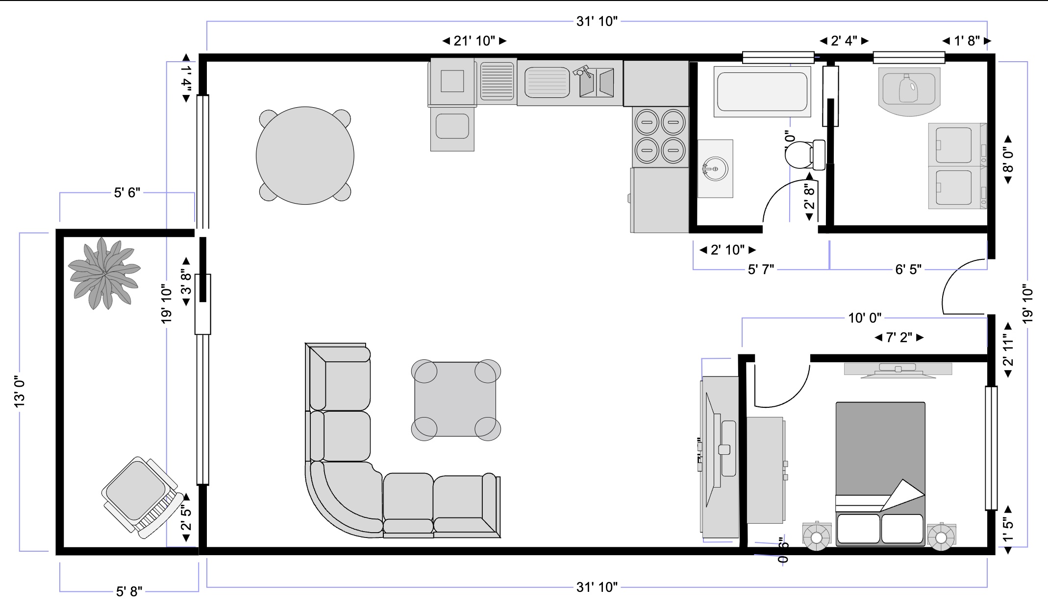
Click here to download the file.
3D
3D software is a form of computer graphics software that allows for the creation, design, and development of 3D images and animations. Users can use 3D software to see, develop, and manipulate an item, environment, or any graphical element in three dimensions.
Fusion360
Fusion 360 is a product design and production cloud-based 3D modeling, CAD, CAM, CAE, and PCB software platform. Design and engineer items that are pleasing to the eye, have good shape, fit, and function.
I downloaded fusion 360 using an educational license from Autodesk for free.
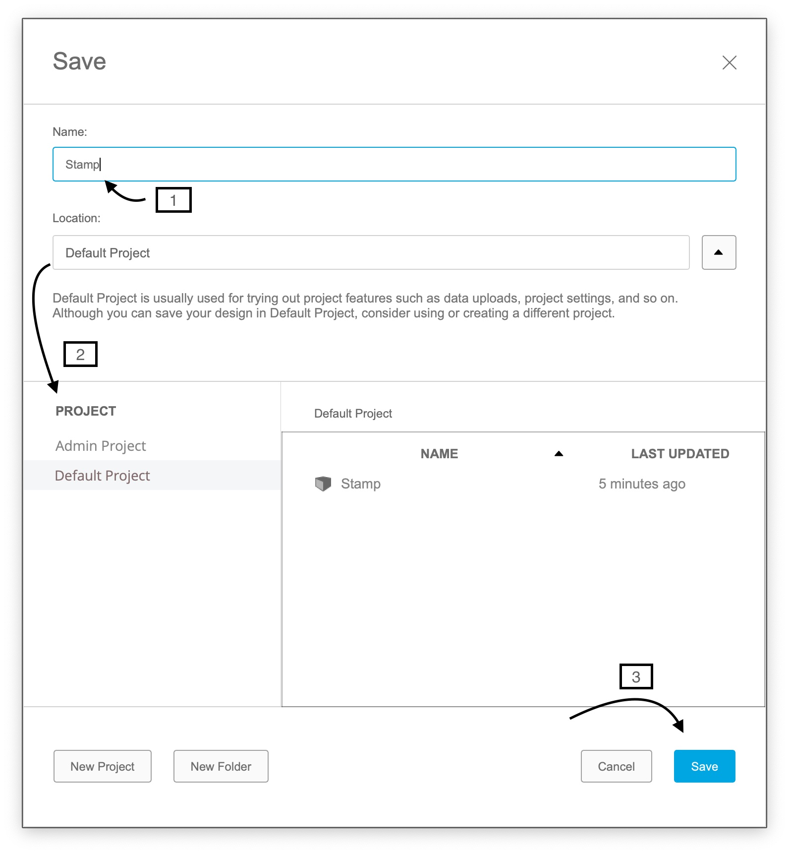
First I began off by watching a Youtube Tutorial to start working on my first CAD project and familiarize myself with the program. I proceeded by saving my project to begin the designing process.
Designing a Stamp using Fusion360
First I began off by watching a Youtube Tutorial to start working on my first CAD project and familiarize myself with the program. I proceeded by saving my project to begin the designing process which is designing a stamp.
The stamp plate
2D
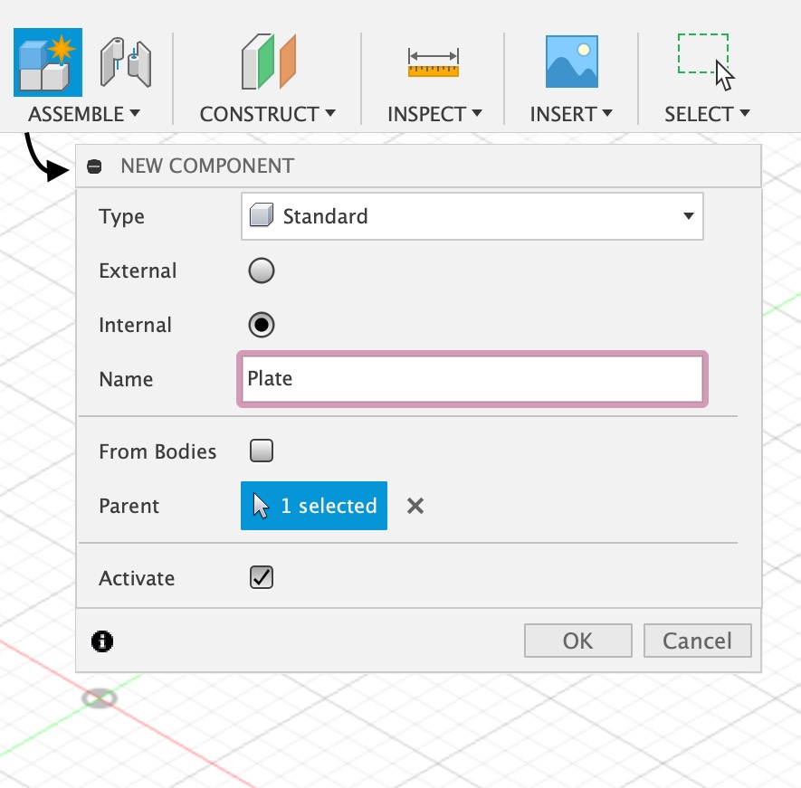
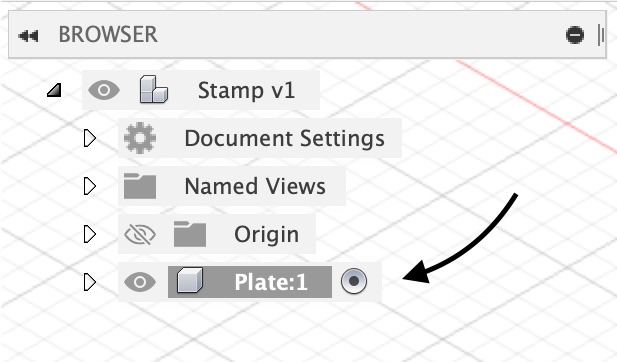
1 - I continued by assembling the first component after saving my project and ensuring that I could access it in my browser.
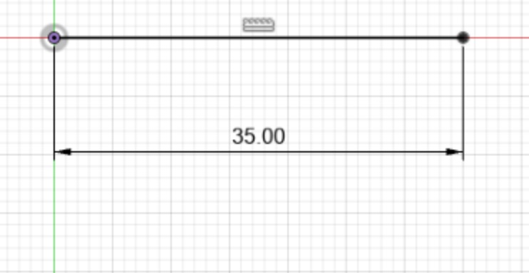
2 - Next, I started sketching using the keyboard shortcut “L” and picked a front perspective to sketch in 2D initially.

I then started dragging my cursor across the screen to sketch a line, and typing in the exact measurement i want.
Accordingly, I started adding lines at an angle with a specific degree, at each end of the first line.
(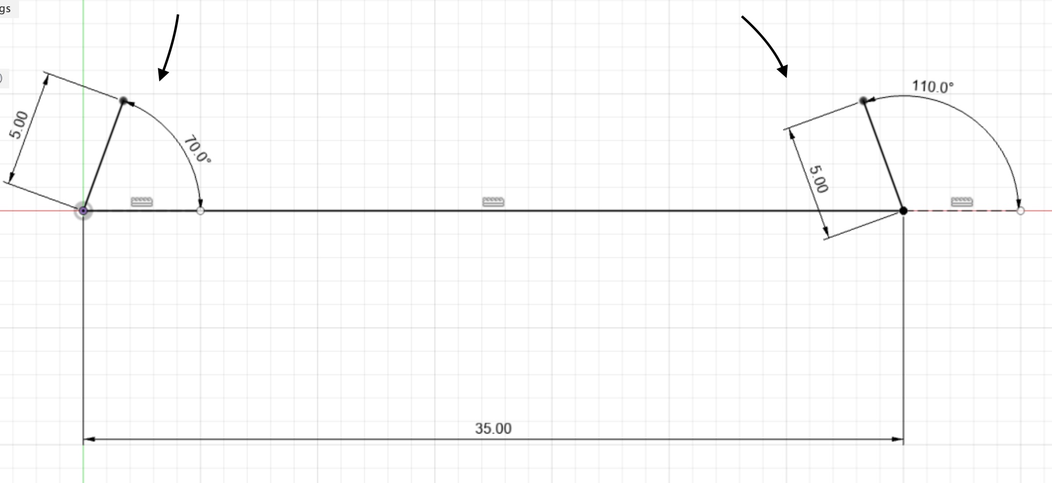
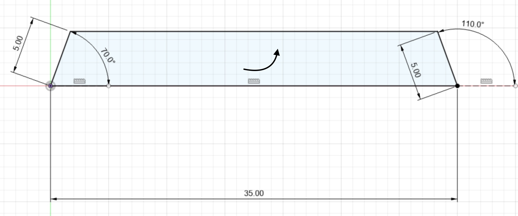
I then connected both tilting lines to create a 2D shape.
3D
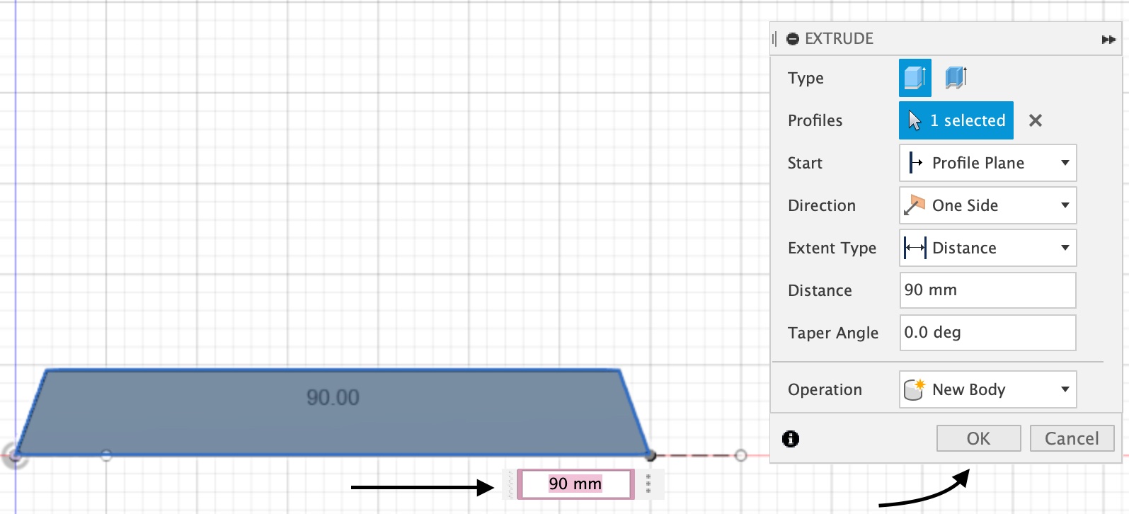
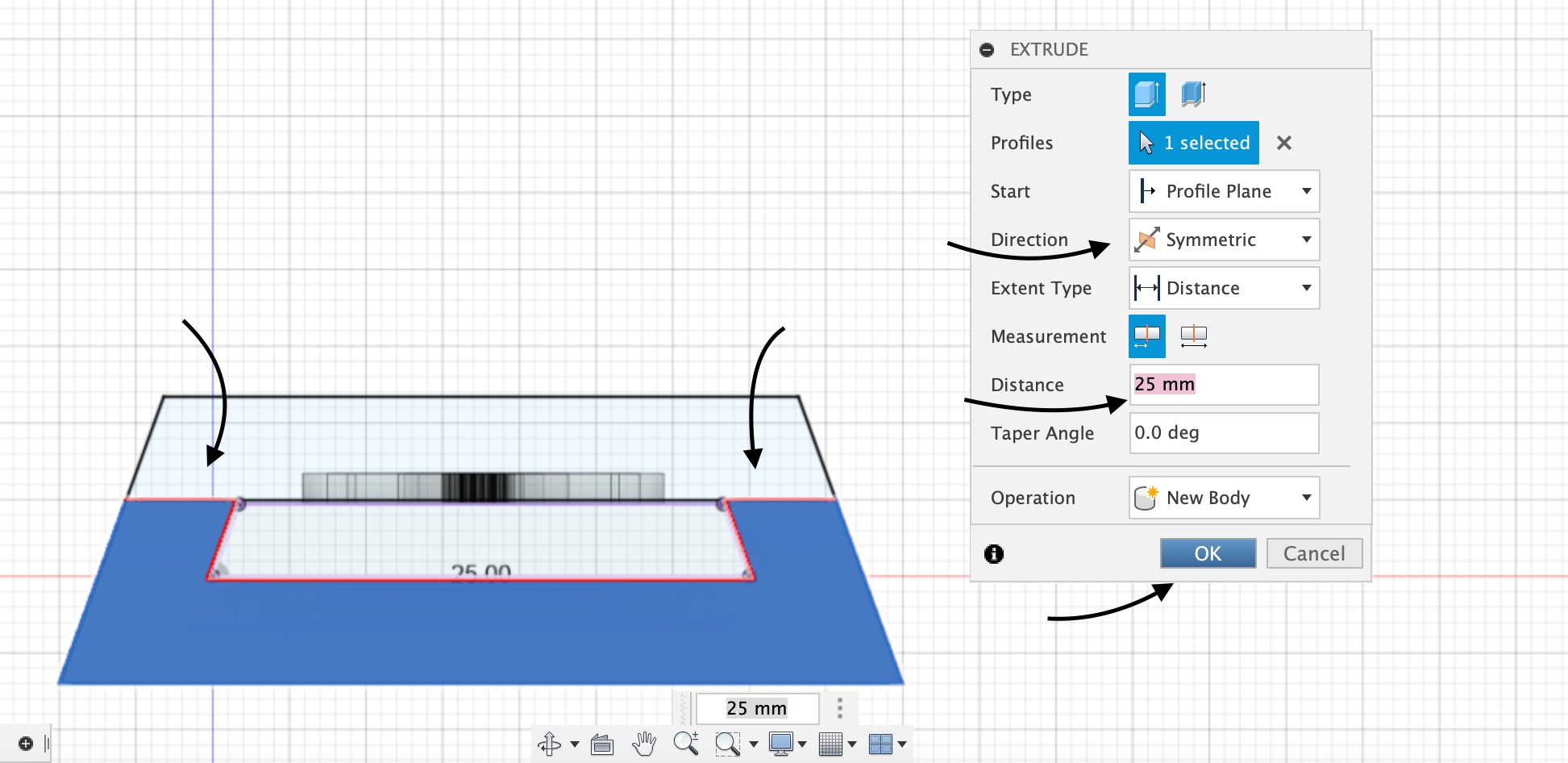
1 - Thereafter, I needed to convert the 2D shape to a 3D shape, therefore I selected the shape, I went to Create and looked through the drop-down options, and then chose the Extrude option in order to add thickness and depth to the shape selected.
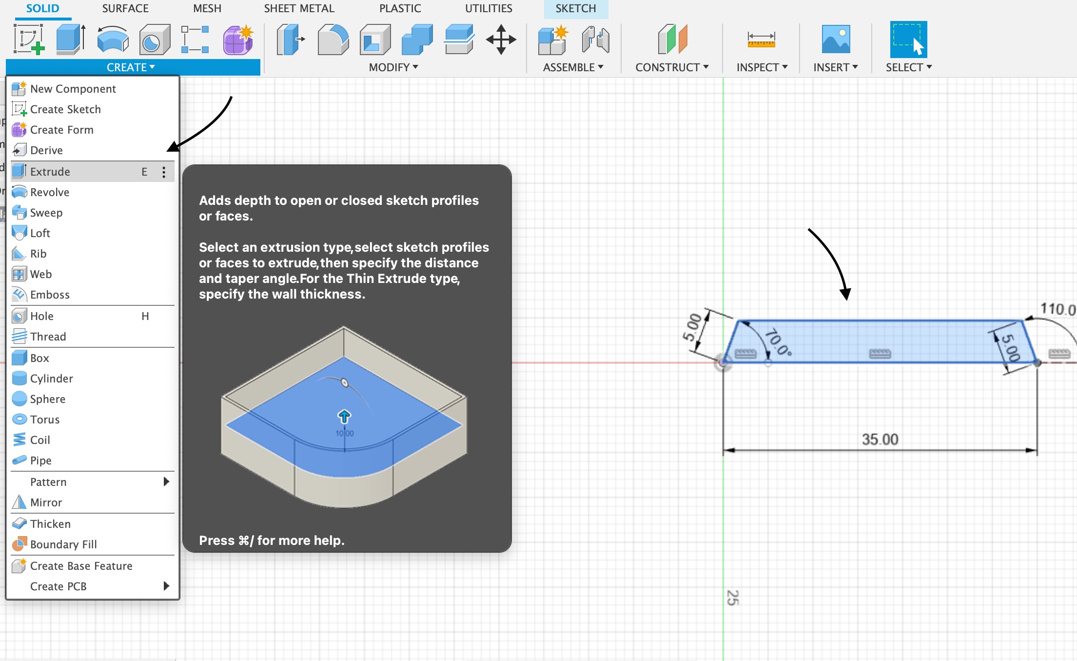
I entered in the ideal shape’s size and hit ok.
I altered the screen perspective to get a 3D view of what I made.
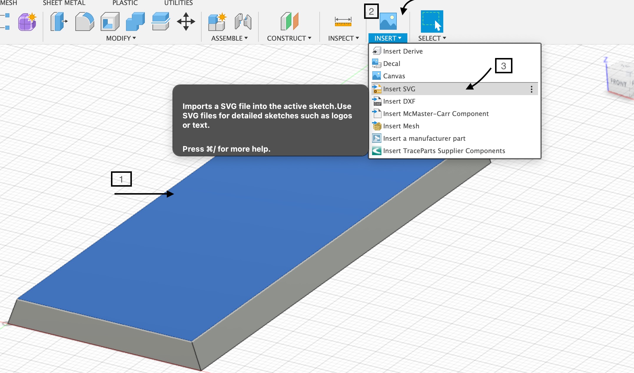
2 - It was time to add the stamp logo, I selected the front face of the stamp, then I clciked through Insert>Insert SVG to choose the stamp logo, and that could only be added using an svg file, which i downloaded form this website.
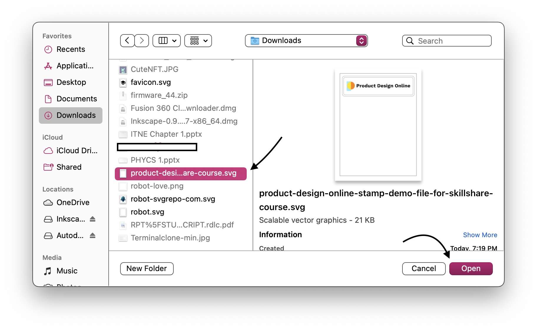
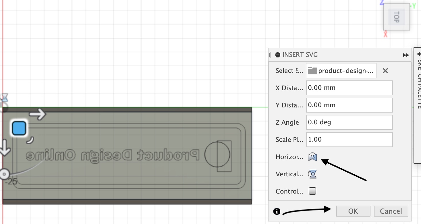
I positioned the stamp logo exactly where it should be, following that by clicking on ok.

I also had to do a critical step, which was to horizontally flip the logo to ensure that it was in the proper alignment.
Following on, I needed to give the stamp logo depth so that it could be utilized as a functioning stamp. So I selected letters and shapes that I wanted to add depth to after clicking on the “E” command for Extrude and typed in the depth I wanted for the stamp.
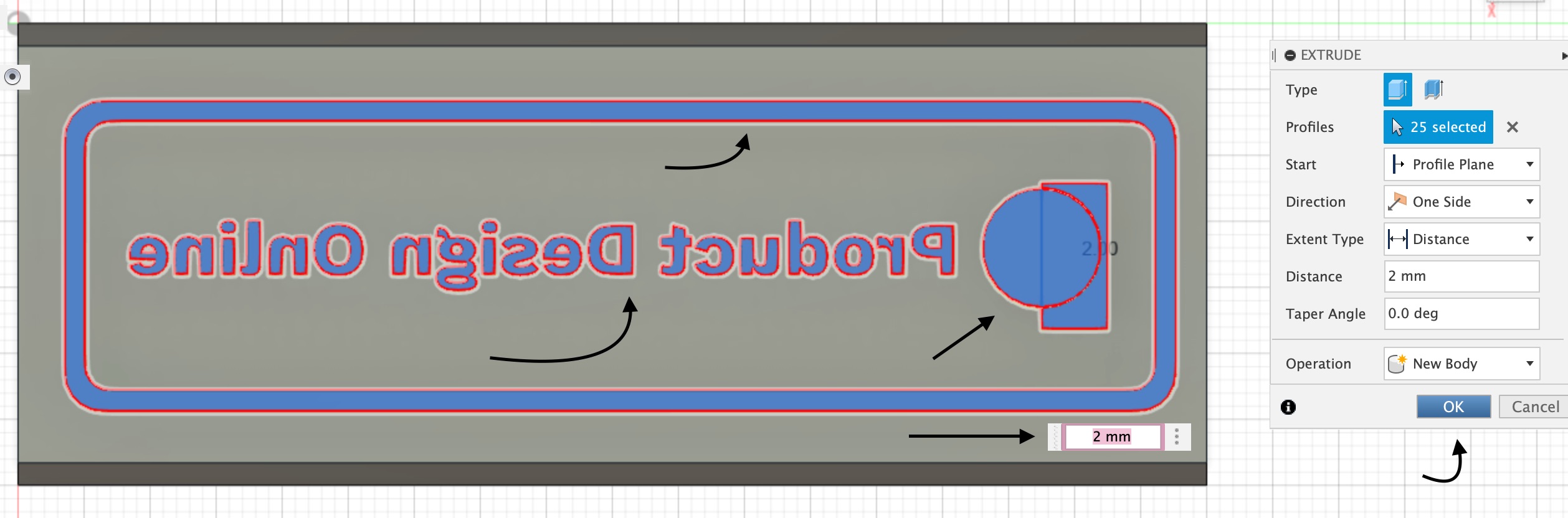
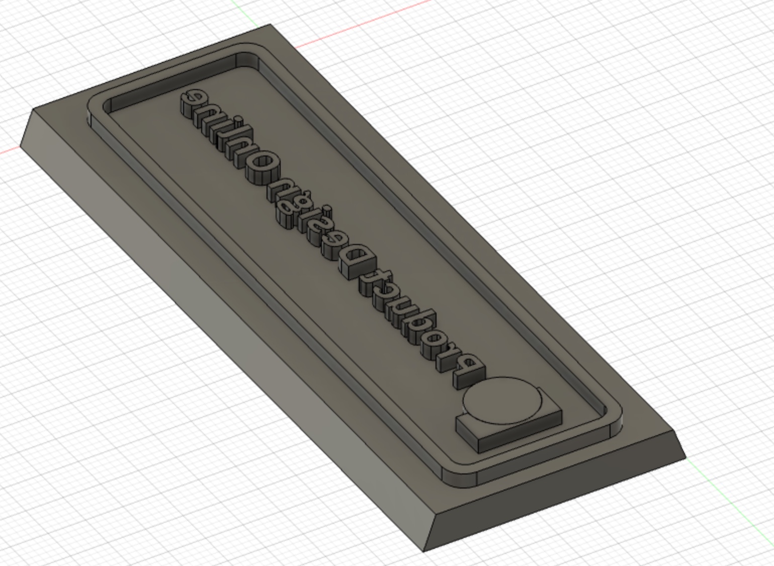
Looking at it from a different point of view, I can see that the design operation was completed successfully, and the stamp logo was given depth, make it 3D.
The stamp handle
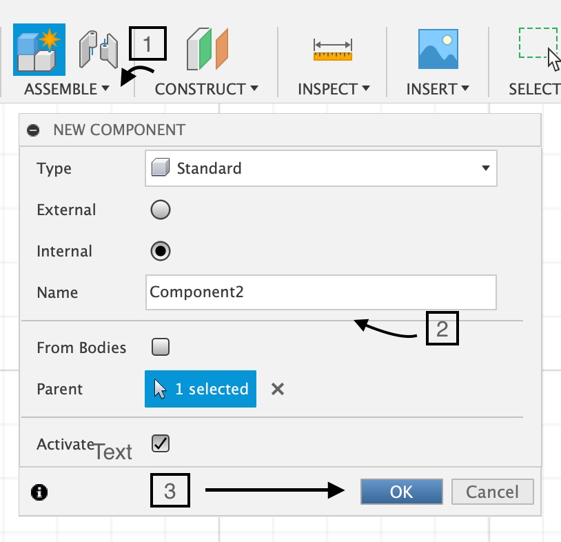
1 - It is essential that each part of the stamp should be designed and executed separately, so when I was designing the handle, I once again came back to and clicked on Assemble > New Component , I then named the new component and clicked ok.
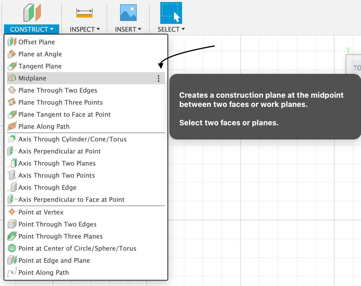
2 - Afterwards I headed to Construct> drop down menu> midplane. This enables me to join the second components in the center of the main component.
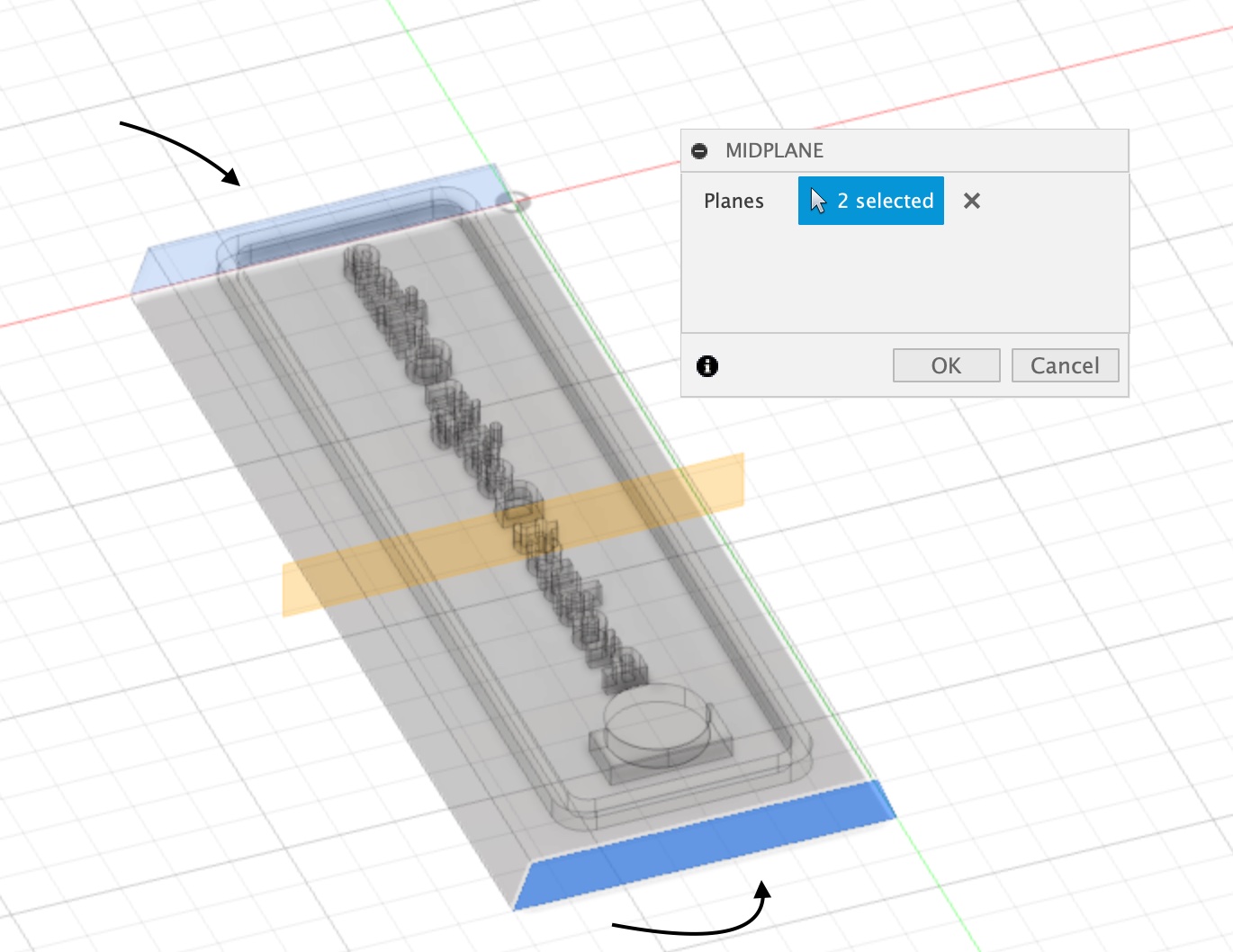
I then picked both ends of the first component, the stamp plane, and an imaginary line (the one in orange) was drawn to give a preview as where the other component will attach to it.
After that, I typed the command “P” for project and clicked on the midplane line and selected its outline.
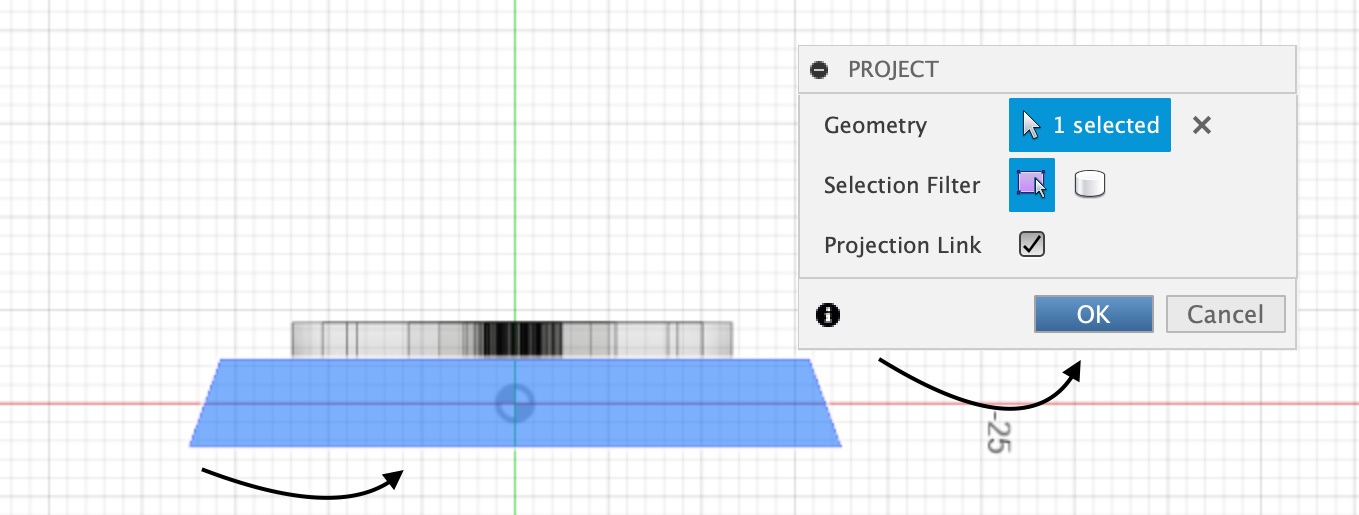
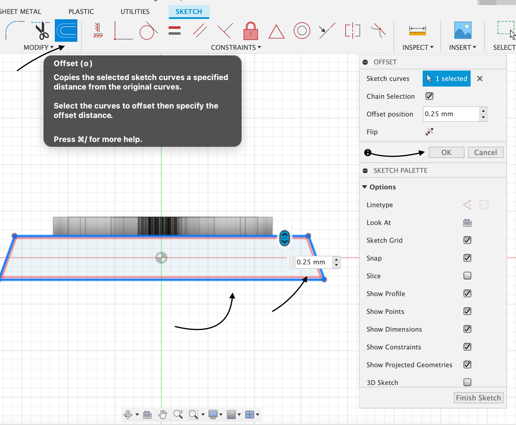
I utilized the offset option to make the handle’s foundation, selecting the midplane for the handle’s creation, then typing in the measurements and clicking ok.
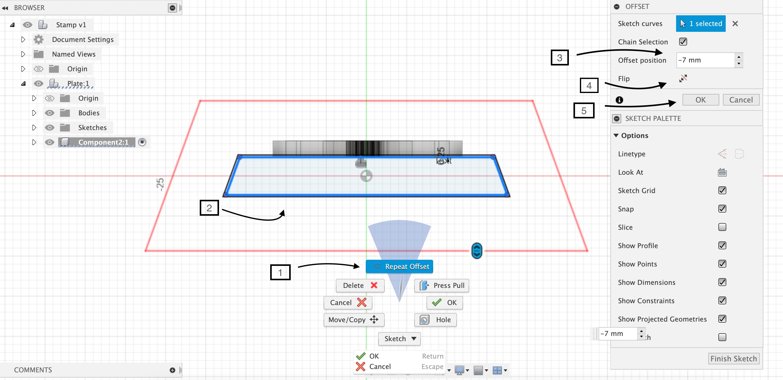
In order to increase the thickness of the handle base, ill select the original sketch > Right clcik> repeat offset> type in my measurement> flip to ensure it holds on to the stamp> ok.
To make a functioning stamp, I simply needed to leave a foundation for the handle and cut the top section off, so I drew two lines on each side and lengthened the handle to make it fit on the stamp.
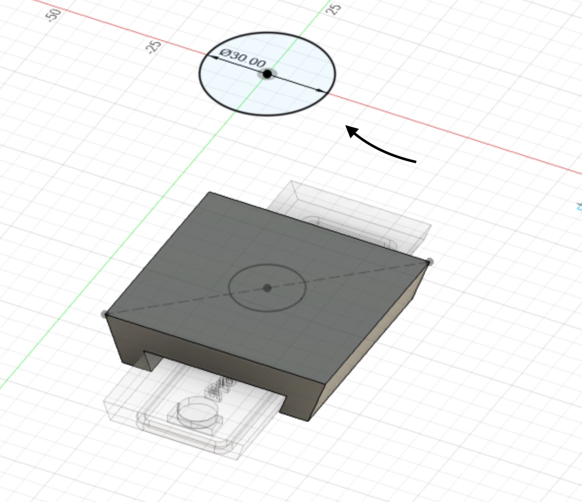
3 - In the bottom view of the habdles’s base, I created a construction line as well as construction circle that acts as where the handle attach, in the bottom perspective to assist me draw, as seen in the image.
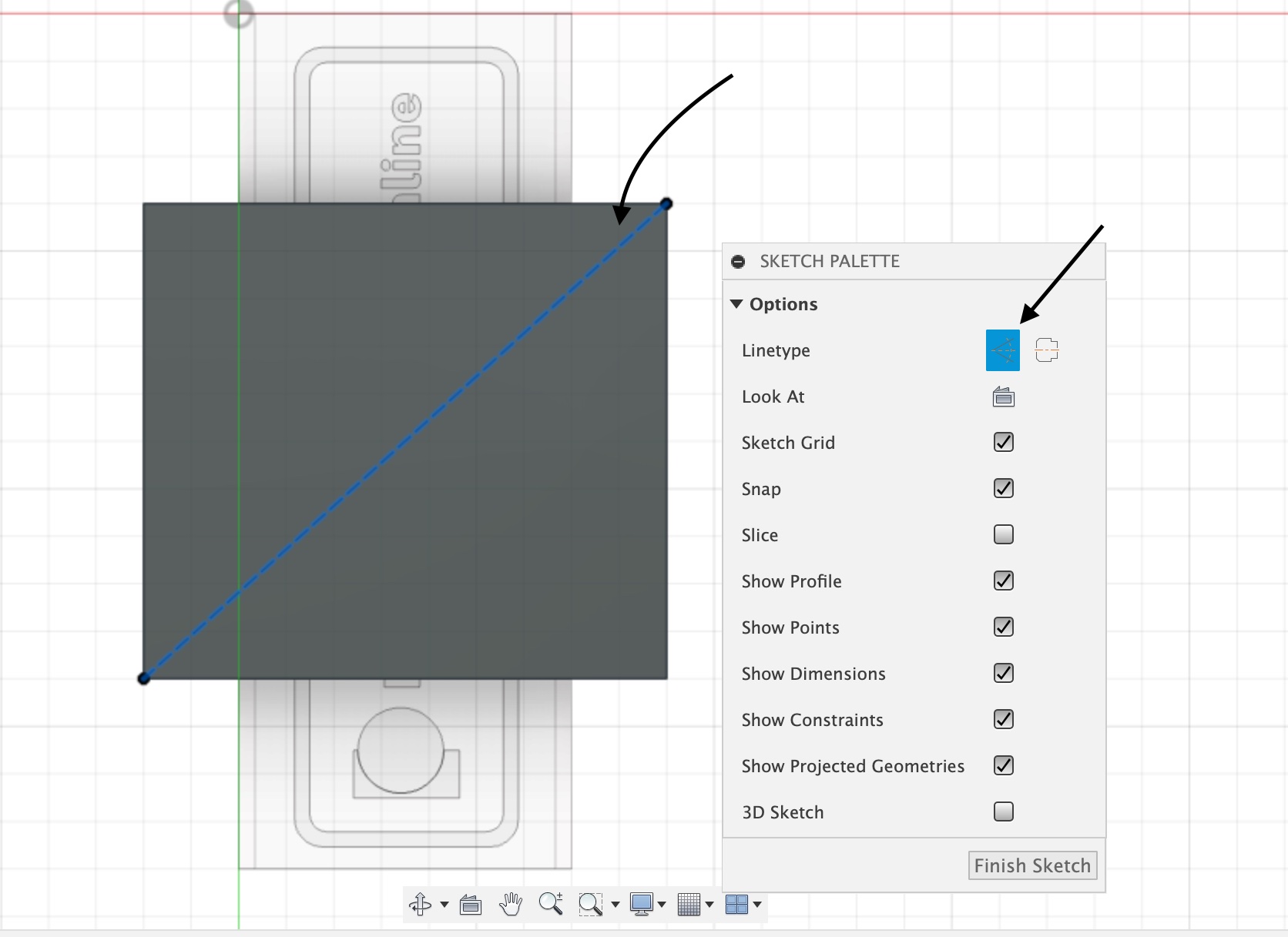
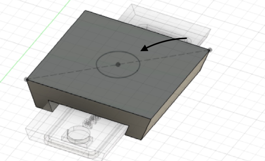
Because I can’t draw in empty space in Fusion, I’ll have to use the contruct> offset plane option to complete the sketch I wish to do.
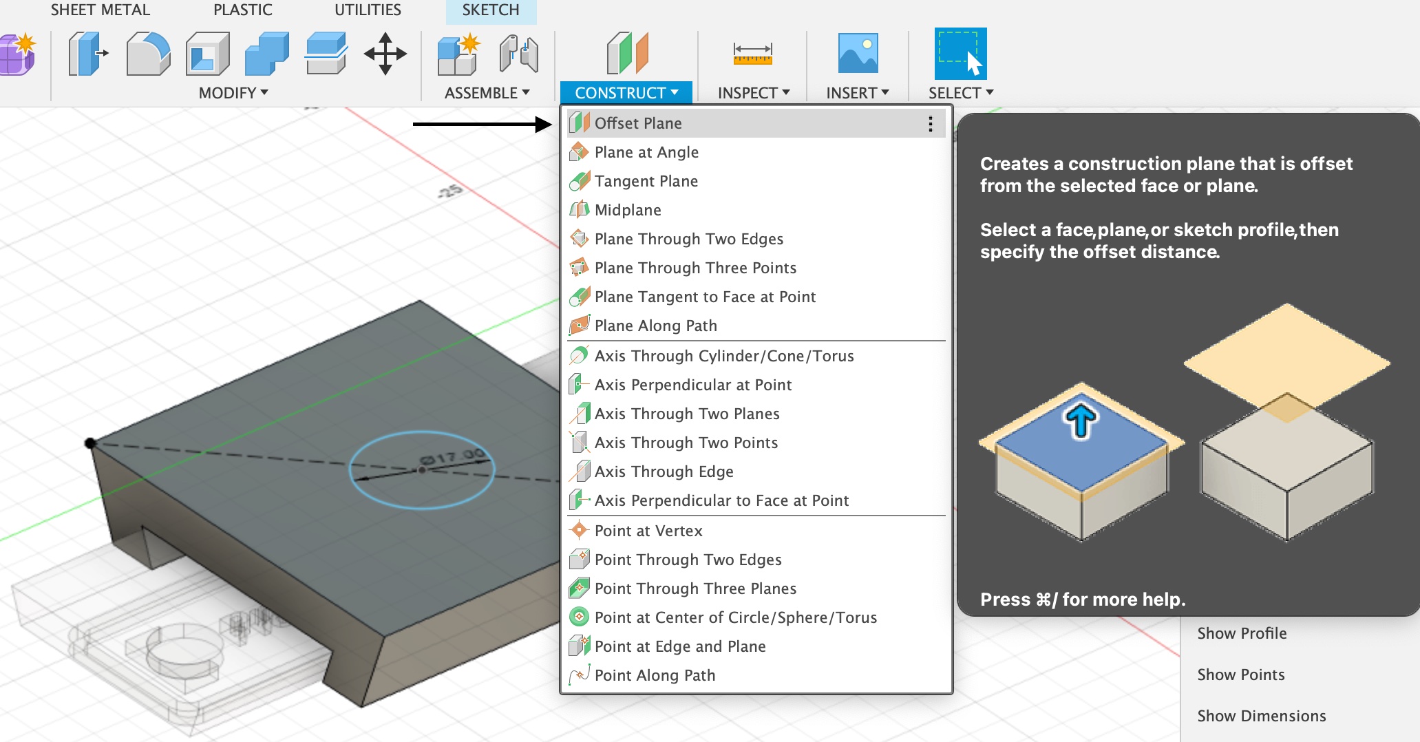
After creating an offset plane, I clciked on it to begin sketching.
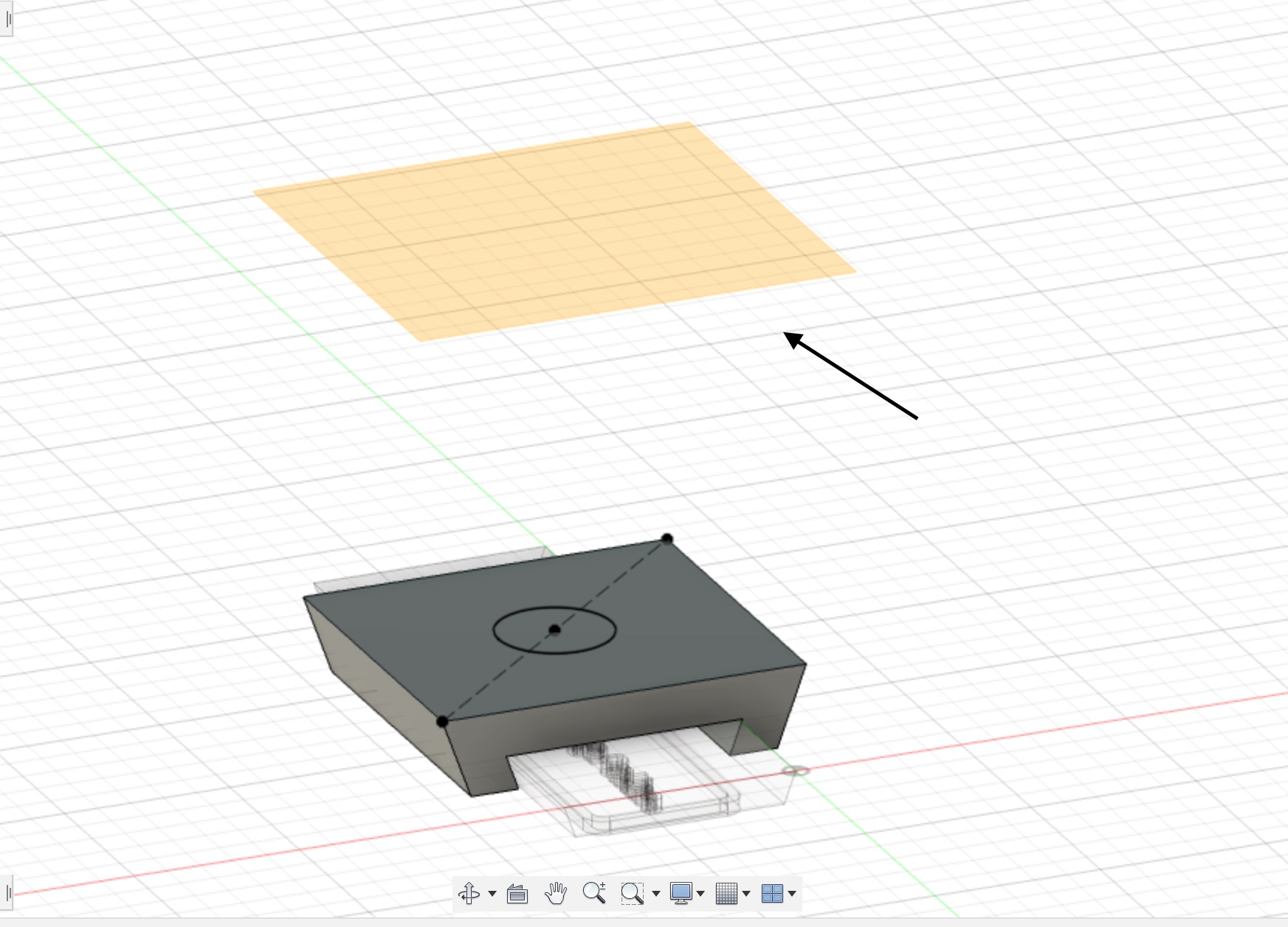
I sketched a circle with a larger diameter for the another end of the handle.
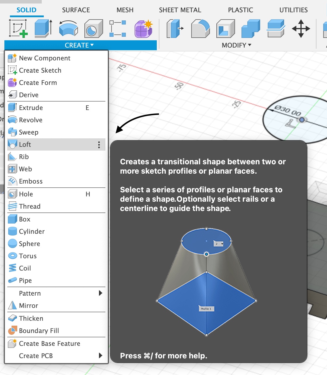
Then I went to Solid tab> Loft> choose the base circle> choose the circle place on the offset plane> ok, and an initial handle was made.
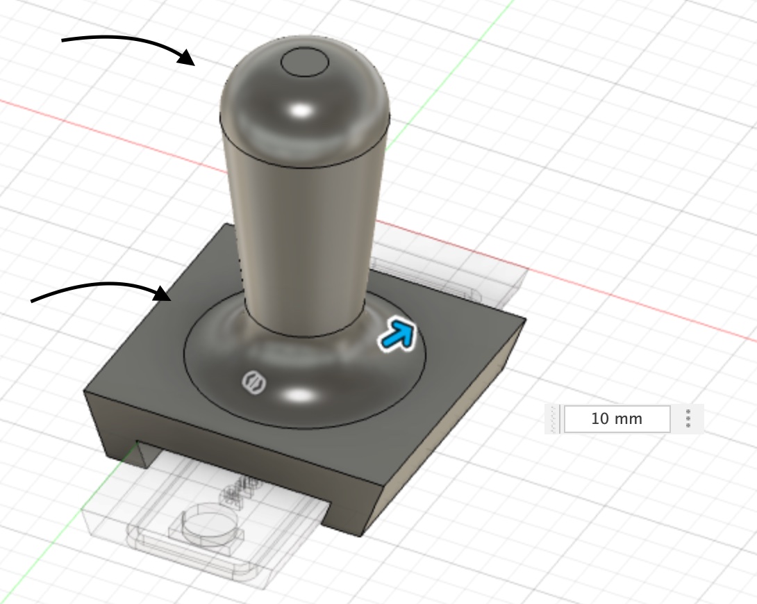
4 - When it came to modifying the corners of the handle, I typed the commant “F” for Fillet to curve down the corners, to make it look more appealing, as you see in the image.
Final Results
Click here to download the file.
TinkerCAD
Tinkercad is a free online 3D modeling tool that can be used through a web browser. It has been a popular tool for making models for 3D printing since its release in 2011.
I started by watching a YouTube tutorial on how to recreate a design of the Leaning Tower of Pisa, and then I set up an account on Tinkercad to be able to use it and begin my project.
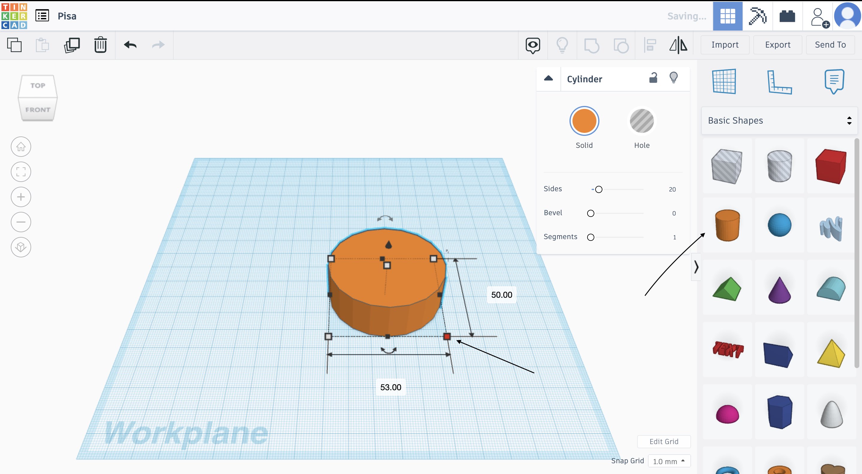
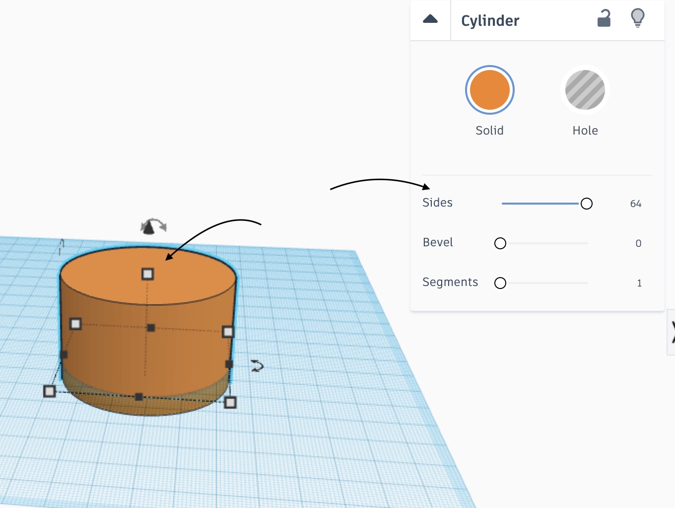
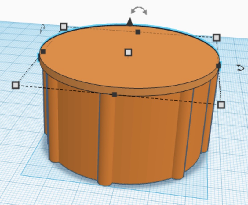
1 - I first selected the cylinder shape from the right panel and sketched it on my working space.
To smooth out the sides I selected the shape and moved to the drop down menu and increased Sides to the maximum.
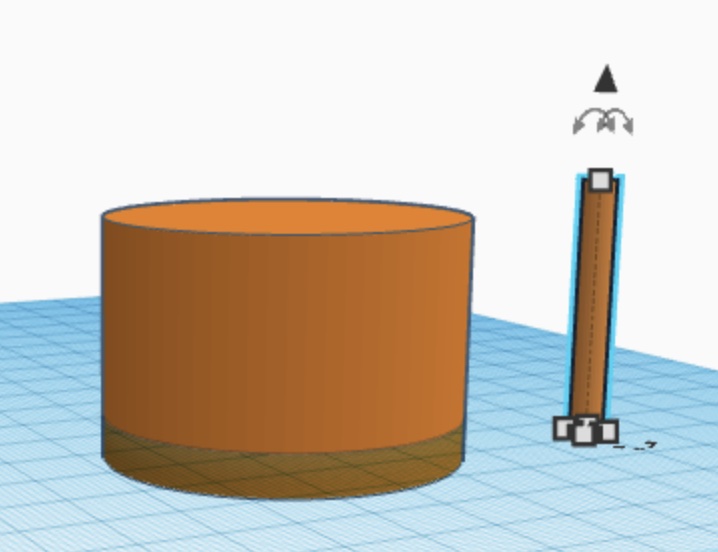
I then skecthed another cylinder on my working space but a much slimmer and smaller version of the first one, and moved it so it collides with the bigger cylinder.
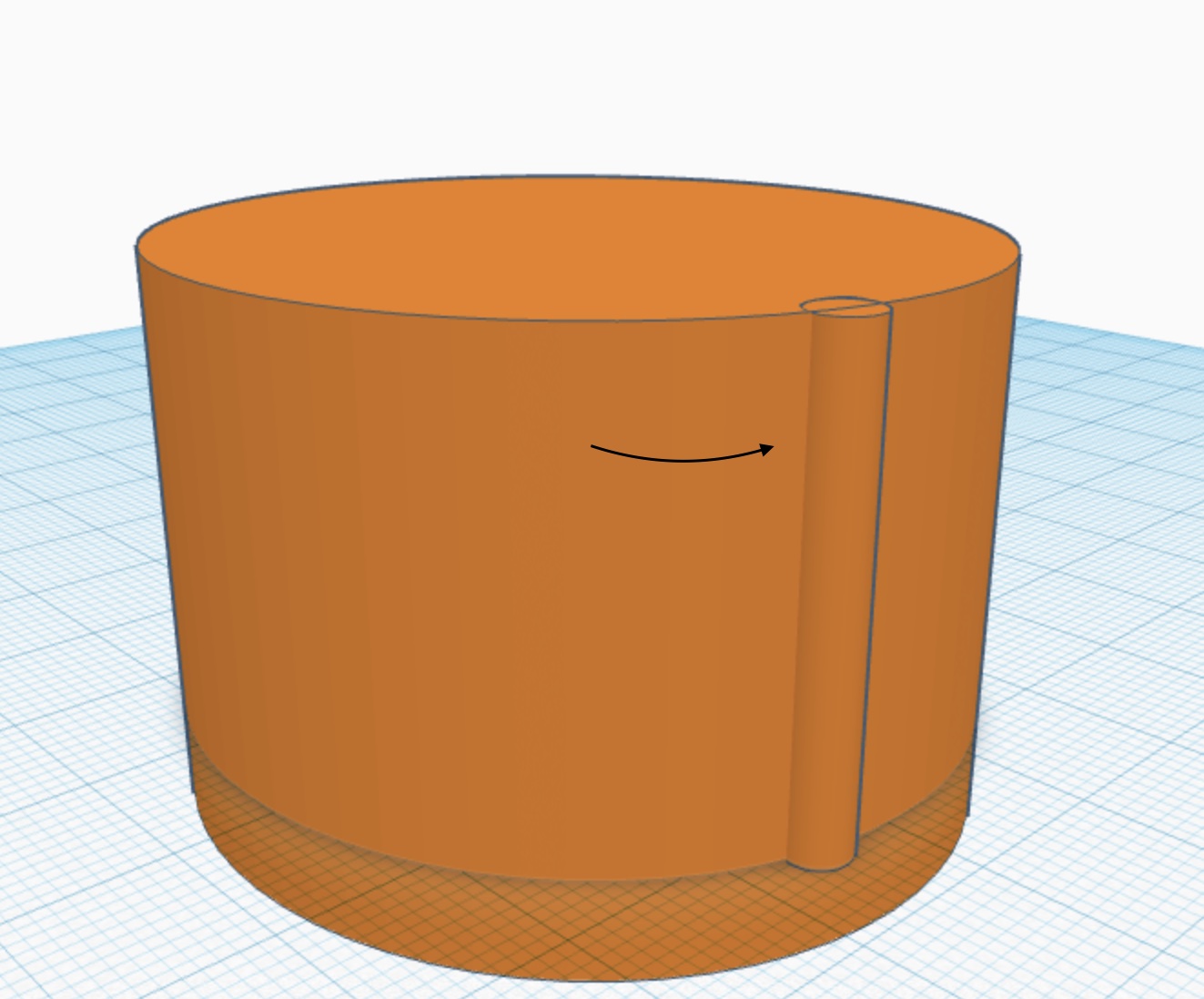
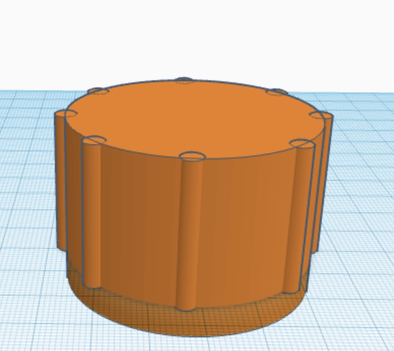
I then duplicated the slim cylinder which in this case acts as a pole so I can add it surrounding the main cylinder as in the image below.
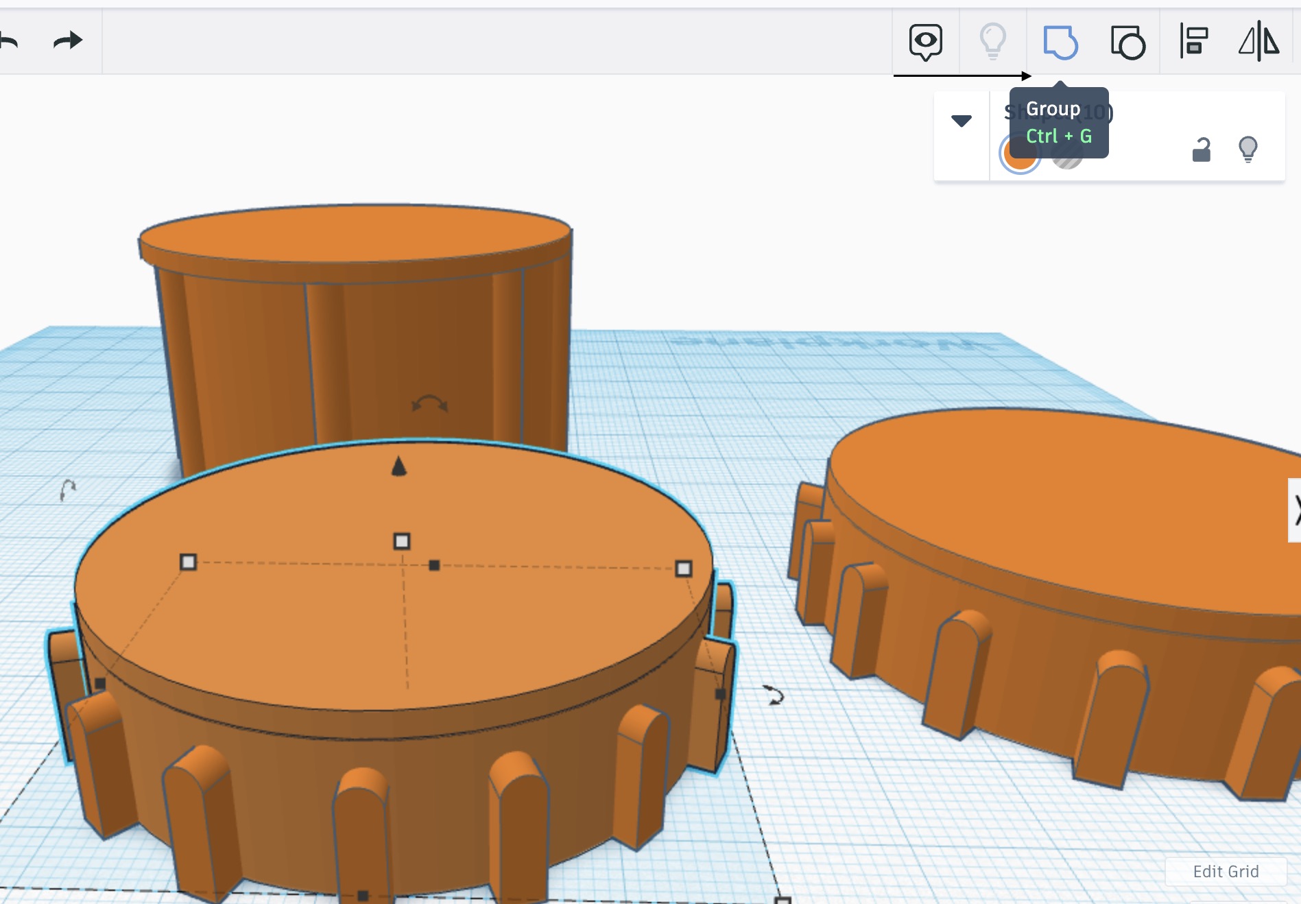
To create base for the next cylinder which is going on top, I duplicated the main cylinder, and decreased its height, and increased its width as in the image below.
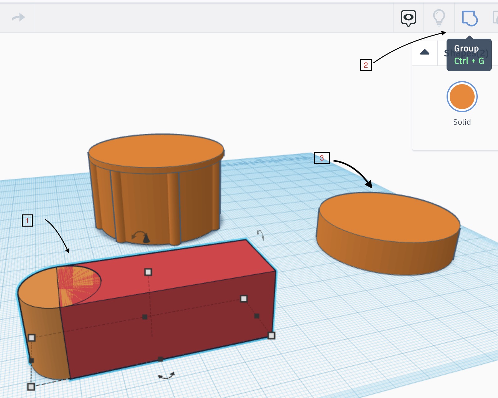
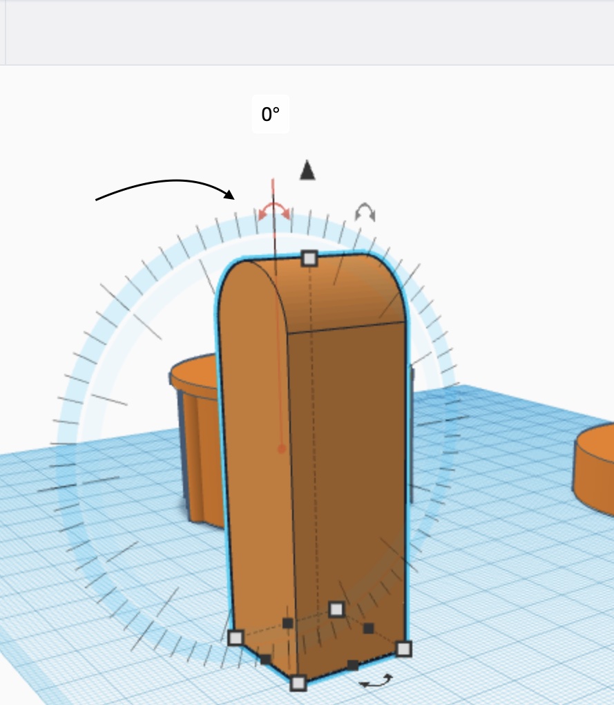
2 - To design the windows i sketched a cylinder with a rectangle that cuts the cylinder halfway through, as of then I selected both of the shapes, grouped them, and rotated it so it stands on a right angle. After that, i sketched a bigger cylinder which acts as a floor for the main tower.
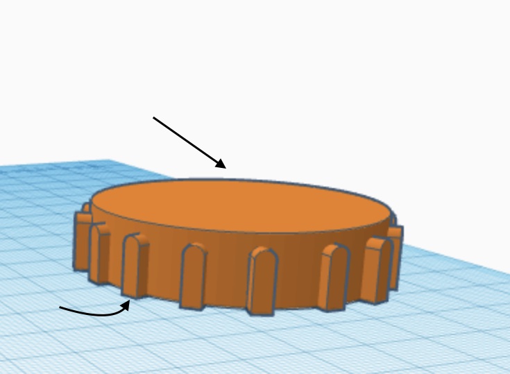
Moreover, I decrease the size of the windows I designed, duplicated them, and positioned them around the bigger cylinder. I duplicated then that cylinder and grouped it.
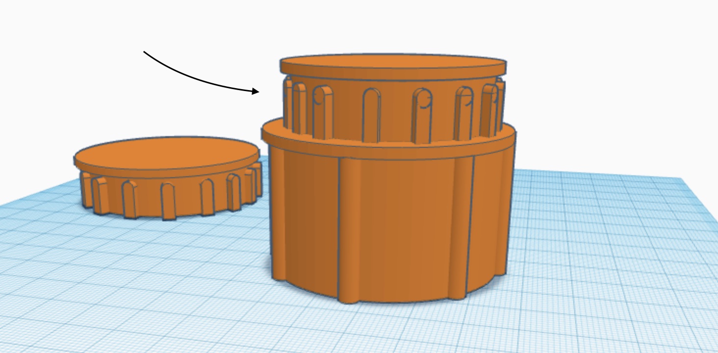
3 - Building the actual tower, all i had to do was duplicate the cylinder I just grouped about 5 times and elevate it upwards, stacking them on top of each other.
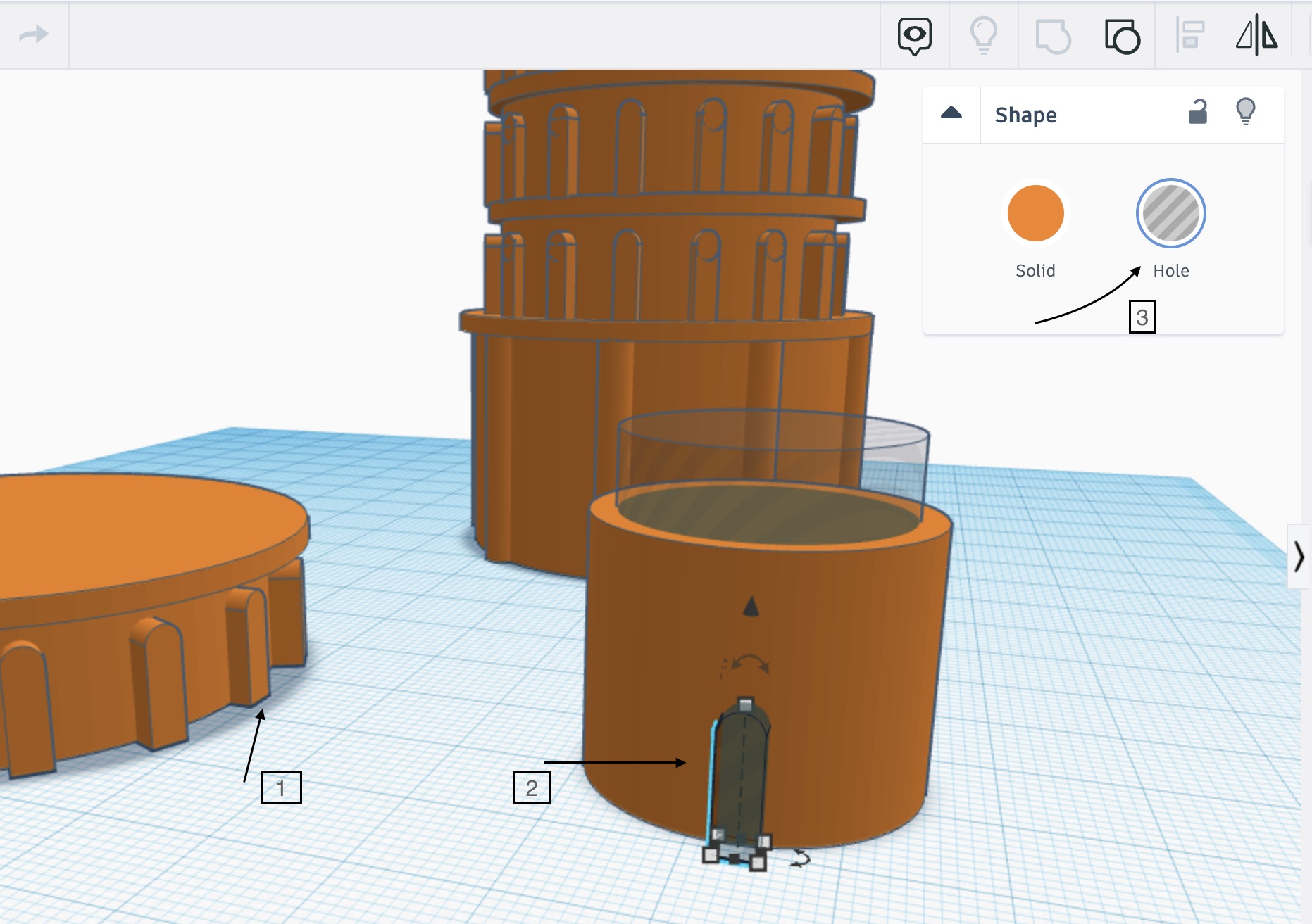
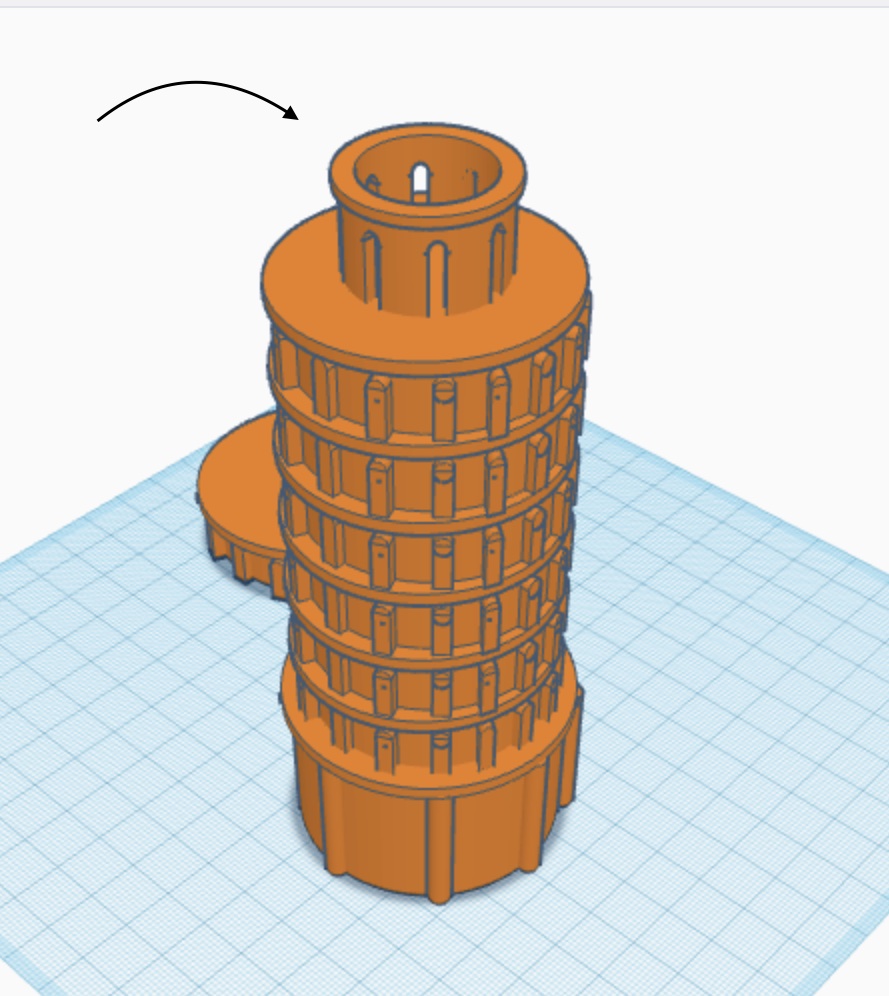
For the dome of the tower I sketched a new cylinder, and moved the initial windows i created, increase their height, and added them around it. Next i duplicated the cylinder, modified it into a smaller version, and chose the hole option for both the windows and the cylinder, to make them hollow from the inside.
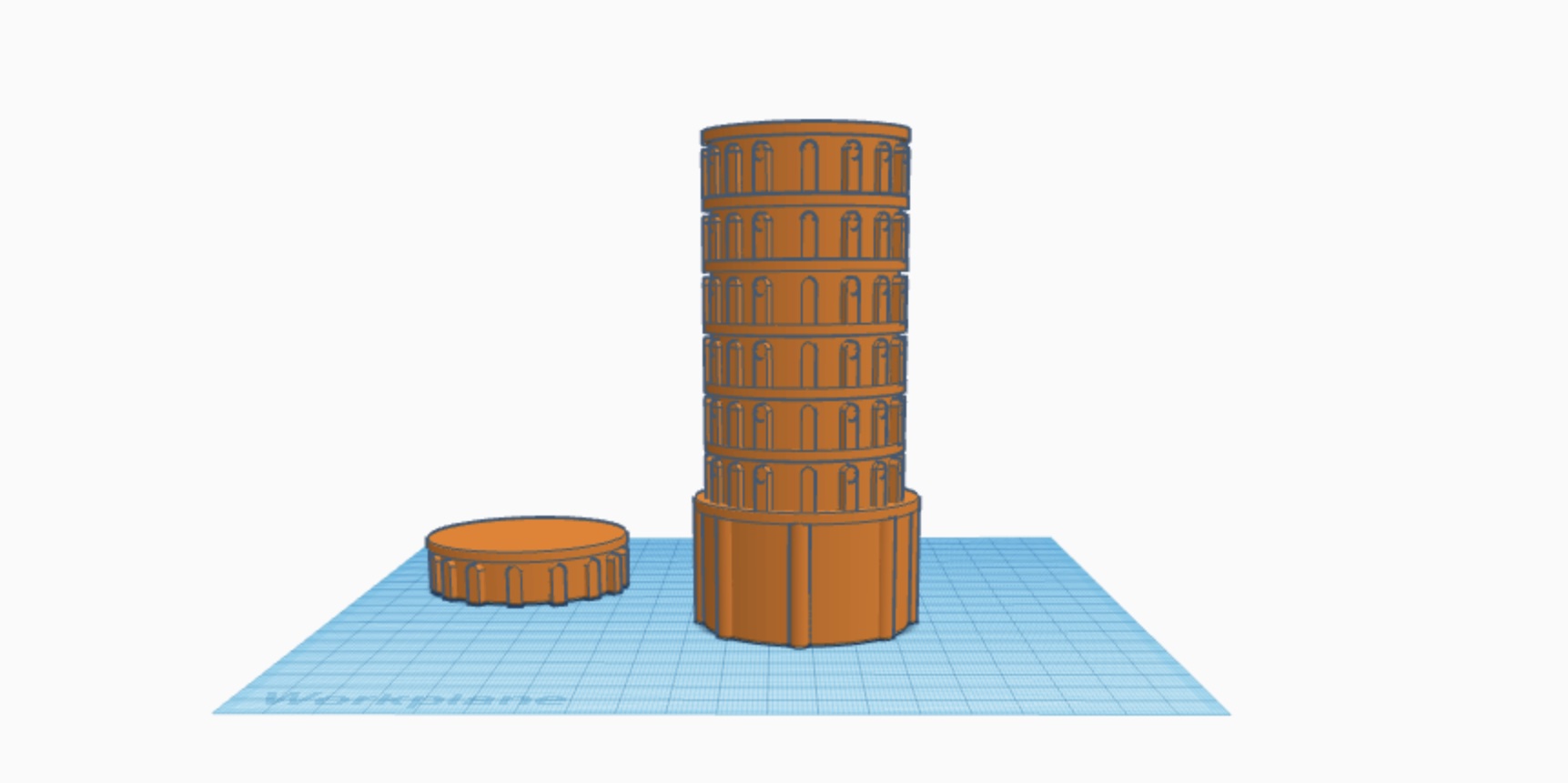
Thereafter,I selected the whole that I’ve just created and I grouped them all together and took it on top of the tower.
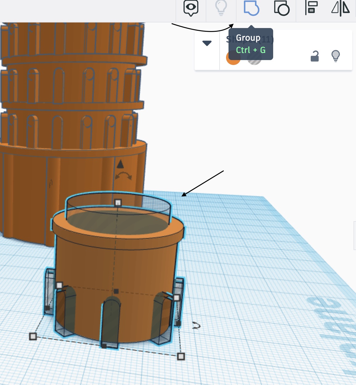
Next, I sketched a cylinder that acts as the base of the tower, as in the image below.
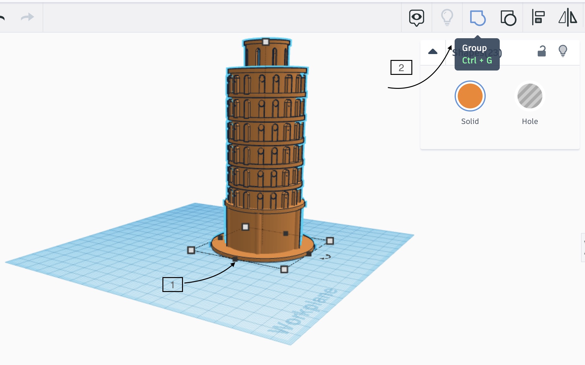
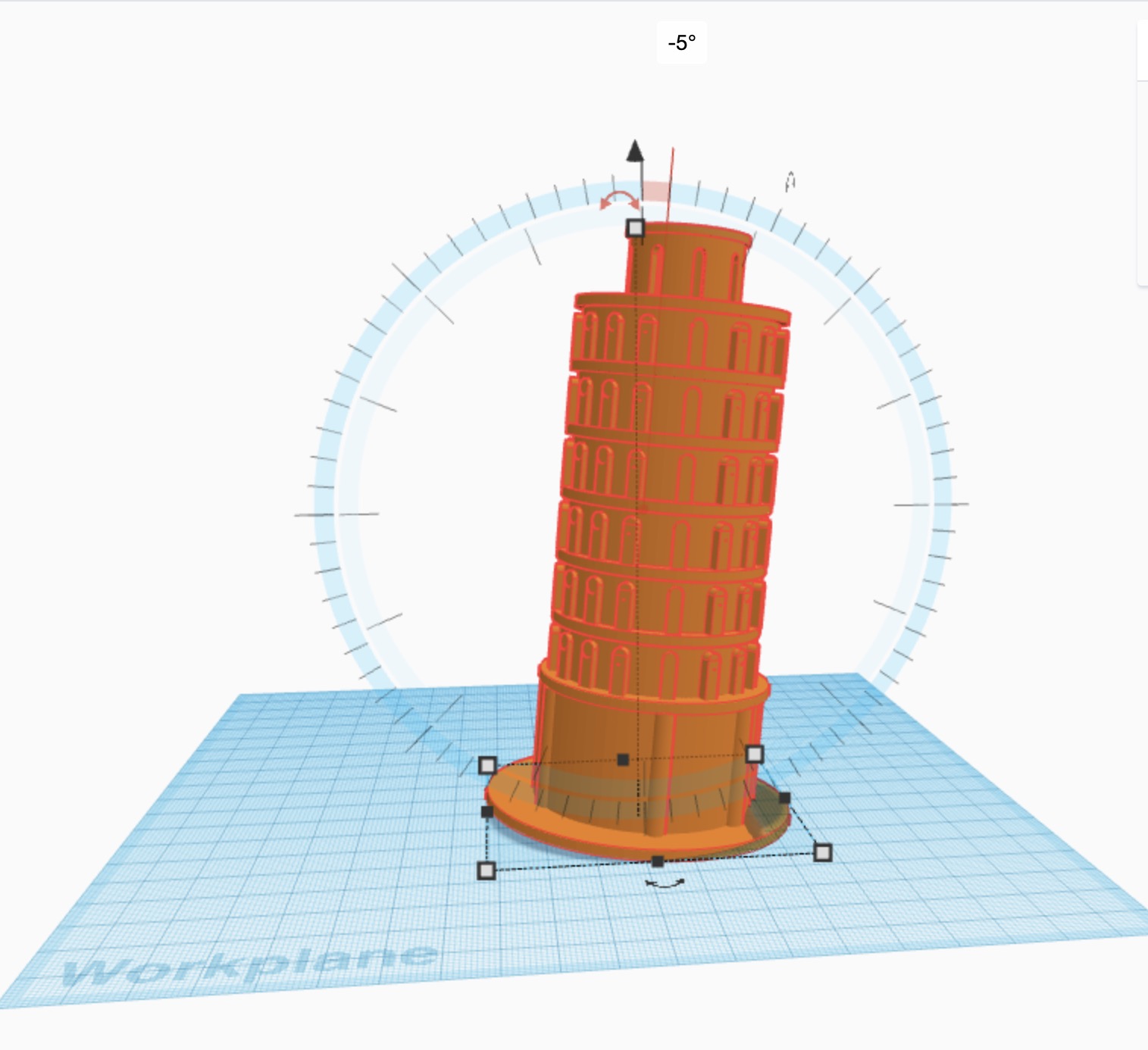
4 - Lastly, I grouped the whole tower one more time, and using the selection option I rotated the tower a bit to the side to make it leaning.
Final Results
Click here to download the file.