Final Project
This final two weeks were difficult, but with the help of our instructors and as a group, we made the project work. Coming up with an idea for a project that is expected to be fully functional from every other aspect is not an easy job to do, but it was possible with discussing and putting our ideas together, planning, and brainstorming. With our diverse interests, we agreed that our project must be beneficial in some way that may be used to enhance one another. P.S. You can find the design documentation process as well as how I connected the Adafurit to the BluFruit app on this website. The remainder of the final project documentation may be found on my project partner Ayah’s website.
Research
According to the World Health Organization, Bahrain air quality is considered unsafe to breathe. To raise awareness on sustainability and how our lifestyle is impacting the environment, we decided to build an air measuring system that can be implemented in your house in an aesthetic way, our logo reflects sustainability and how our daily choices are making an impact on the environment. Be a positive contribution to our environment by being aware of air pollutants and measures to eliminate air pollution in Bahrain. To understand more about your ecological footprint, click here.
Project Idea
Initial Idea
Our original idea was to design a plant pot that automatically waters itself based on soil moisture levels using a water pump that transports water from a water tank that collects water from moisture absorbing pellets that collect the humidity of the surrounding environment, and then display this data on an interactive screen that is attached to the pot with growth LEDs. In a sense, everything on the plant pot is done automatically. The sensors readings are displayed on an interactive screen that is place on the front profile of the plant pot.
Final Idea
“Potivia” a smart pot with a couple of sensors that monitors general air quality, temperature, humidity, dust, and plant moisture levels in interior environments, as well as providing the plant with growth lights. Potivia’s LEDs are moisture sensitive, so if they turn red, it signifies the soil is dry and it has to be watered until the LEDs turn green. In the same sense that the plant can notify its owner when to water it, the user may adjust the sensor sensitivity to fulfill the needs of the plant. The sensor readings are shown to the user by connecting the Adafruit to Bluetooth and displaying the data on the Blue Fruit app. Of course, this was a result of the fact that the initial idea implementation was difficult to finish in just two weeks, so we had to come up with some alternatives and eliminate a few specifications to be able to complete the project within the specific time period.
Materials
| Qty | Description | Price |
|---|---|---|
| 1 | Plant | 0.500 BD |
| 1 | Moisture Sensor | 7.500 BD |
| 1 | Half BreadBoards | 3.300 BD |
| 1 | Blu Tak | 0.500 BD |
| 1 | Dust Sensor | _ |
| 1 | Air quality Sensor | _ |
| 1 | Neo Pixel LEDs | _ |
Project Design
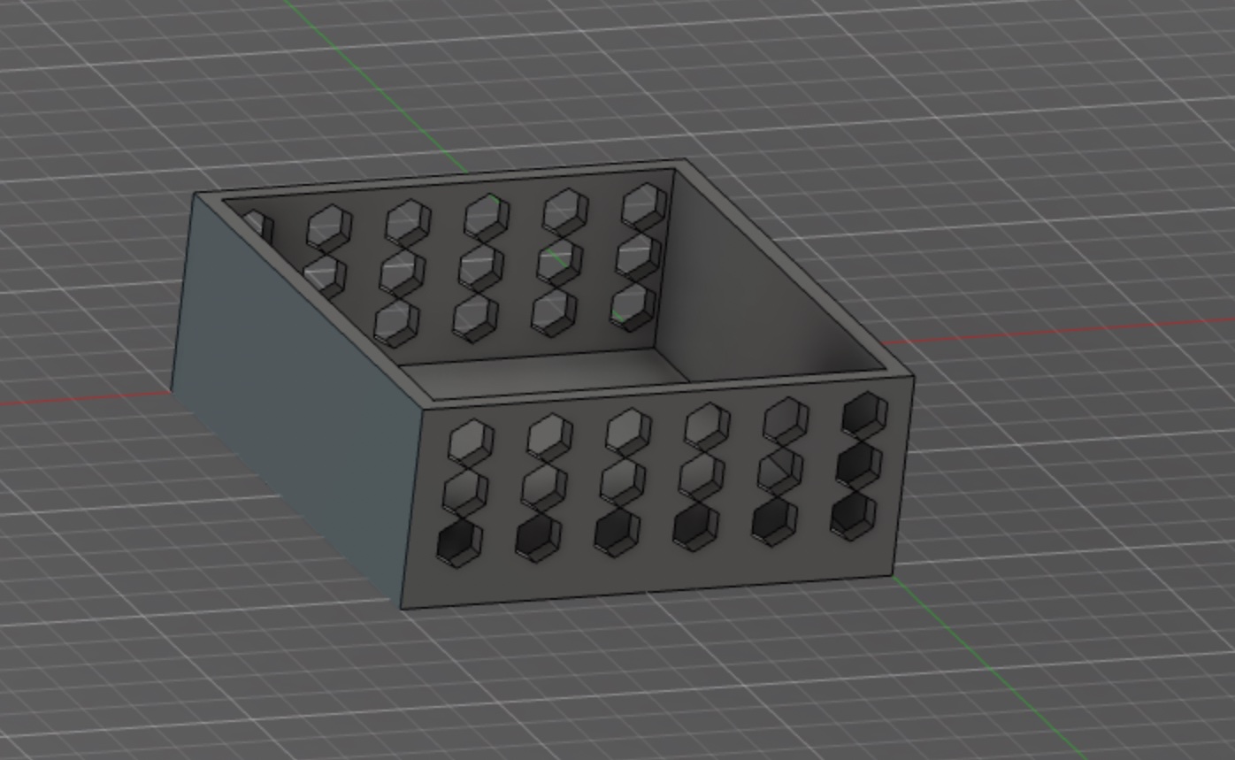
For the project design, we had to create a framework that could hold a pot and ensure that the structure and the pot fit together flawlessly.
Initial design
Additive Fabrication
We opted to print the design shown below in the 3D printer for the first initial model.
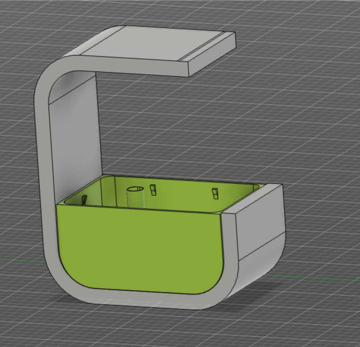 In addition, we designed an electronics compartment that would be positioned beneath the whole structure. We made sure to develop a honeycomb design of holes, which was very crucial because the majority of the sensors in our project are designed to detect the surrounding environment air quality.
Final Results
Click here to download the initial plant pot (structure + pot) design file.
Click here to download the initial electronics compartment design file.
Feedback
It was not practical because the design was far too large for the 3D printer to handle, and it would take many days to produce, so we had to come up with another option. This caused us to ponder and realize that, while 3D printing is efficient, it does not match with our project message of sustainability, therefore this was our opportunity to correct ourselves and come up with a sustainable alternative that actually fits the project ideas. Aside from that, the electronics compartment wasn’t really a practical idea because we were planning on placing it under the structure using Blu Tack, which is definitely not durable and will ruin the structure design, and because we were really concerned about our project’s aesthetic and the fact that it will be placed in an indoor room. So, we decided not to continue with this design because, first, we were going to modify the entire structure, second, we were going to 3D print it, which isn’t sustainable, and third, it didn’t match our project’s aesthetic.
Final Design
Because we needed to modify the pot structure/holder, we chose to change the design somewhat so that we could utilize a certain material. We decided on MDF. A big aspect of deciding on the material was determining if it was environmentally friendly and sustainable. Click here to learn more about MDF sustainability.
Additive Fabrication
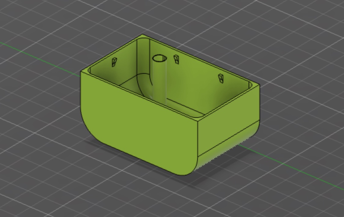
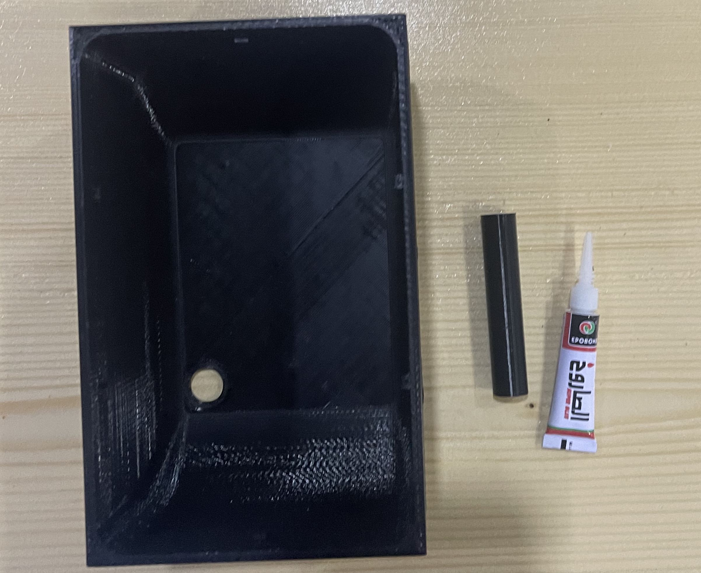
We were going to print the container that held the plant and its soil using additive manufacturing, and it had to be compact, watertight, and most importantly, durable.
So, using the same initial design, I separated it from the pot construction and made a hollow cylinder that extends all the way to the bottom to be able to link the moisture sensor to the electronics that will be placed in the final design’s below compartment.
Feedback
After printing it the first time, it was discovered that the cylinder was not totally closed and had an open area to its sides, which was an extreme fail because it meant we couldn’t use it, adding to that the cylinder fell and got sperated from the pot. Therefore, we then built a hollow cylinder of the same exact size and double-checked the design process before printing it and supergluing it to the hole left by the previous unsuccessful cylinder in the pot.
Final Results
Click here to Click here to download the final plant pot (pot) design file.
Subrtactive Fabrication
laser Cutter
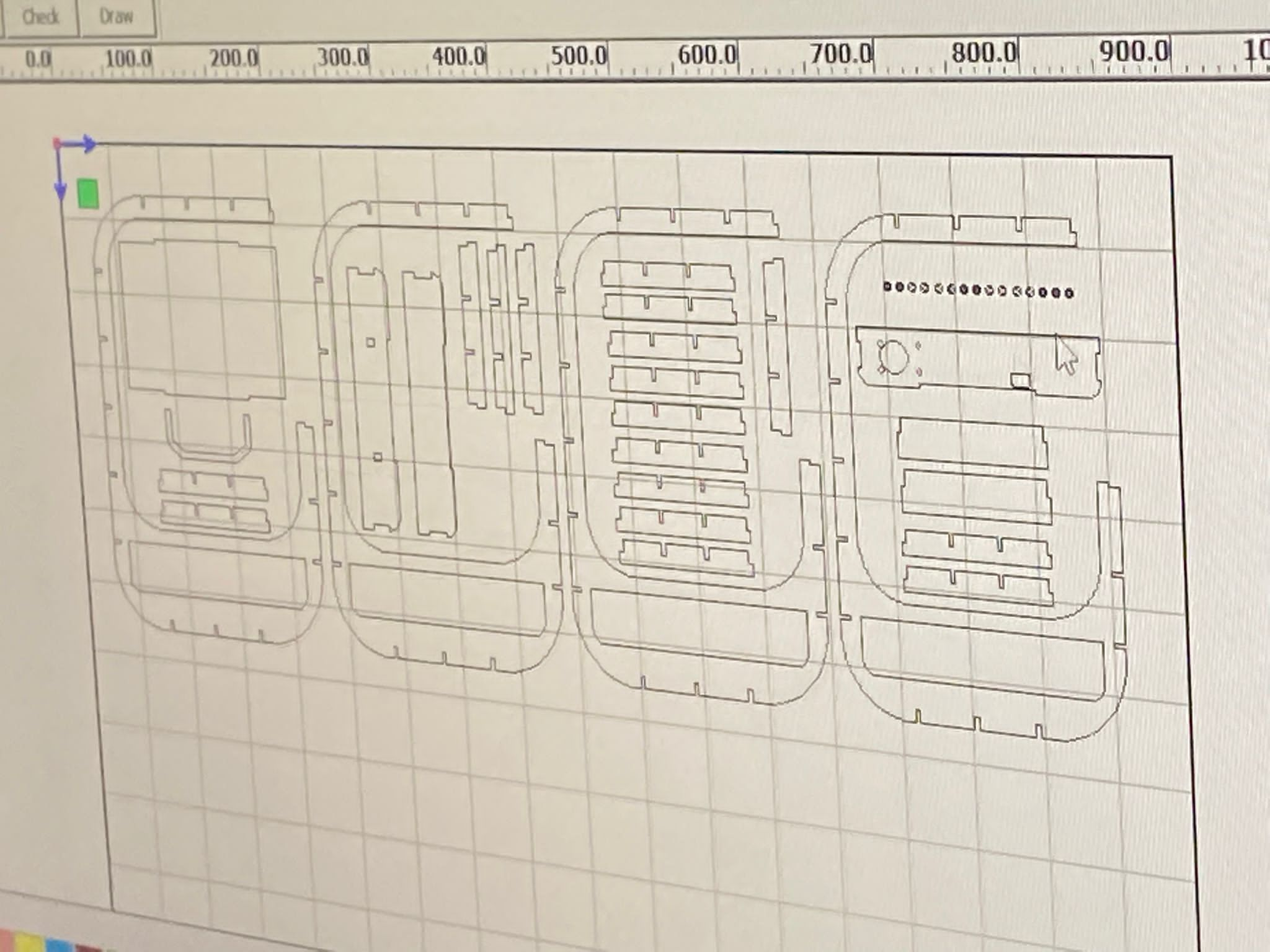
Click here to see how I used the laser cutter. Now that the first structure has failed, we must redesign it from the ground up, taking into account the measurements of the pots/potential electrical compartments/LEDs ensuring that the structure is of exact dimension so that everything fits properly into the structure of the plant pot. Taking all of this into account, the laser cutter was the ideal solution because we need precise measurements and were working with MDF. We constructed the structure or skeleton of the pot with the help of the instructor, and we chose to include openings all throughout the structure so the sensor can read accurate values. We included an electronic drawer within the structure to allow for quick adjustment or inspection of the elcotronics and sensor monitoring. Click here to Click here to download the final plant pot structure design file.
The image below shows how we positioned each component of the virtual MDF sheet’s design before submitting the file to the laser printer to begin the cutting process.
Assembling
To make the structure as durable as possible, we intended to make it a pressfit so that everything would be fused into the other without the need of nails or glue.
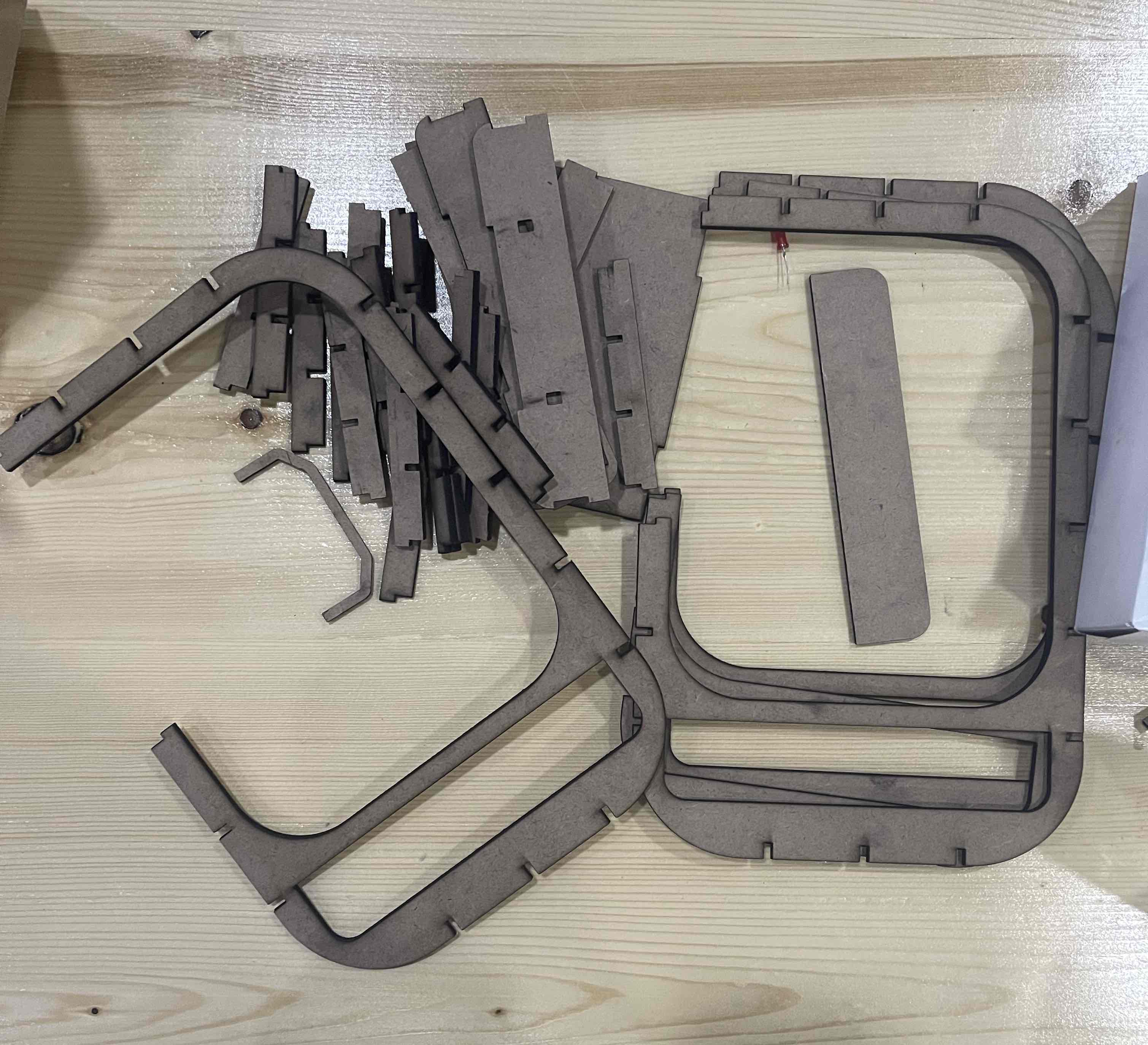
In the image below you see the all of the parts before assembling
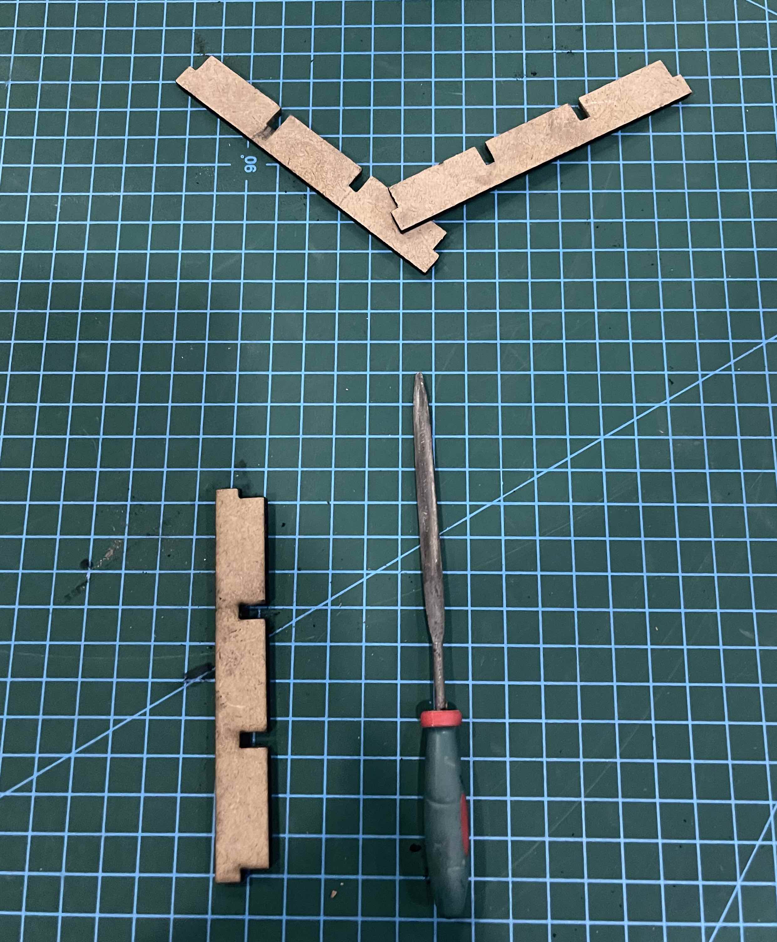
 When we first started assembling them, we had an issue with the joints not coming together; however, it was a simple repair; all we had to do was file the interior sections of the joints for them to be able to join together.
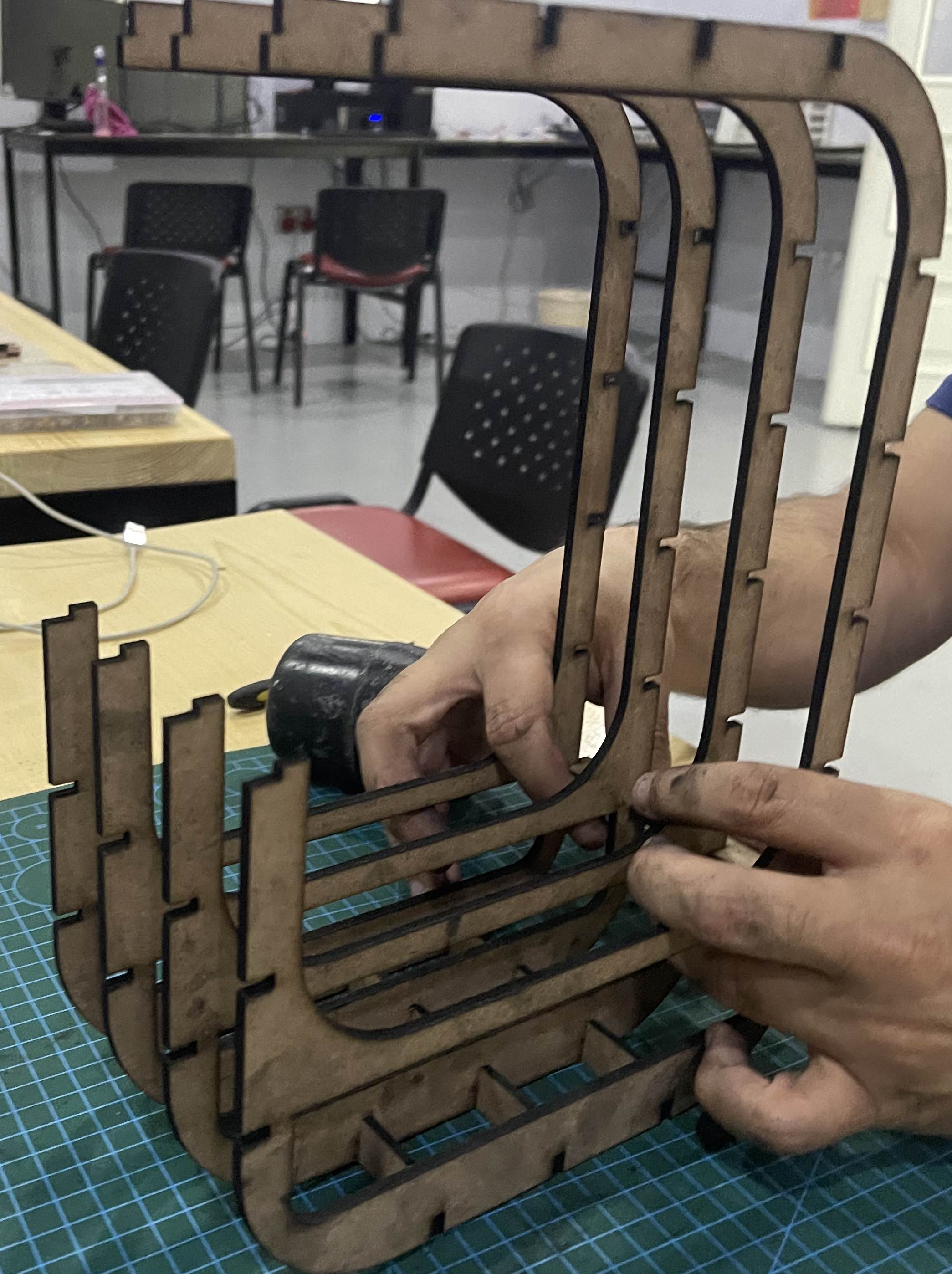
 In this image below you can see us assembling the parts after filing the joints.
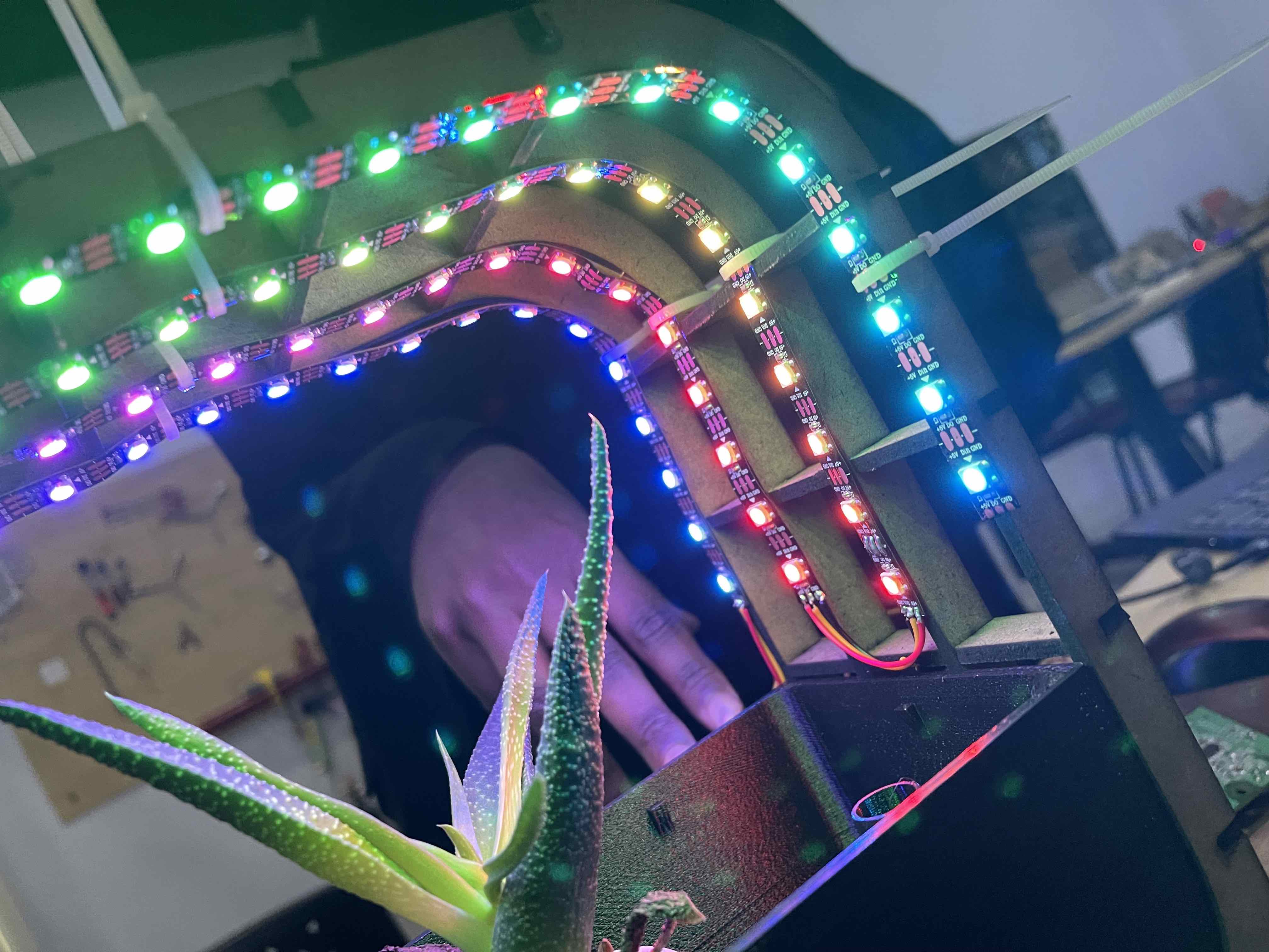
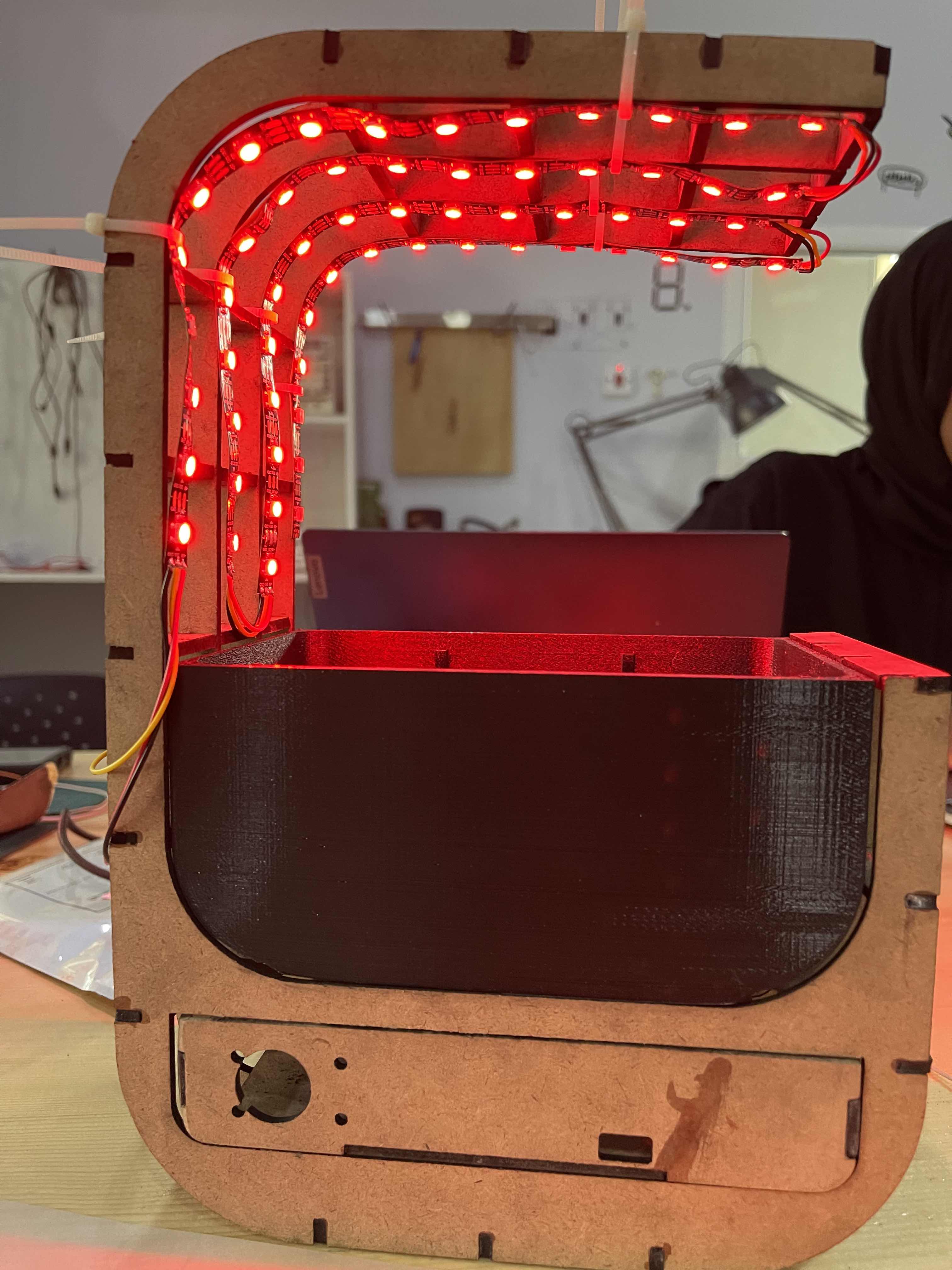
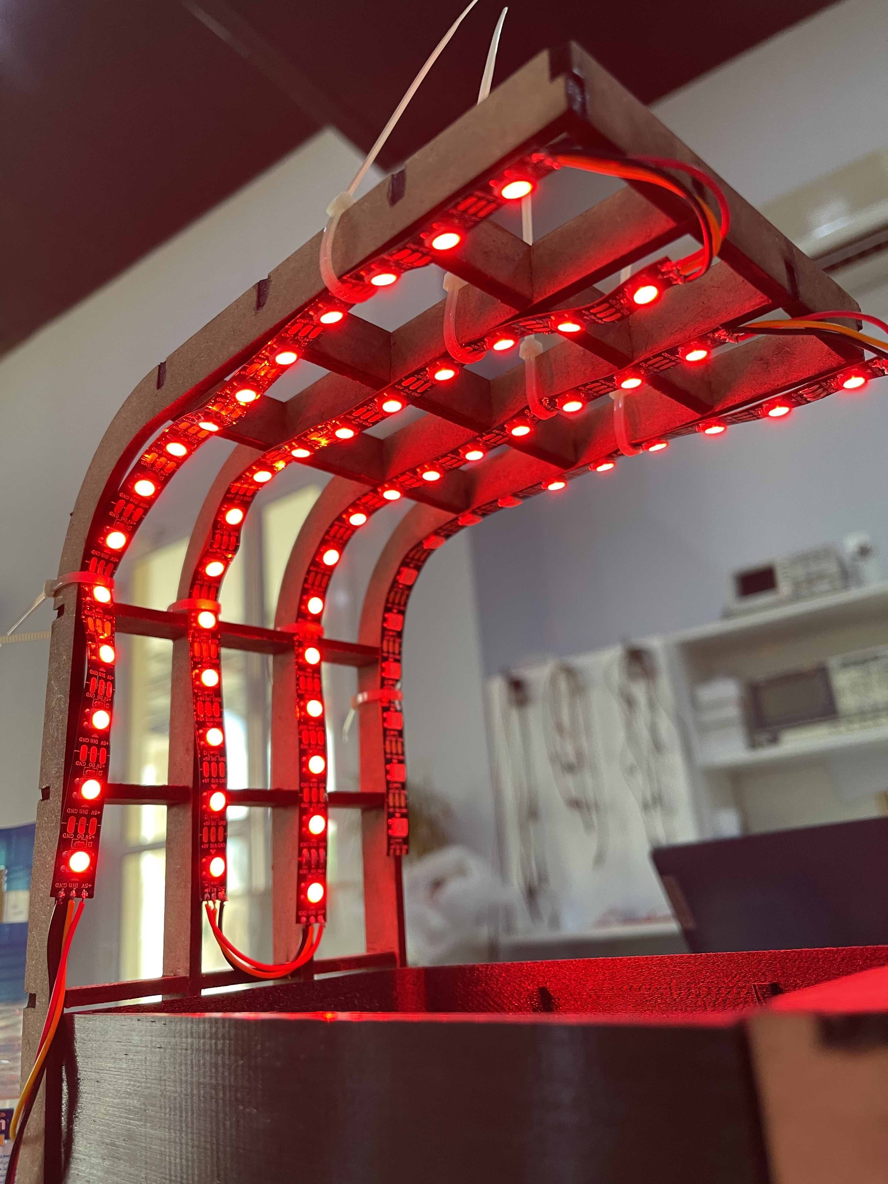
 We wanted to check how everything would appear before continuing on, so we originally assembled everything into position without using any non-removable components. We used zip ties to secure the LEDs in place, and we put the plant pot and electrical drawer in place as well.
The image below shows how we put everything together using zip ties and submitted the code to the adafruit for it to operate.
We wanted to check how everything would appear before continuing on, so we originally assembled everything into position without using any non-removable components. We used zip ties to secure the LEDs in place, and we put the plant pot and electrical drawer in place as well.
The image below shows how we put everything together using zip ties and submitted the code to the adafruit for it to operate.
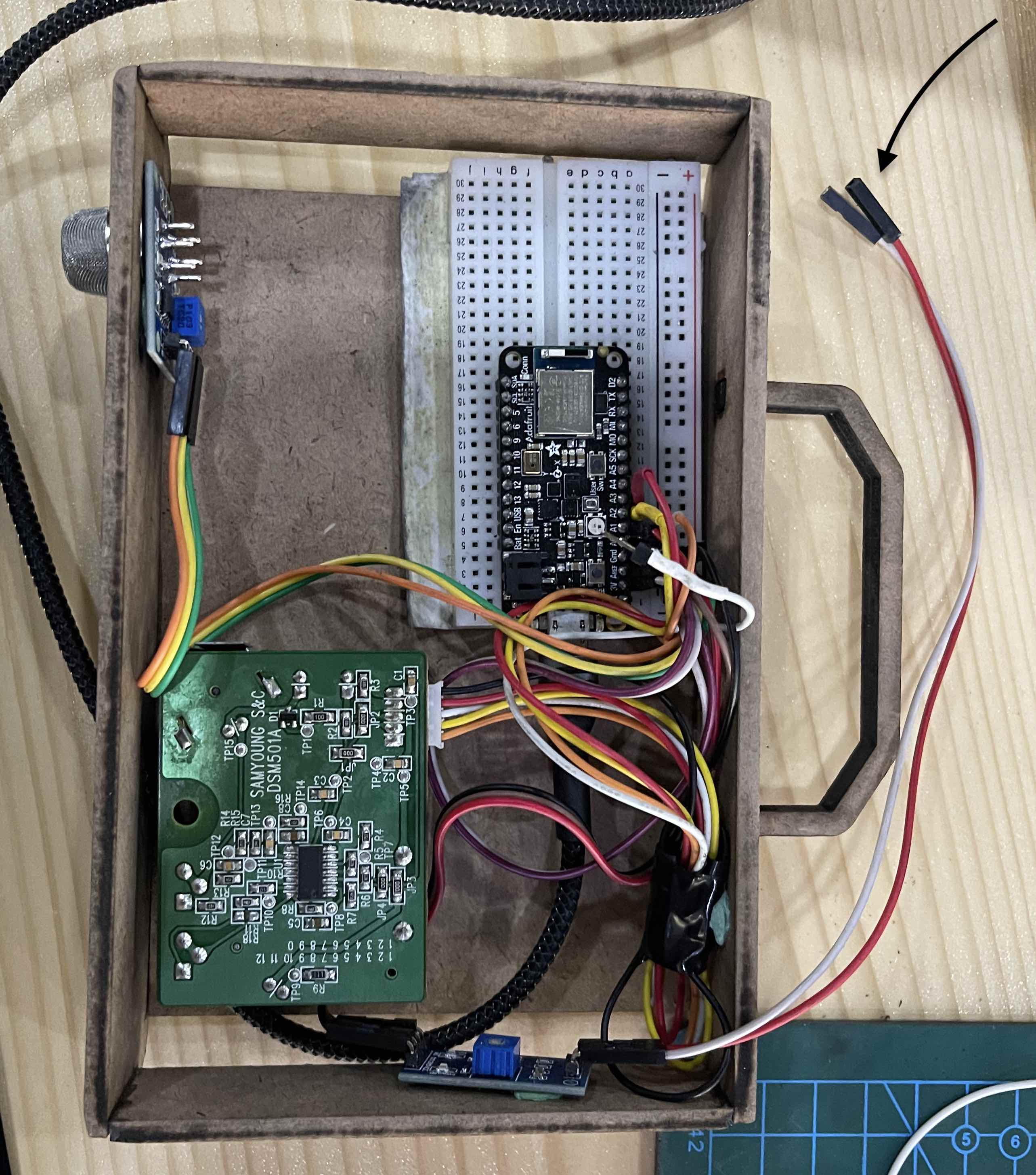
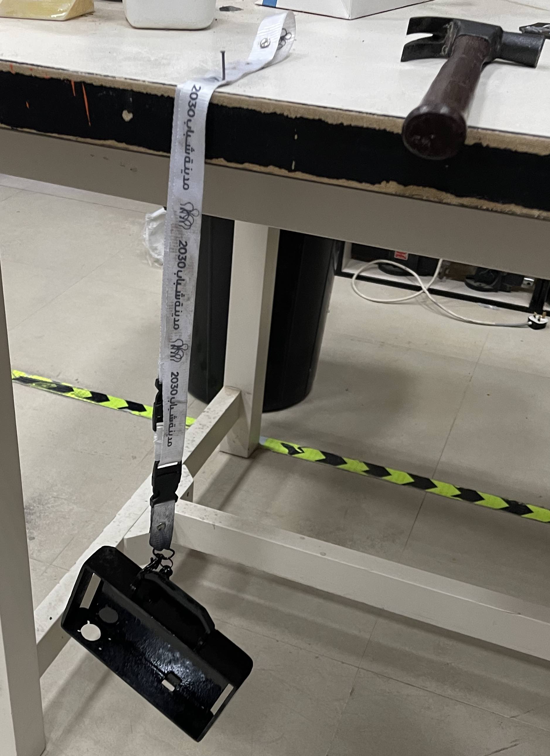
 We also needed to test the drawer’s functionality, so we used Blu Tack to secure the electronics in place. Take note of the arrow pointing on the extended wires that will link the moisture sensor and run all the way into the pot’s hollow cylinder. Check out the 3D model to understand more.
Painting
At this point, we wanted to paint the structure to match the style we were going for, so we used spray paint, which was the most efficient, quick, and elegant way to paint the MDF framework.
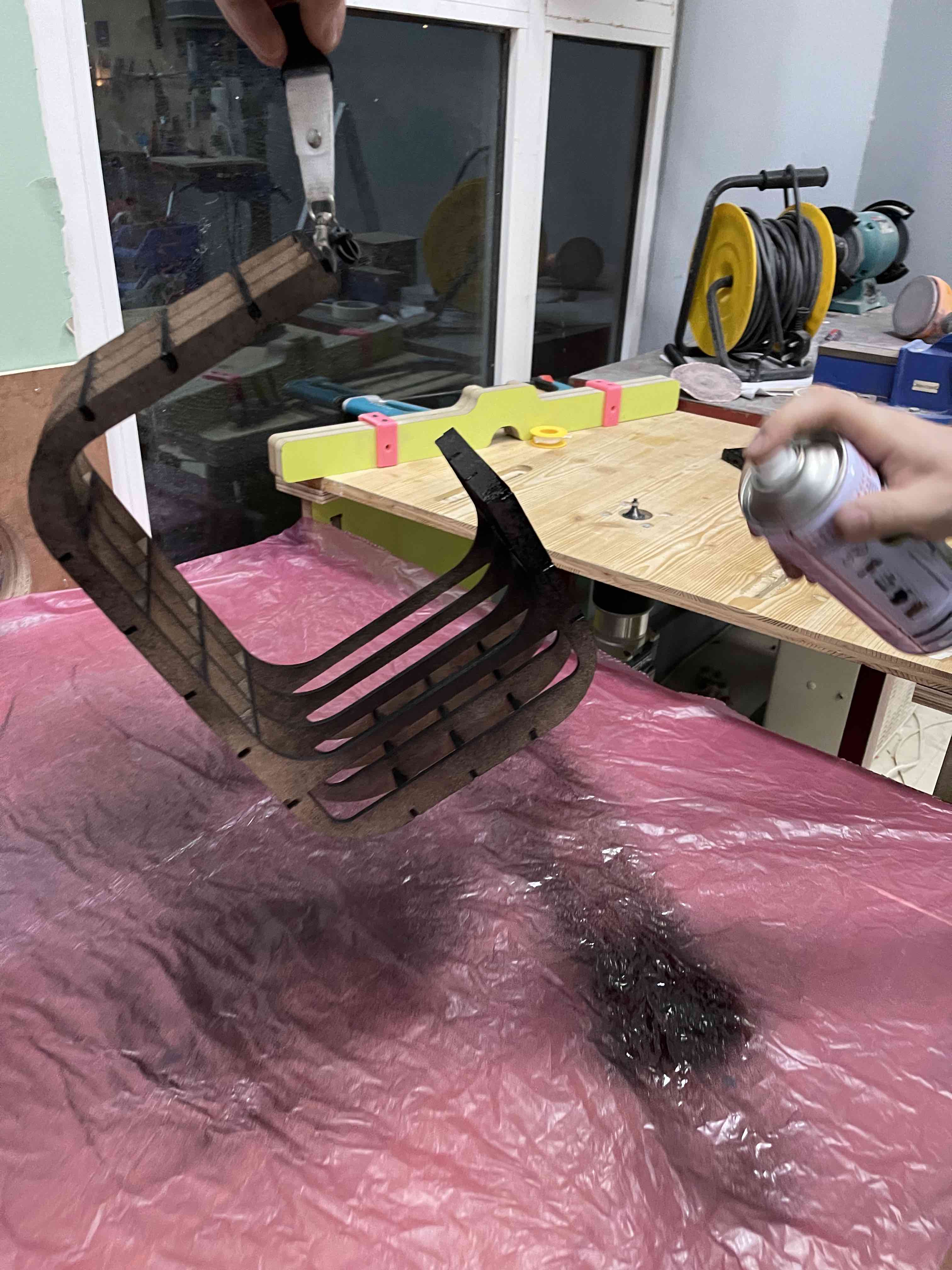 For the drawer, we had to hang it somewhere for the paint to dry, which resulted in a stain, similar to what happens when it dries on a flat surface.
Feedback
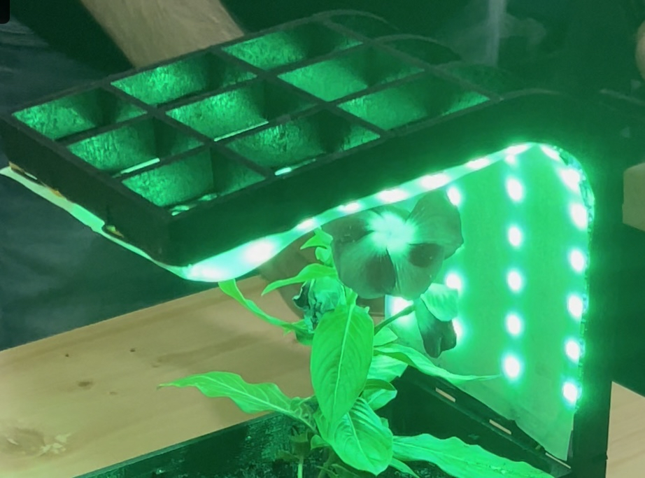
After the assembling we figured out that we didnt like how the LEDs looked so we decided to coverit. We tooka transparent plastic sheet took the LEDs placement measurements and sanded it to become translucents o the growth lights can still pass through.
Before look.
 After look
Vinyl Cutter
Click here to see how I used the vinyl cutter.
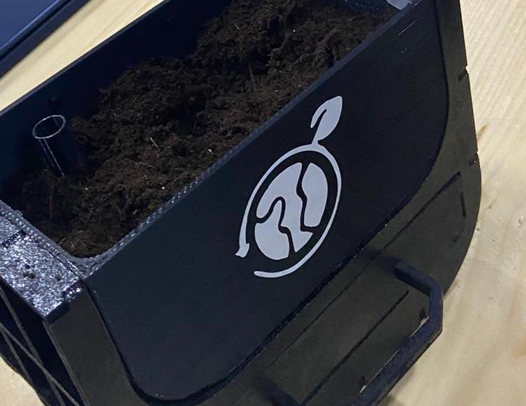
At this point, we wanted to create a logo that reflected sustainability while still giving the plant pot a beautiful look.
Here is the image that we decided to put
![]() First, we measured the pot to ensure that the sticker would fit in the center of it. We then operated the the vinyl cutter to cut the sticked=r and we proceeded to stick it on the front profile of the plant pot.
First, we measured the pot to ensure that the sticker would fit in the center of it. We then operated the the vinyl cutter to cut the sticked=r and we proceeded to stick it on the front profile of the plant pot.
Final Results
 Click here to download the logo.
App Connection
To connect the Adafruit to the Blufruit app, where all readings would be displayed, we had to first determine what type of connection the Adafruit accepts. We decided to use its Bluetooth connection, which will allow the Adafruit to connect to the app and display the readings using any phone that connects to the Adafruit and has a Blufruit app.
Bluetooth Connection
We used the ready made codes included in the Arduino compiler to figure out how to link the Adafruit to the Bluefruit app.
Using this code.
#include <bluefruit.h>
#include <Adafruit_LittleFS.h>
#include <InternalFileSystem.h>

// BLE Service
BLEDfu  bledfu;  // OTA DFU service
BLEDis  bledis;  // device information
BLEUart bleuart; // uart over ble
BLEBas  blebas;  // battery

void setup()
{
  Serial.begin(115200);

#if CFG_DEBUG
  // Blocking wait for connection when debug mode is enabled via IDE
  while ( !Serial ) yield();
#endif

  Serial.println("Bluefruit52 BLEUART Example");
  Serial.println("---------------------------\n");

  // Setup the BLE LED to be enabled on CONNECT
  // Note: This is actually the default behavior, but provided
  // here in case you want to control this LED manually via PIN 19
  Bluefruit.autoConnLed(true);

  // Config the peripheral connection with maximum bandwidth
  // more SRAM required by SoftDevice
  // Note: All config***() function must be called before begin()
  Bluefruit.configPrphBandwidth(BANDWIDTH_MAX);

  Bluefruit.begin();
  Bluefruit.setTxPower(4);    // Check bluefruit.h for supported values
  //Bluefruit.setName(getMcuUniqueID()); // useful testing with multiple central connections
  Bluefruit.Periph.setConnectCallback(connect_callback);
  Bluefruit.Periph.setDisconnectCallback(disconnect_callback);

  // To be consistent OTA DFU should be added first if it exists
  bledfu.begin();

  // Configure and Start Device Information Service
  bledis.setManufacturer("Adafruit Industries");
  bledis.setModel("Bluefruit Feather52");
  bledis.begin();

  // Configure and Start BLE Uart Service
  bleuart.begin();

  // Start BLE Battery Service
  blebas.begin();
  blebas.write(100);

  // Set up and start advertising
  startAdv();

  Serial.println("Please use Adafruit's Bluefruit LE app to connect in UART mode");
  Serial.println("Once connected, enter character(s) that you wish to send");
}

void startAdv(void)
{
  // Advertising packet
  Bluefruit.Advertising.addFlags(BLE_GAP_ADV_FLAGS_LE_ONLY_GENERAL_DISC_MODE);
  Bluefruit.Advertising.addTxPower();

  // Include bleuart 128-bit uuid
  Bluefruit.Advertising.addService(bleuart);

  // Secondary Scan Response packet (optional)
  // Since there is no room for 'Name' in Advertising packet
  Bluefruit.ScanResponse.addName();

  /* Start Advertising
   * - Enable auto advertising if disconnected
   * - Interval:  fast mode = 20 ms, slow mode = 152.5 ms
   * - Timeout for fast mode is 30 seconds
   * - Start(timeout) with timeout = 0 will advertise forever (until connected)
   *
   * For recommended advertising interval
   * https://developer.apple.com/library/content/qa/qa1931/_index.html
   */
  Bluefruit.Advertising.restartOnDisconnect(true);
  Bluefruit.Advertising.setInterval(32, 244);    // in unit of 0.625 ms
  Bluefruit.Advertising.setFastTimeout(30);      // number of seconds in fast mode
  Bluefruit.Advertising.start(0);                // 0 = Don't stop advertising after n seconds
}

void loop()
{
  // Forward data from HW Serial to BLEUART
  while (Serial.available())
  {
    // Delay to wait for enough input, since we have a limited transmission buffer
    delay(2);

    uint8_t buf[64];
    int count = Serial.readBytes(buf, sizeof(buf));
    bleuart.write( buf, count );
  }

  // Forward from BLEUART to HW Serial
  while ( bleuart.available() )
  {
    uint8_t ch;
    ch = (uint8_t) bleuart.read();
    Serial.write(ch);
  }
}

// callback invoked when central connects
void connect_callback(uint16_t conn_handle)
{
  // Get the reference to current connection
  BLEConnection* connection = Bluefruit.Connection(conn_handle);

  char central_name[32] = { 0 };
  connection->getPeerName(central_name, sizeof(central_name));

  Serial.print("Connected to ");
  Serial.println(central_name);
}

/**
 * Callback invoked when a connection is dropped
 * @param conn_handle connection where this event happens
 * @param reason is a BLE_HCI_STATUS_CODE which can be found in ble_hci.h
 */
void disconnect_callback(uint16_t conn_handle, uint8_t reason)
{
  (void) conn_handle;
  (void) reason;

  Serial.println();
  Serial.print("Disconnected, reason = 0x"); Serial.println(reason, HEX);
}
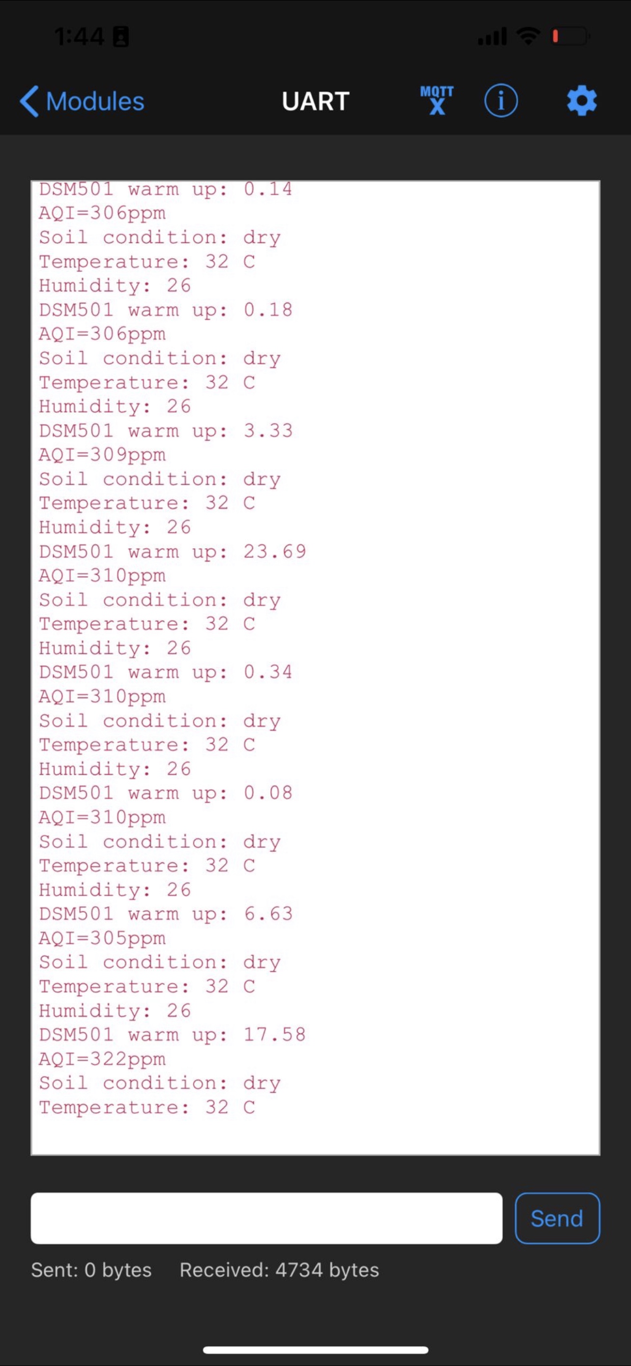
I then combined our project code with the code above, an used the code below to display the readings for all of the sesnors.
  bleuart.write("Temperature: ");
  char temperaturechar[16];
  itoa(temperature, temperaturechar, 10);
  bleuart.write(temperaturechar);
  bleuart.write(" C");
  bleuart.write(" ");
  bleuart.write('\n');
The temperature measurements were displayed using the sesnor reading in the preceding example. The identical set of code was utilized for all sensors and, of course, changine whatever required to be modified from writings.
The final results after successfully presenting all sensors readings on the phone app BlueFruit are shown below.
Project Demo
Please click here to follow the link to the short youtube video
Click here to view sensor readings after being connected to the phone app BlueFruit.