7. Input & Output device
This week, I learned how to build simple circuits and program them to do specific operations.
Reseach
What are Input and Output devices in circuits?
Input Devices
An input device responds to changes in the environment and produces a suitable electrical signal for processing in an electronic circuit. In all input devices, other forms of energy are transformed into electrical energy. Below are some common input devices with examples of how they might be used. - Microphone:A microphone generates a voltage when sound reaches it. It is used in a telephone or an intercom. - Thermistor: Its resistance increases when the temperature falls. Is used as a sensor in heating systems. - Light dependent resistor (LDR): Resistance decreases as light level rises. Used to control street lights.
Output Devices
Output devices in electronic systems transform electrical energy into another type of energy, such as light, sound or kinetic energy. Common output devices and their associated energy changes are shown in the table below.
| Device | Converts electrical energy to: |
|---|---|
| Buzzer | Sound |
| LoudSpeaker | Sound |
| LED | light |
| Motor | Kinetic |
What makes a functioning electrical circuit?
Every circuit is comprised of three major components: 1. a conductive “path,” such as wire, or printed etches on a circuit board; 2. a “source” of electrical power, such as a battery or household wall outlet (in my case I used the elctricity carried from the usb port to the adafruit through my laptop) 3. a “load” that needs electrical power to operate, such as a lamp. There are also two optional components that can be included in an electrical circuit. These are control devices and protective devices. Control and protective devices, however, are not required for a circuit to function. They are optional. Circuits are made up of two distinct elements:
- Active elements, which are defined as the sources of electrical energy.
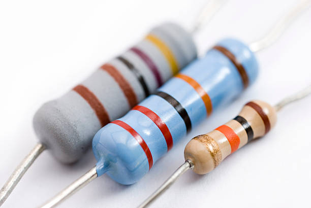
- Passive elements, which carry or use the electrical energy for some specific reason. For example: Resistors (two-terminal electrical component that implements electrical resistance as a circuit element, in my project as you can see below this section I used resistors to control the current flowing in the ciruit, it is important to use the right resistor in your circuit without it, the circuit won’t have a chance to lose the energy, and will return to the voltage source with lots of energy, which will typically screw up the voltage source), Below is an image of several resistors, each with its unique ohm measurement (resistors unit).
What are BreadBoards?
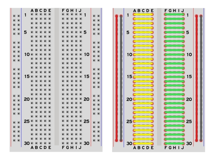
A breadboard (also known as a protoboard) serves as the basis for building and prototyping electronics. A breadboard enables the rapid and easy construction of temporary electrical circuits or the conduct of circuit design experiments. Breadboards make it simple for developers to connect components or cables by using rows and columns of internally linked spring clips beneath the perforated plastic casing. The grid is composed of precisely matched spring clip holes spaced 0.1′′ apart in both the X and Y - axis.
Breadboards needs to be understood prperly before starting to build a ciruit, one iimportant thing you need to know is that horizontal holes are linked and vertical holes are linked.
Below you can see how breadboard vertical and horizontal lines are connected.
Assignment
The purpose of today’s assignment is to connect my microprocessor adafruit that I discussed over the embedded programming week and how to code it using code blocks. In my first project, I’ll try to connect my Adafruit to a breadboard and program it to do a simple function.
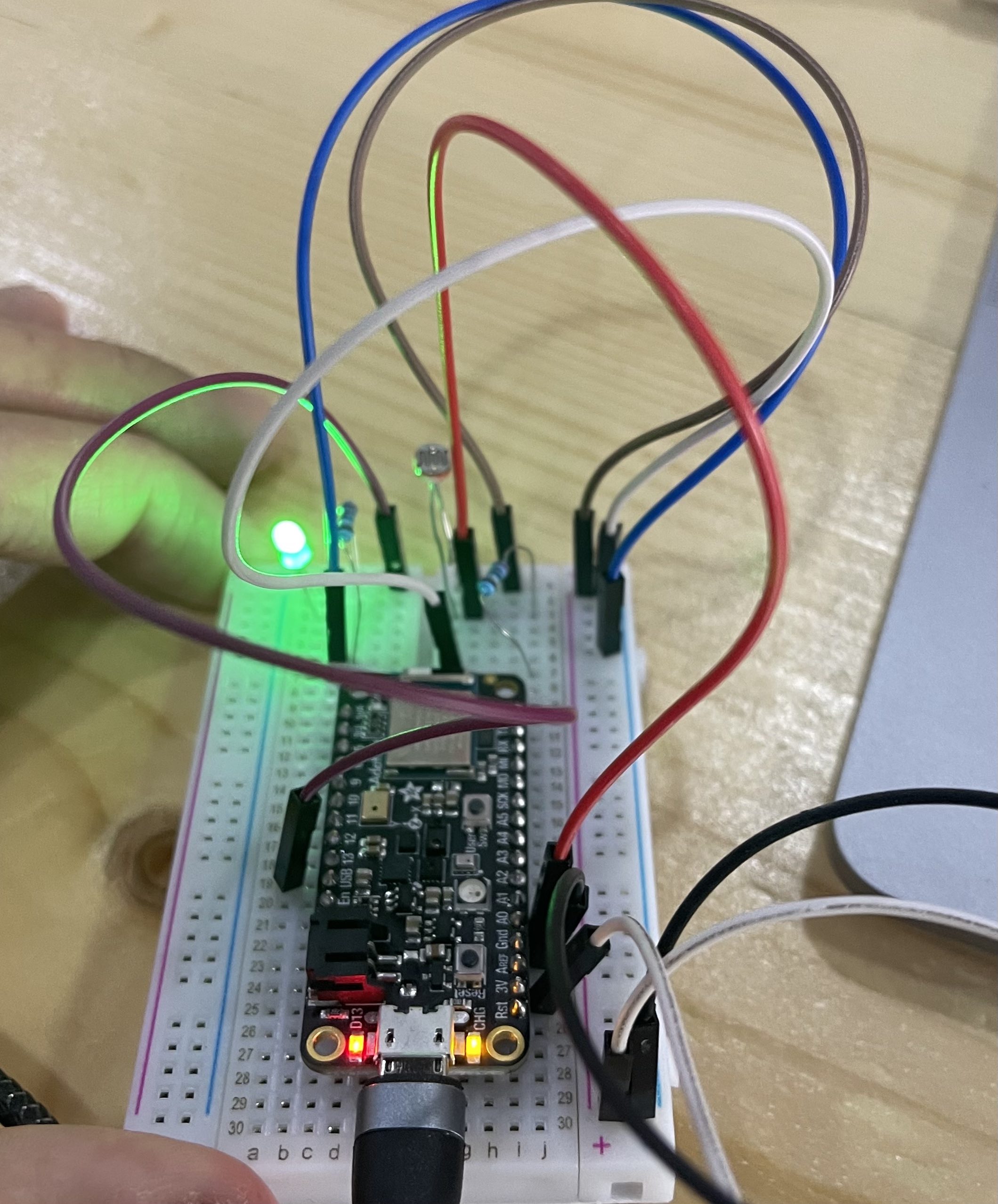
Project 1 - Light sensitivety sesnor (LED)
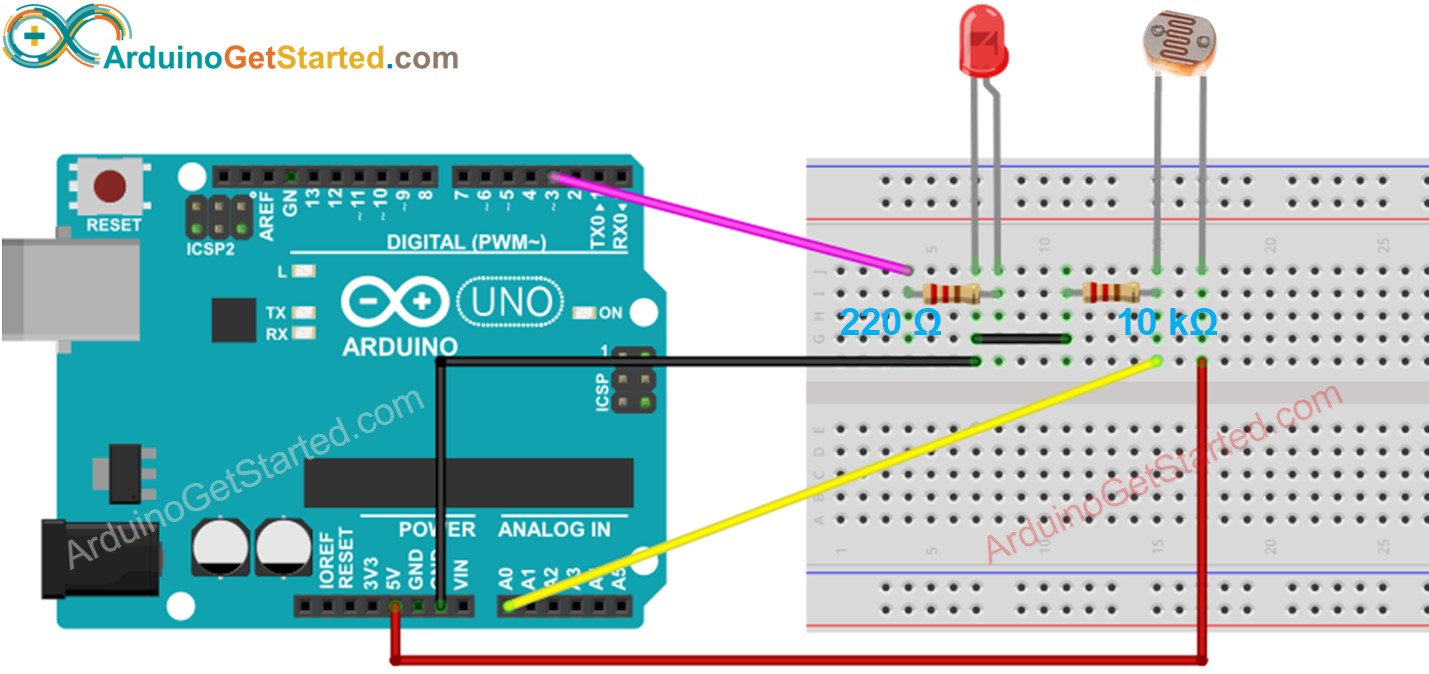
On my first project, I wanted to create a circuit with a sensor that detects the light sensitivity of its surroundings and turns on when the light is dim and off when there is adequate or bright light around it. First, I had to search for the components that I’m going to need, find the right resistors, and lookup how all of these component where gonna go on the breadboard, in a sense of to connect them. See below the table I created that lists out the components that I used in the circuit. I found this page to be helpful as it included a guide on how to connect everything to a breadboard and what components to use.
Components
| Components |
|---|
| Adafruit |
| Breadboard |
| photosensitive sensor |
| LED |
| Wires |
| Resistor 10K ohm |
| Resistor 220 ohm |
Connection
In this diagram you can see the circuit connection on the breadboard.
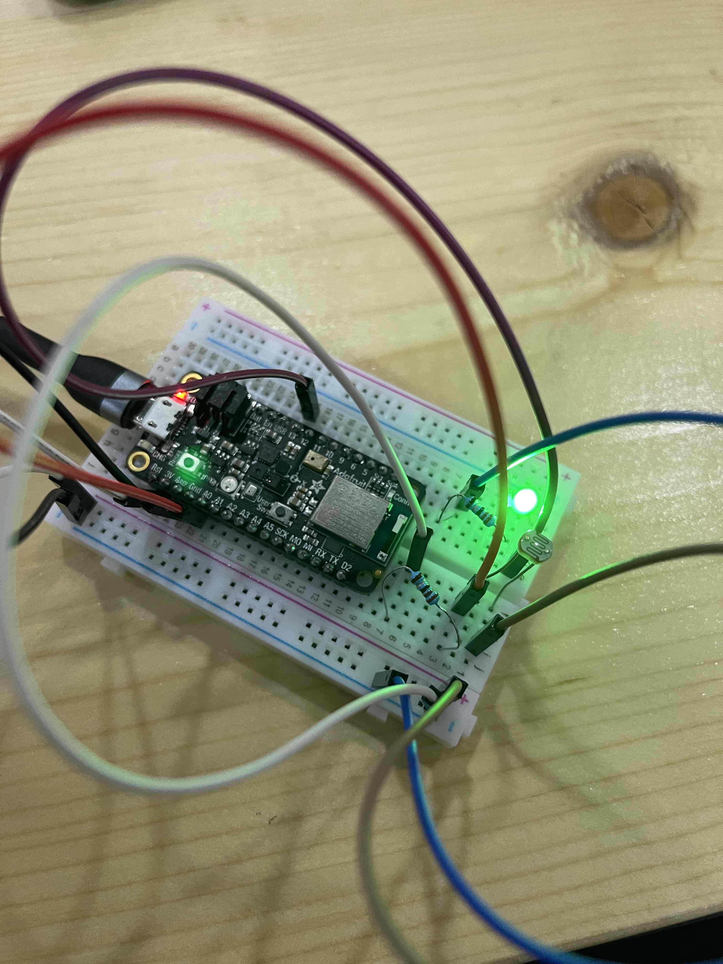
In this image you can see the circuit connection i made on my breadboard.
 You can see in this image the breadboard from another perspective
Coding
Below you can find the code that I used to program the Adafruit to perform the intended function check out this my embedded programming week page for more information on how to program the Adafruit.
// constants won't change
const int LIGHT_SENSOR_PIN = A4; // Arduino pin connected to light sensor's  pin
const int LED_PIN          = 12;  // Arduino pin connected to LED's pin
const int ANALOG_THRESHOLD = 10;

// variables will change:
int analogValue;

void setup() {
  pinMode(LED_PIN, OUTPUT); // set arduino pin to output mode
}

void loop() {
  analogValue = analogRead(LIGHT_SENSOR_PIN); // read the input on analog pin

  if(analogValue > ANALOG_THRESHOLD)
    digitalWrite(LED_PIN, HIGH); // turn on LED
  else
    digitalWrite(LED_PIN, LOW); // turn off LED
}
Final Results
As you can see in the video below that when I bring my phone flashlight near the sesnor the lED will turn off, and when I remove it, it will turn back on. perfroming the exact intended Operation. It is easy to modify the photosensitivie sesnor sensitivity by changing the ANALOG_THRESHOLD.
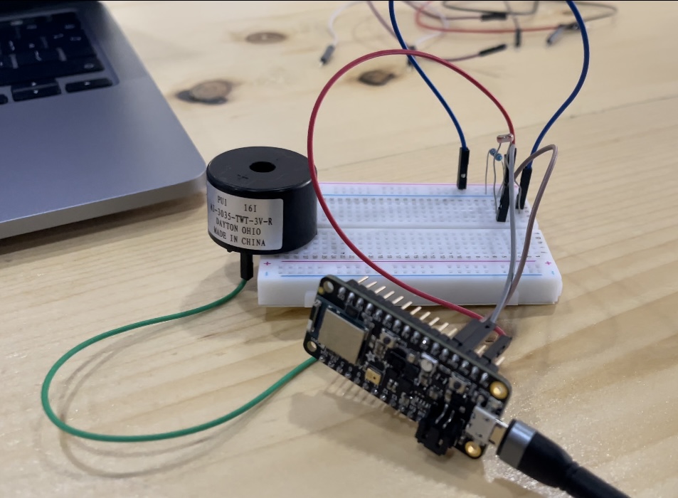
Project 2 - Light sensitivety sesnor (Buzzer)
For the second project, I created the same circuit from the previous project, however I instead of the LED i used a Buzzer.
Connection
In this image you can see the circuit connection i made on my breadboard.
Coding
// constants won't change
const int buzzer = A4; // Arduino pin connected to light sensor's  pin
  // Arduino pin connected to LED's pin
const int ANALOG_THRESHOLD = 10;


// variables will change:
int analogValue;


void setup() {
pinMode(buzzer,OUTPUT);
}

void loop() {
  analogValue = analogRead(LIGHT_SENSOR_PIN); // read the input on analog pin

  if(analogValue > ANALOG_THRESHOLD)

 tone(buzzer, 1000); // tone() is the main function to use with a buzzer, it takes 2 or 3 parameteres (buzzer pin, sound frequency, duration)
 delay(1000);
 tone(buzzer, 2000); // You can also use noTone() to stop the sound it takes 1 parametere which is the buzzer pin
 delay(1000); // turn on LED
  else
    noTone();
}
Final Results
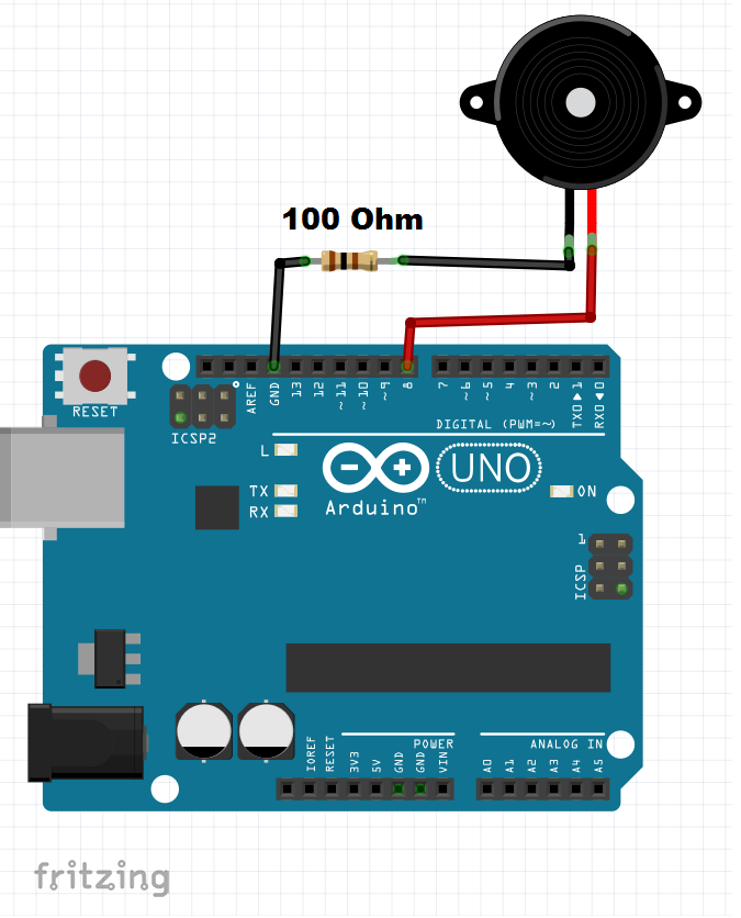
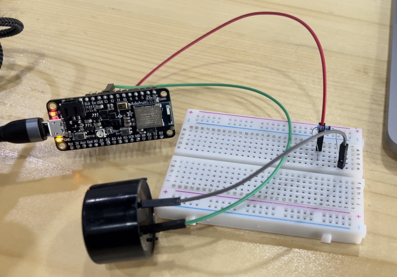
Project 3 - Buzzer Siren 🚨
For the third project, I opted to put a buzzer in my circuit to make a tone, which is the first time I’ve used a buzzer. Make a siren or alarm comparable to those used for fire alarms. I found this Youtube Tutorial
Components
| Components |
|---|
| Adafruit |
| Breadboard |
| Buzzer |
| Resistor 100 ohm |
| Wires |
Connections
In this diagram you can see the circuit connection on the breadboard.
 In this image you can see the circuit connection i made on my breadboard.
Coding
int buzzer = 8;

void setup() {
pinMode(buzzer,OUTPUT);

}

void loop() {

 tone(buzzer, 1000); // tone() is the main function to use with a buzzer, it takes 2 or 3 parameteres (buzzer pin, sound frequency, duration)
 delay(1000);
 tone(buzzer, 2000); // You can also use noTone() to stop the sound it takes 1 parametere which is the buzzer pin
 delay(1000);

}
Final Results
Project 4 - Star Wars Theme Buzzer
For the fourth project, I made the exact same thing as the second project, however I used a different cond to output a star wars them tone from the buzzer. Scroll to the previous project to see how I made the connections on the breadbard an what components I used.
Coding
const int c = 261;
const int d = 294;
const int e = 329;
const int f = 349;
const int g = 391;
const int gS = 415;
const int a = 440;
const int aS = 455;
const int b = 466;
const int cH = 523;
const int cSH = 554;
const int dH = 587;
const int dSH = 622;
const int eH = 659;
const int fH = 698;
const int fSH = 740;
const int gH = 784;
const int gSH = 830;
const int aH = 880;

const int buzzerPin = 13;
const int ledPin1 = 12;
const int ledPin2 = 13;

int counter = 0;

void setup()
{
 //Setup pin modes
 pinMode(buzzerPin, OUTPUT);
 pinMode(ledPin1, OUTPUT);
 pinMode(ledPin2, OUTPUT);
}

void loop()
{

 //Play first section
 firstSection();

 //Play second section
 secondSection();

 //Variant 1
 beep(f, 250);
 beep(gS, 500);
 beep(f, 350);
 beep(a, 125);
 beep(cH, 500);
 beep(a, 375);
 beep(cH, 125);
 beep(eH, 650);

 delay(500);

 //Repeat second section
 secondSection();

 //Variant 2
 beep(f, 250);
 beep(gS, 500);
 beep(f, 375);
 beep(cH, 125);
 beep(a, 500);
 beep(f, 375);
 beep(cH, 125);
 beep(a, 650);

 delay(650);
}

void beep(int note, int duration)
{
 //Play tone on buzzerPin
 tone(buzzerPin, note, duration);

 //Play different LED depending on value of 'counter'
 if(counter % 2 == 0)
 {
 digitalWrite(ledPin1, HIGH);
 delay(duration);
 digitalWrite(ledPin1, LOW);
 }else
 {
 digitalWrite(ledPin2, HIGH);
 delay(duration);
 digitalWrite(ledPin2, LOW);
 }

 //Stop tone on buzzerPin
 noTone(buzzerPin);

 delay(50);

 //Increment counter
 counter++;
}

void firstSection()
{
 beep(a, 500);
 beep(a, 500);
 beep(a, 500);
 beep(f, 350);
 beep(cH, 150);
 beep(a, 500);
 beep(f, 350);
 beep(cH, 150);
 beep(a, 650);

 delay(500);

 beep(eH, 500);
 beep(eH, 500);
 beep(eH, 500);
 beep(fH, 350);
 beep(cH, 150);
 beep(gS, 500);
 beep(f, 350);
 beep(cH, 150);
 beep(a, 650);

 delay(500);
}

void secondSection()
{
 beep(aH, 500);
 beep(a, 300);
 beep(a, 150);
 beep(aH, 500);
 beep(gSH, 325);
 beep(gH, 175);
 beep(fSH, 125);
 beep(fH, 125);
 beep(fSH, 250);

 delay(325);

 beep(aS, 250);
 beep(dSH, 500);
 beep(dH, 325);
 beep(cSH, 175);
 beep(cH, 125);
 beep(b, 125);
 beep(cH, 250);

 delay(350);
}
Final Results
Feedback
The most difficult challenge that I faced was making the code work for my Adafruit, even though I found some online programs that I could use, it needed to be redesigned to meet my needs. Also, choosing the right resistor required some calculations since I was using a different microprocessor than those i found on the internet where most used an Arduino that, so I was unfamiliar with it, but my instructor was helpful enough to guide me in choosing the right resistor.