8. Moulding and casting
This week I learned how to use fifferent materials to mould and cast my own CAD design.
What is Moulding?
Moulding or Mouldmaking is the act of creating the cavity / form that carries a negative or reverse impression of an original model. Molds can be made of a rigid material, such as plaster or plastic resin or more commonly, a flexible material such as rubber. The material to use should be chosen considering the material of the model, the material to be used to make castings, and whether there are any undercuts.
Moulding Uses
In molding, the material is injected into a form typically made of metal. There are a few different options in injection molding. Common types include: - Thin wall molding: This process centers on making the wall of the part as thin as possible to create a lighter, more flexible piece. Typically, the width of the wall itself is under .025 of an inch. - Gas-assisted injection molding: In some injection molding cases, materials can shift, leading to distorted end products. Gas-assisted injection allows the creator to blast a hole or hollow point into the mold and ensure it does not distort as it cools. - 3D Printing: While it’s a category in and of itself, 3D printing is a type of injection molding frequently used in prototyping for its relatively low cost and wide availability.
What is Casting?
Casting is the act of pouring liquid material into the cavity of a mold. After a period of time, this liquid will cure via chemical reaction or cooling. The solidified part is also known as a casting, which is ejected or broken out of the mold to complete the process. Casting materials are usually metals or various cold setting materials that cure after mixing two or more components together; examples are epoxy, concrete, plaster and clay.
Casting Uses
In casting, the liquid metal is poured into a form made of silicone rubber or a similar material. Die casting has two primary types: - Hot chamber die casting: This is the more common form of die casting. In this, the material is heated inside the casting chamber, hence the term “hot chamber.” As it eliminates the need to melt the metal elsewhere, it’s the preferred method. - Cold chamber die casting: Cold chamber die casting involves liquefying the metal first and then putting it into the cold chamber for funneling into the die. This is typically a process completed for metals with high melting points.
Group Assignment
For the group assignment what we did was choose a material, gather inofrmation about that material it terms of it’s name and synonyms, saftey precautions, the Method and that includes material to water ratio, work time, cure time
Reasearch
Material
Gypsum
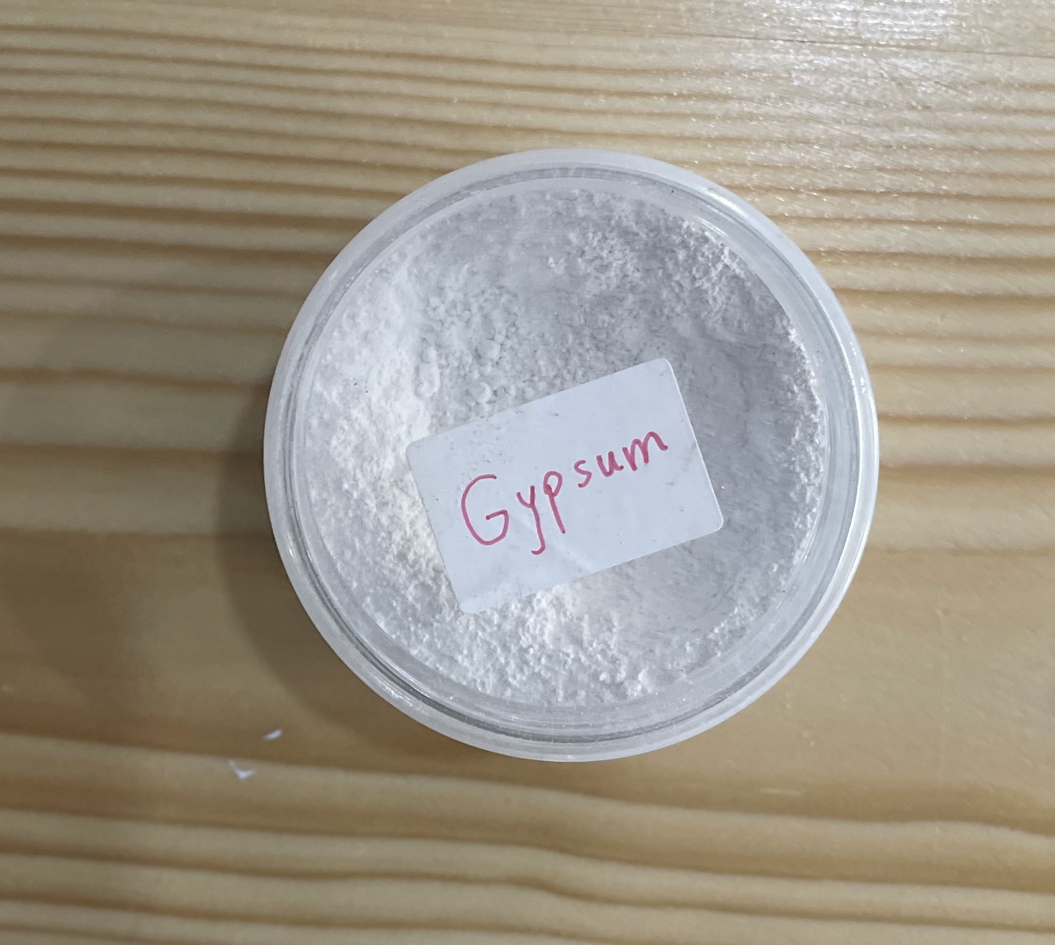
Other synonyms
Calcium(II) sulfate dihydrate, Gypsum stone, Hydrated calcium sulfate, Mineral white
Safety Precautions
- Do not handle until the safety information presented in this SDS has been read and understood.
- Do not breathe dusts or mists. Do not eat, drink or smoke while manually handling this product. Wash skin thoroughly after manually handling.
- If swallowed: If ingested, intestinal obstruction may occur if the material hardens. If gastrointestinal discomfort occurs and if person is conscious, give a large quantity of water and induce vomiting; however, never attempt to make an unconscious person drink or vomit.
- If on skin (or hair): Rinse skin after manually handling and wash contaminated clothing if there is potential for direct skin contact before reuse.
- If inhaled excessively: Remove person to fresh air and keep comfortable for breathing.
- If in eyes: Rinse cautiously with water for several minutes. Remove contact lenses, if present and easy to do, and continue rinsing.
- If exposed, concerned, unwell or irritation of the eyes, skin, mouth or throat/nasal passage persist: Get medical attention.
- Wear eye protection and respiratory protection following this SDS, NIOSH guidelines and other applicable regulations. Use protective gloves if manually handling the product.
- Avoid creating dust when handling, using or storing. Use with adequate ventilation to keep exposure below recommended exposure limits.
- Dispose of product in accordance with local, regional, national or international regulations.
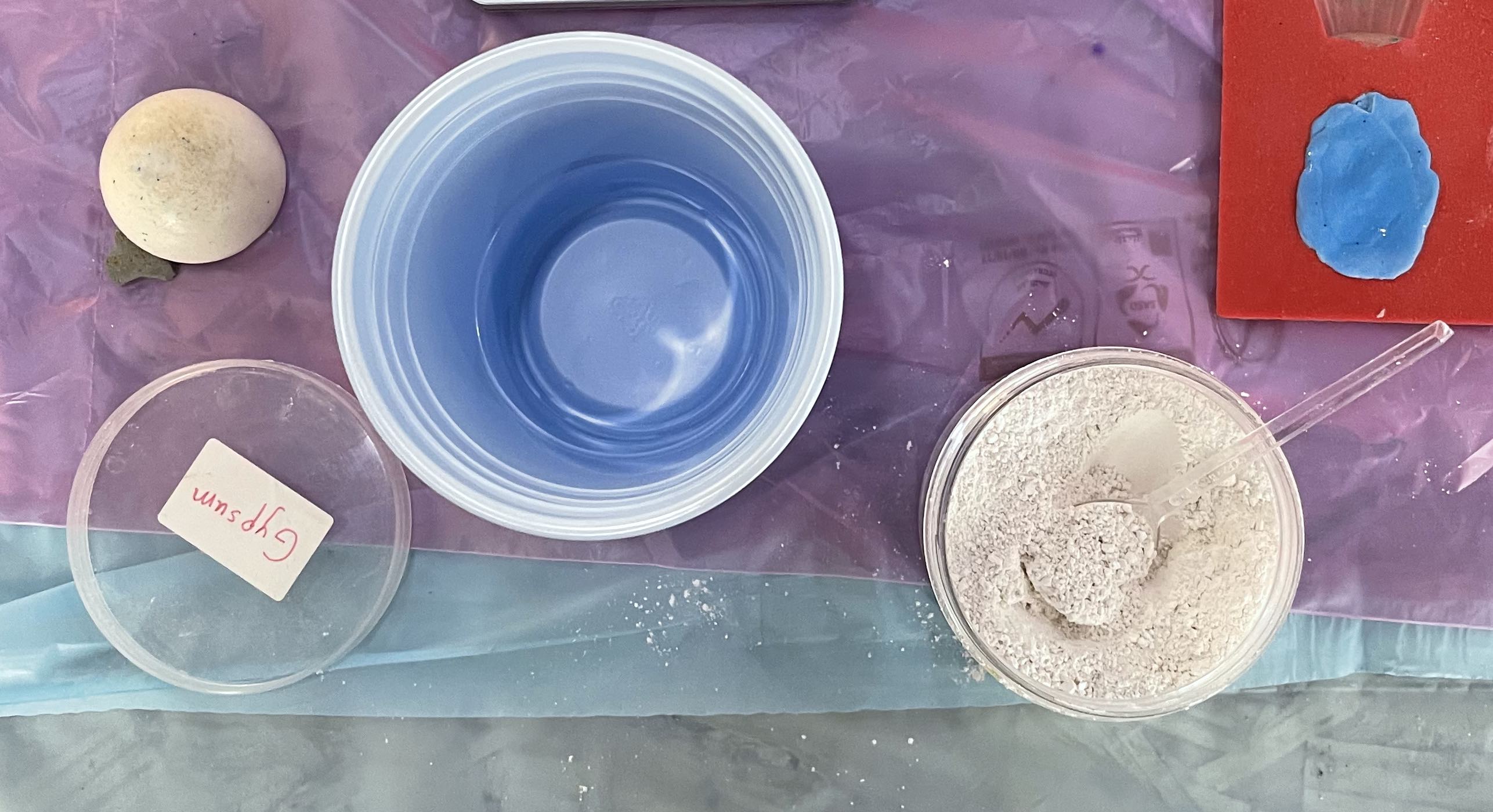
Method
- Add water to the bucket gypsum to water (4:3)
- Add plaster slowly until plaster stop absorbing water
- Let it stay in bucket 5-10 min (do not mix)
- Mix carefully with hands and pour to the mold immediately
- Shake mold from side to side to release an air pockets for face for the stone
- Working time of 15 minutes, demold in 1 hour, complete cure in 24 to 48 hours.
References
Reference 1 Reference 2 Referecne 3 Reference 4 Reference 5 You may find the rest of the group assignment content on Qassims’s website
Process
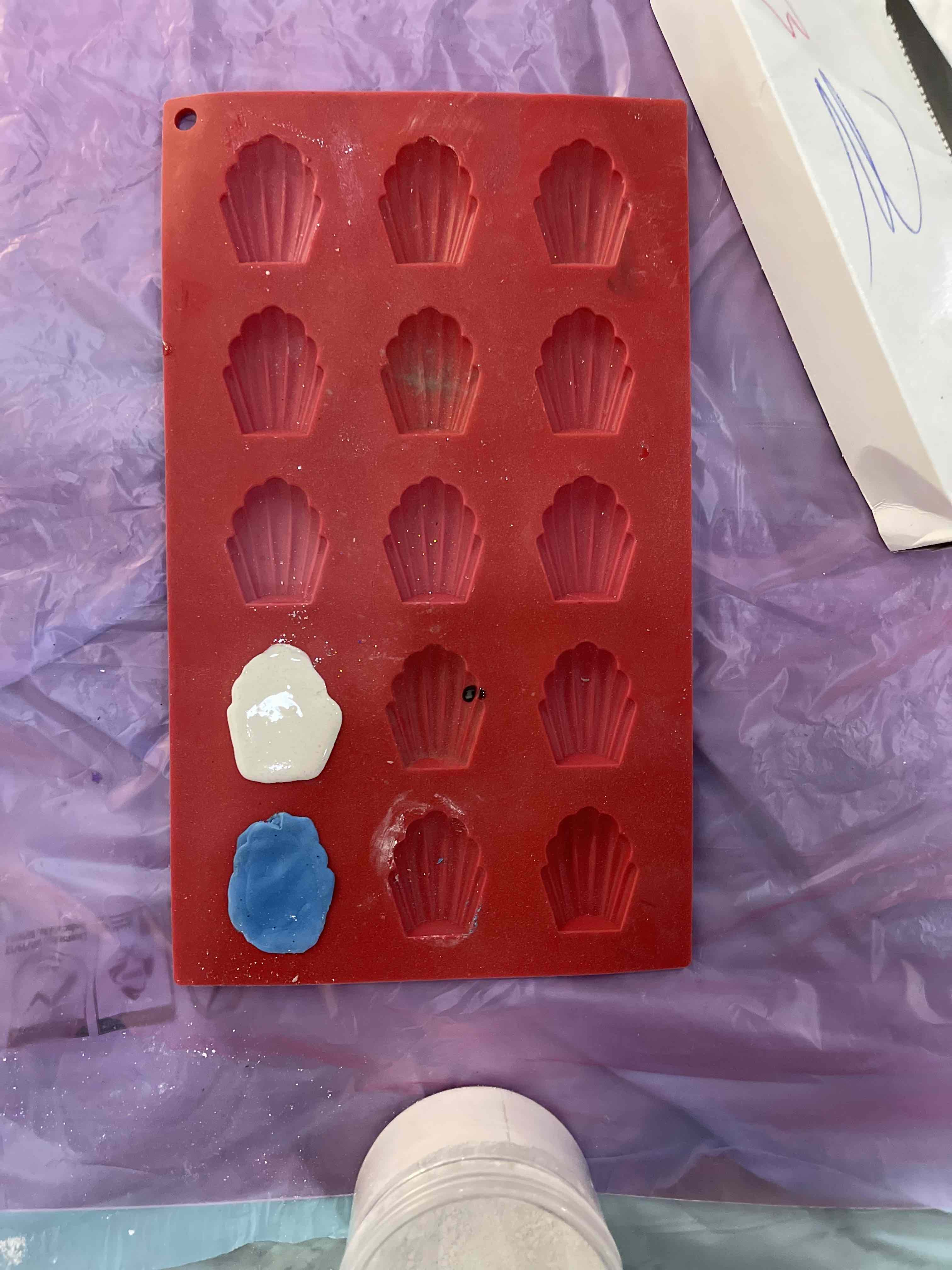
I first added four parts Gypsum and 3 parts water and let it sit for 5 mins before mising them together,
 Next I mixed them together unit it became this white liquid
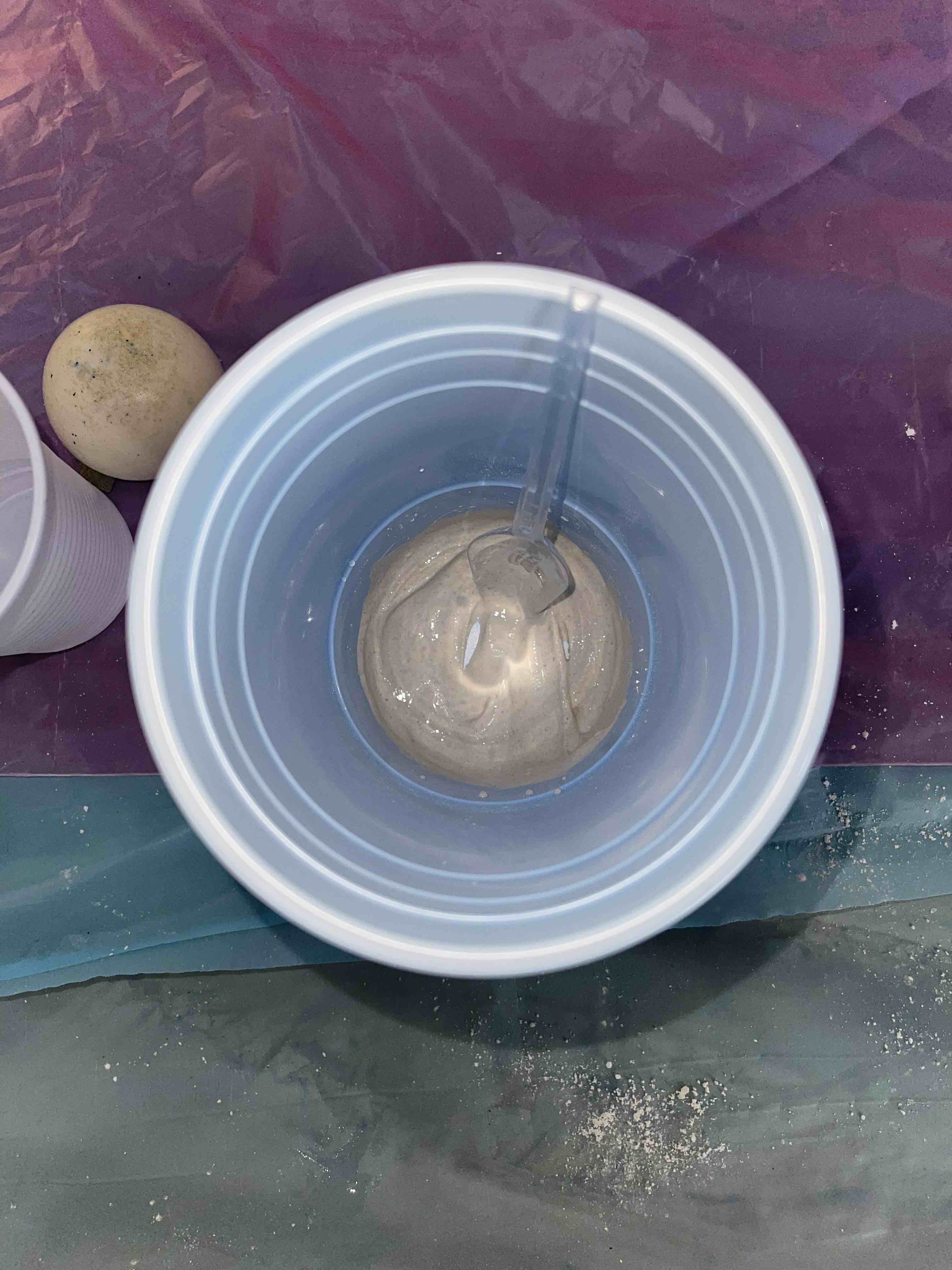 And finally i poured the concoction in the mold and left. it for the recomended hours before finally taking it out to a single solid piece
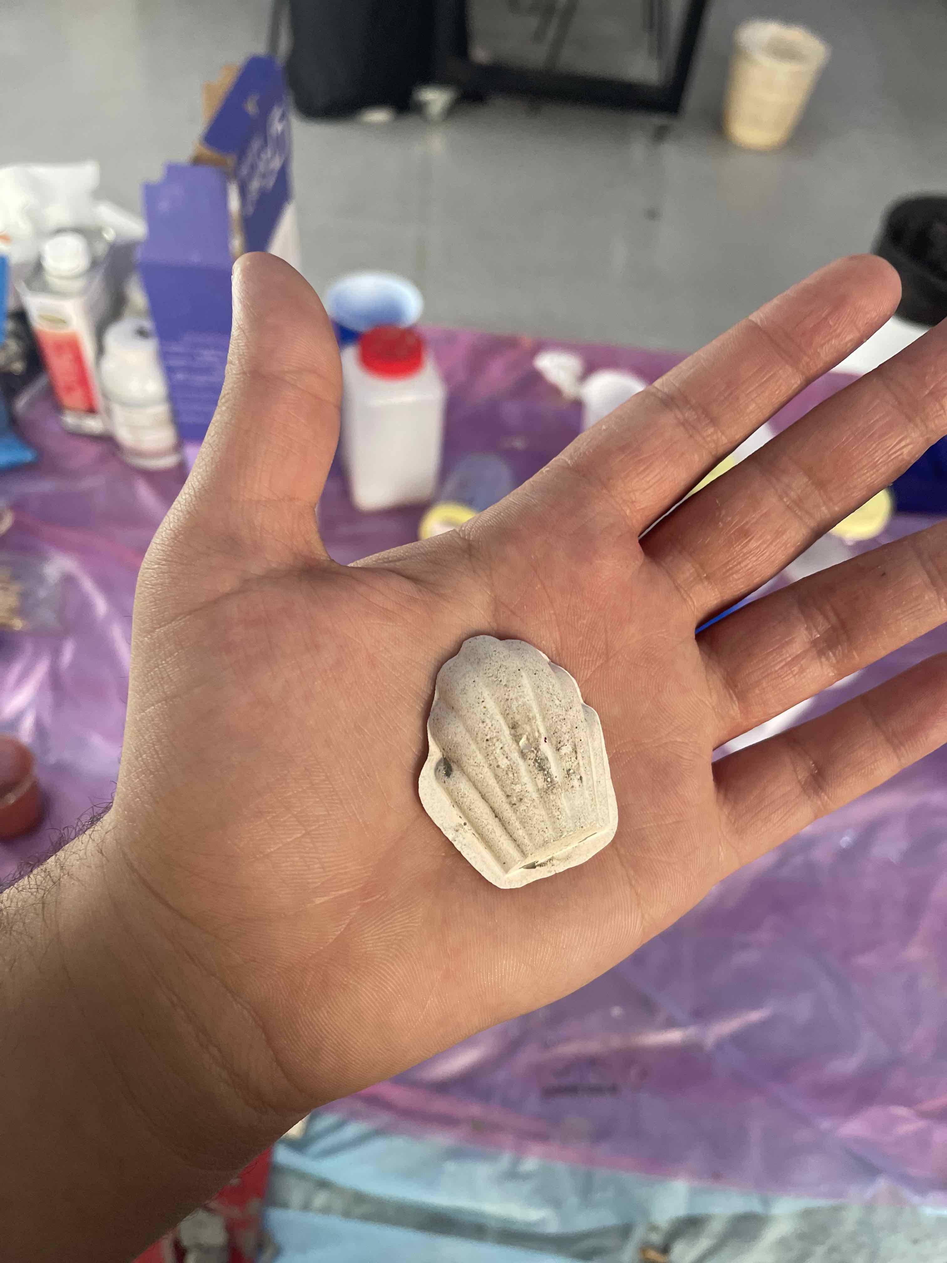
Final Results
It was had a abit of black spos on tiop of it, as i forgot to clean the mold before pouring in my mixture.
Individual Assignment
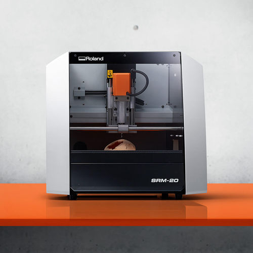
Miling Machine
A milling machine removes material from a work piece by rotating a cutting tool (cutter) and moving it into the work piece. Milling machines, either vertical or hori- zontal, are usually used to machine flat and irregularly shaped surfaces and can be used to drill, bore, and cut gears, threads, and slots.
Milling Process
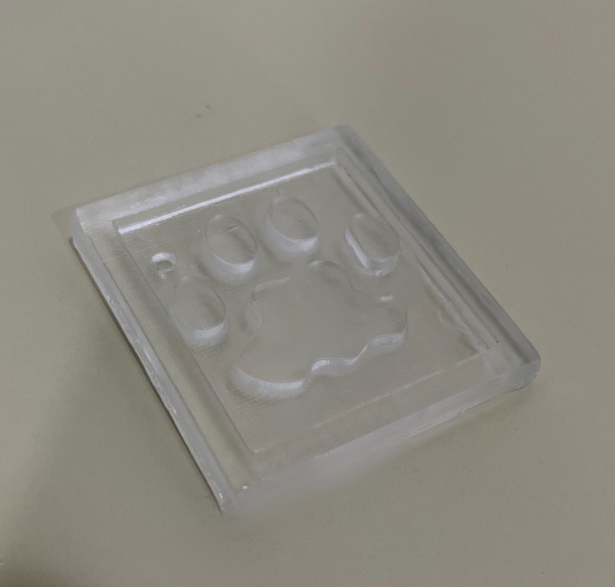
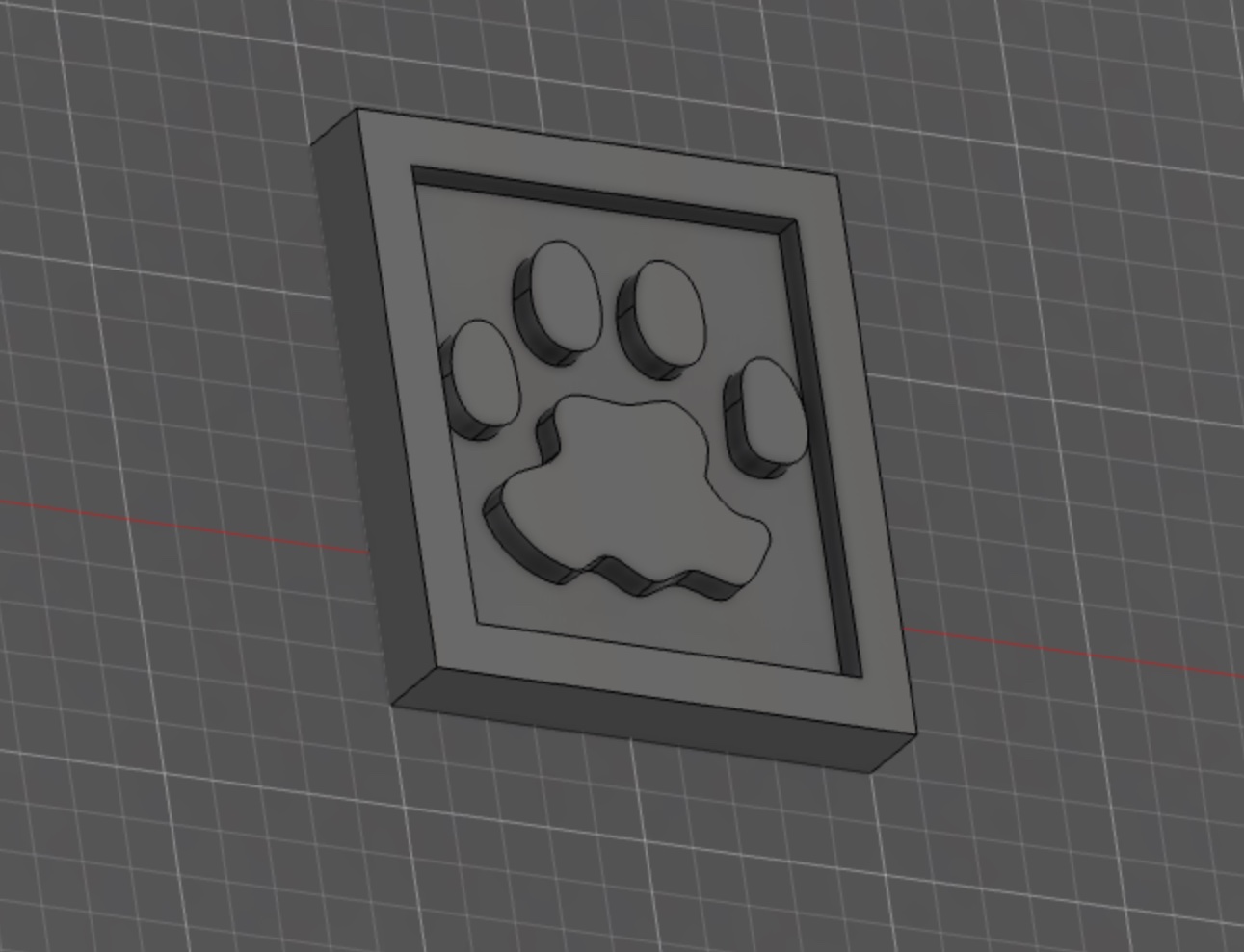
For the moudling process, where i had to create a cavity for the design I wanted, I first created a plate, extruded it to the size I wanted, and then placed a SVG file on the plate and extruded that too.
To look somehting like this
 First on the plate we were cutting into, we added double sided tape to the back of the plate, inorder to place it on the Milling machine bed and so it doesent move while cutting.
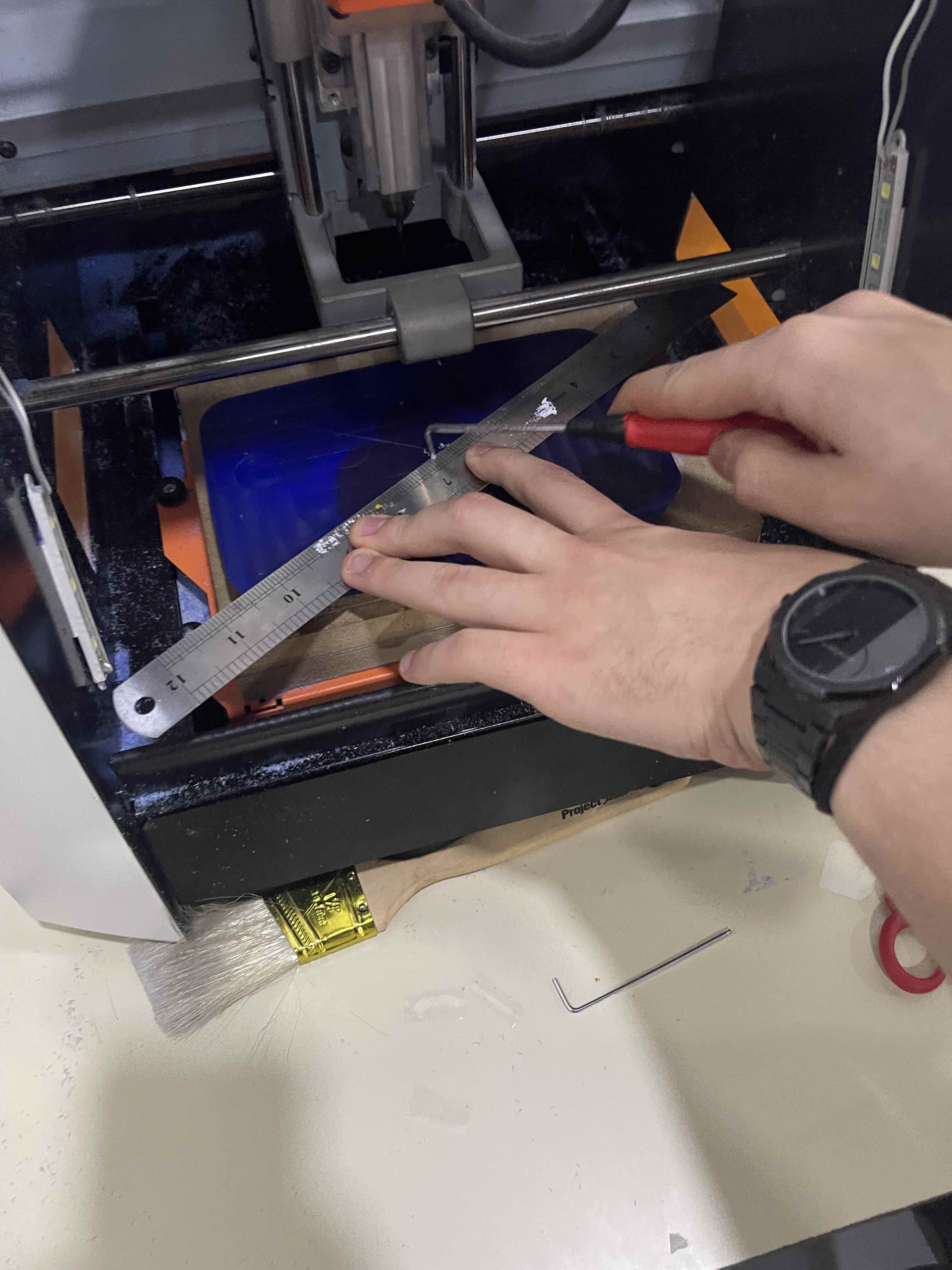
Below is an image of the marking the exact orgin of the plate to able to use it as a guid when position the axis of the Millig machine pin.
First on the plate we were cutting into, we added double sided tape to the back of the plate, inorder to place it on the Milling machine bed and so it doesent move while cutting.
Below is an image of the marking the exact orgin of the plate to able to use it as a guid when position the axis of the Millig machine pin.
I then sent it to Smashing Robo-Albar, the software that was used to edit the settings of the miling machine before cutting.
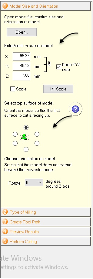
Using the Smashing Rob-Ablar software, under Model size and Oreintation I set up the exact axis of the the plastic block that is i will be using for cutting.
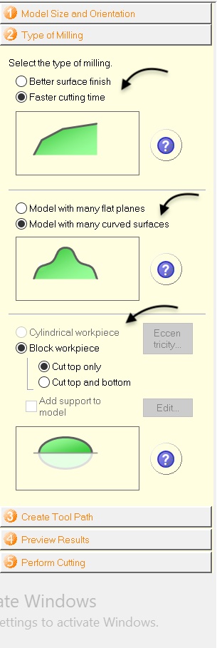
 Under Type of Milling, I selected a faster time milling, and chose Milling with curved surfaces as pasrt of my design had curves, I then chose Block piece since I’m working with a plastic block, and chose to cut only from the top part of the plastic block.
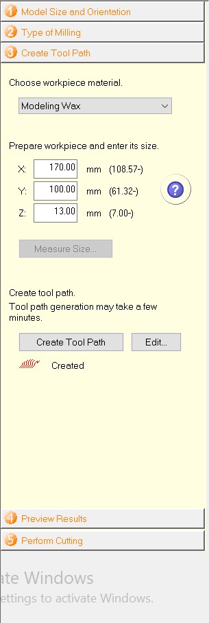
 Under Create Toolpath i set yp the axis of the toolpath or the milling(roughing) pin to the be placed on the origin of the plastic block that I’ve arked earlier.
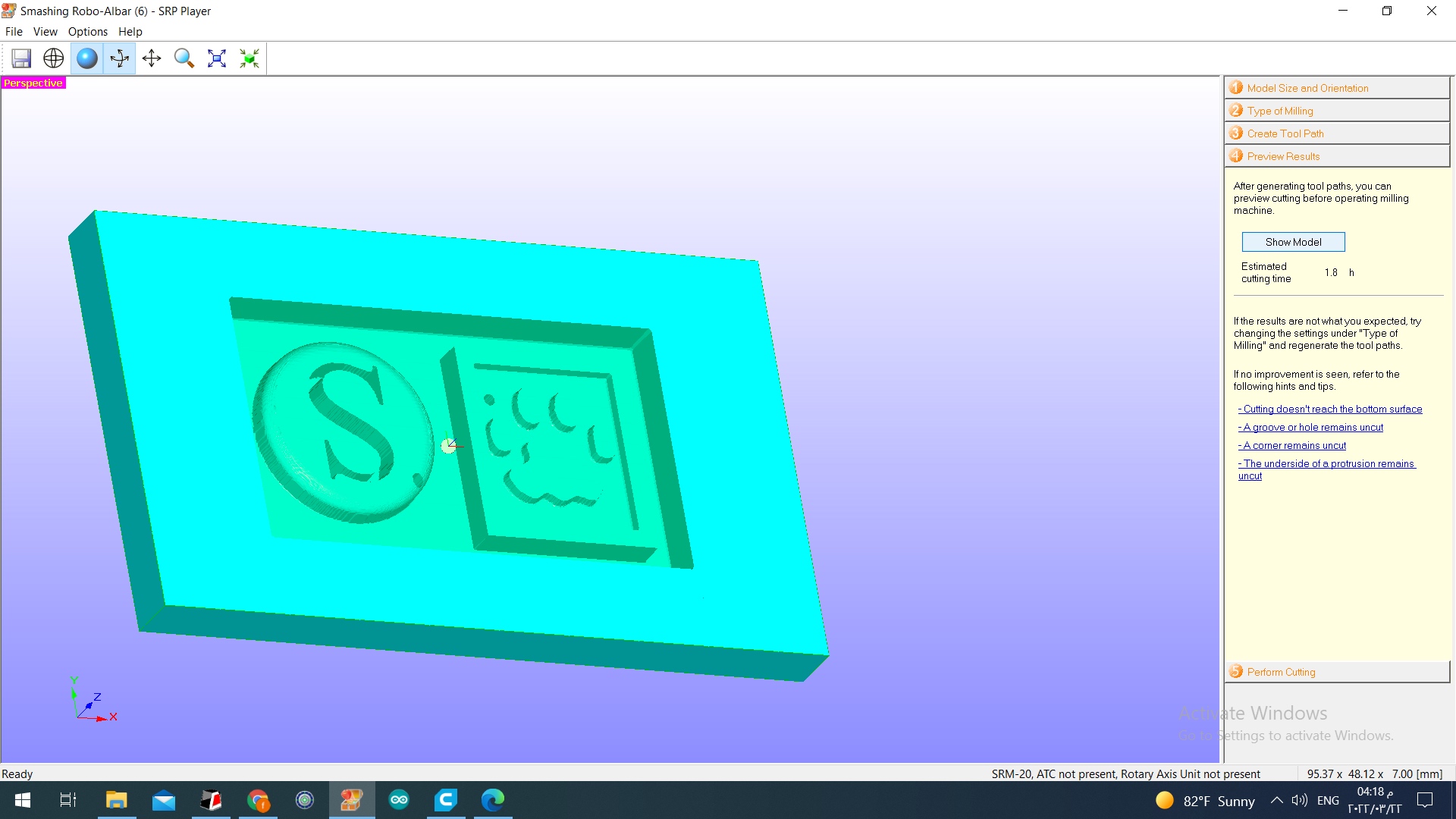
 Under Preview Results I clicked Show Model which showed a preview of hwo the block will turn out after cutting.
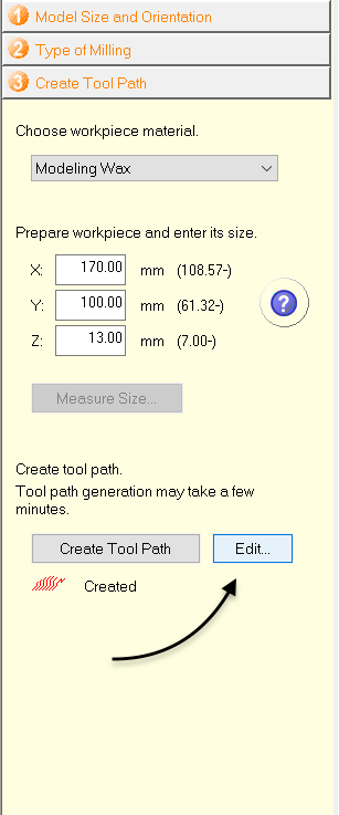
 After that, under Create Toolpath I clicked on Edit
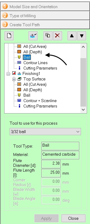
 Next, under Roughing I chose the Ball and under Tool used for this process I chose 3/32 Ball
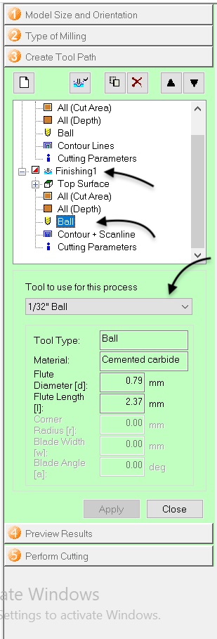
 After that, under Finishing, I set the exact same setting as for Roughing
What is the difference between Roughing and Finishing?
Roughing is mainly to remove a large amount of excess material from the piece, finishing is to improve surface finish, tolerance, and reduce or minimize the errors.
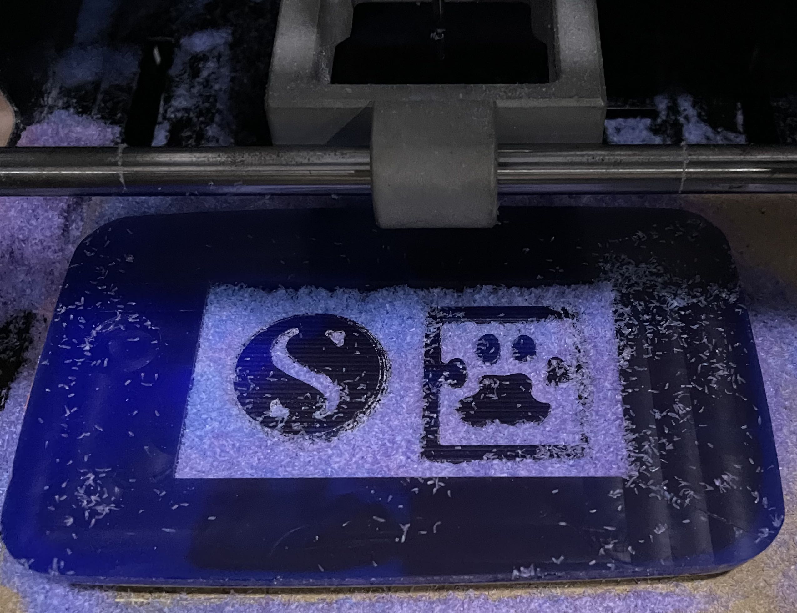
Below is an image of the plastic block after finishing the roughinh stage, it usually cuts larger pieces and isnt smooth.
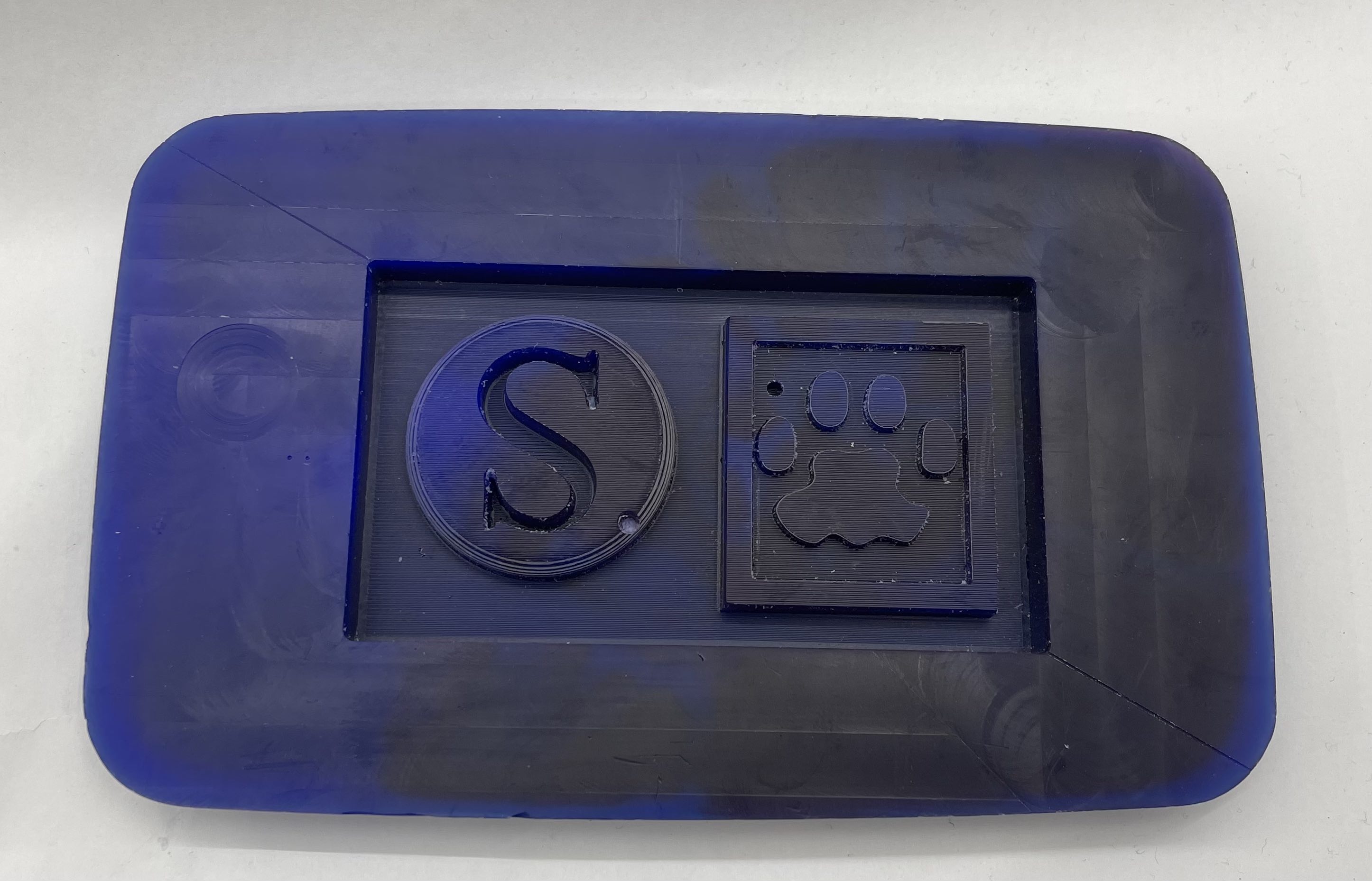
 Below is an image of the plastic block after the finishing the Finishing process, which made come out smooth and ready to be applied in the moulding process.
 </br
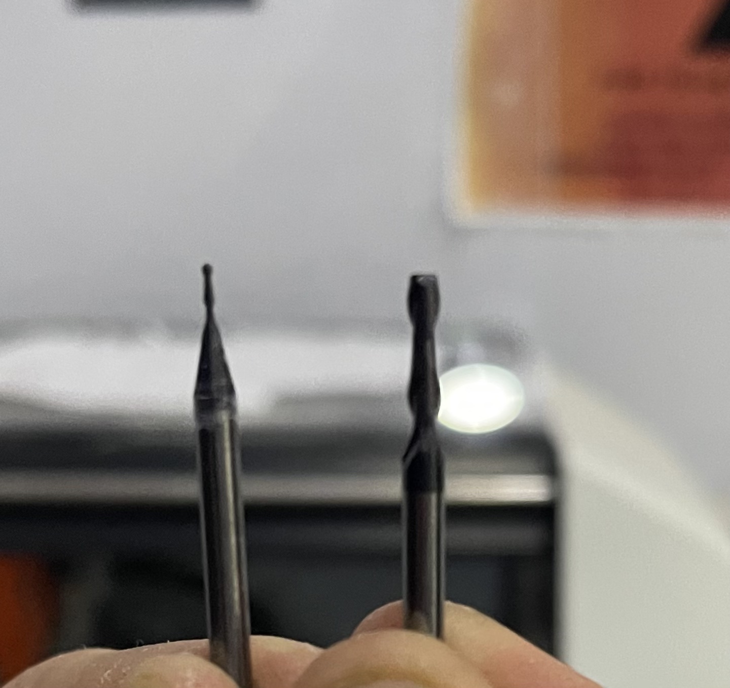
In this image, you can see the difference between a roughing pin (on the right) and a finishing pin (on the left).
</br
In this image, you can see the difference between a roughing pin (on the right) and a finishing pin (on the left).
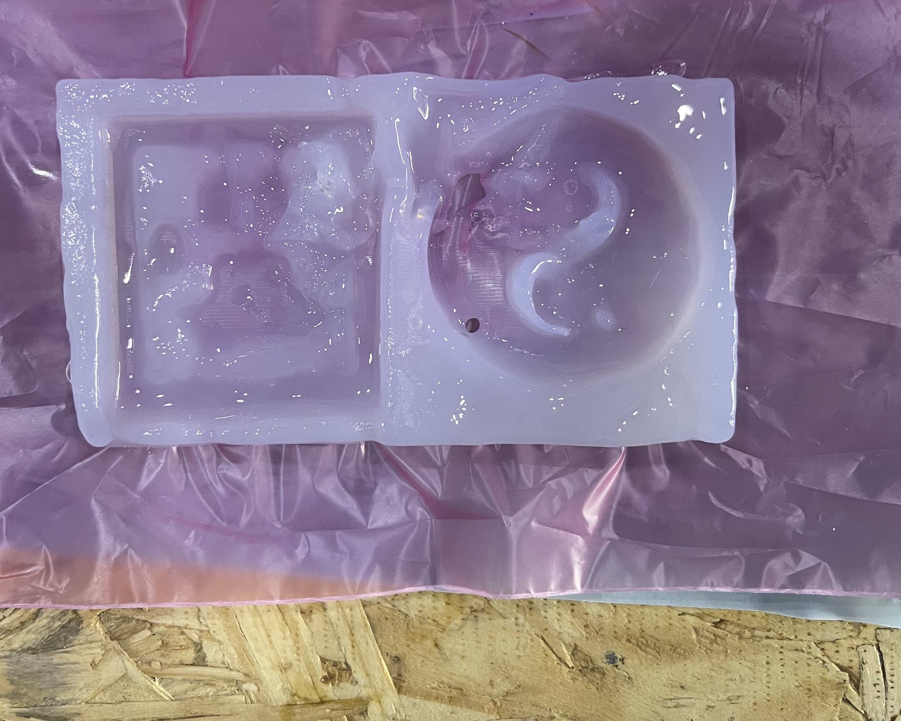
Moulding Process
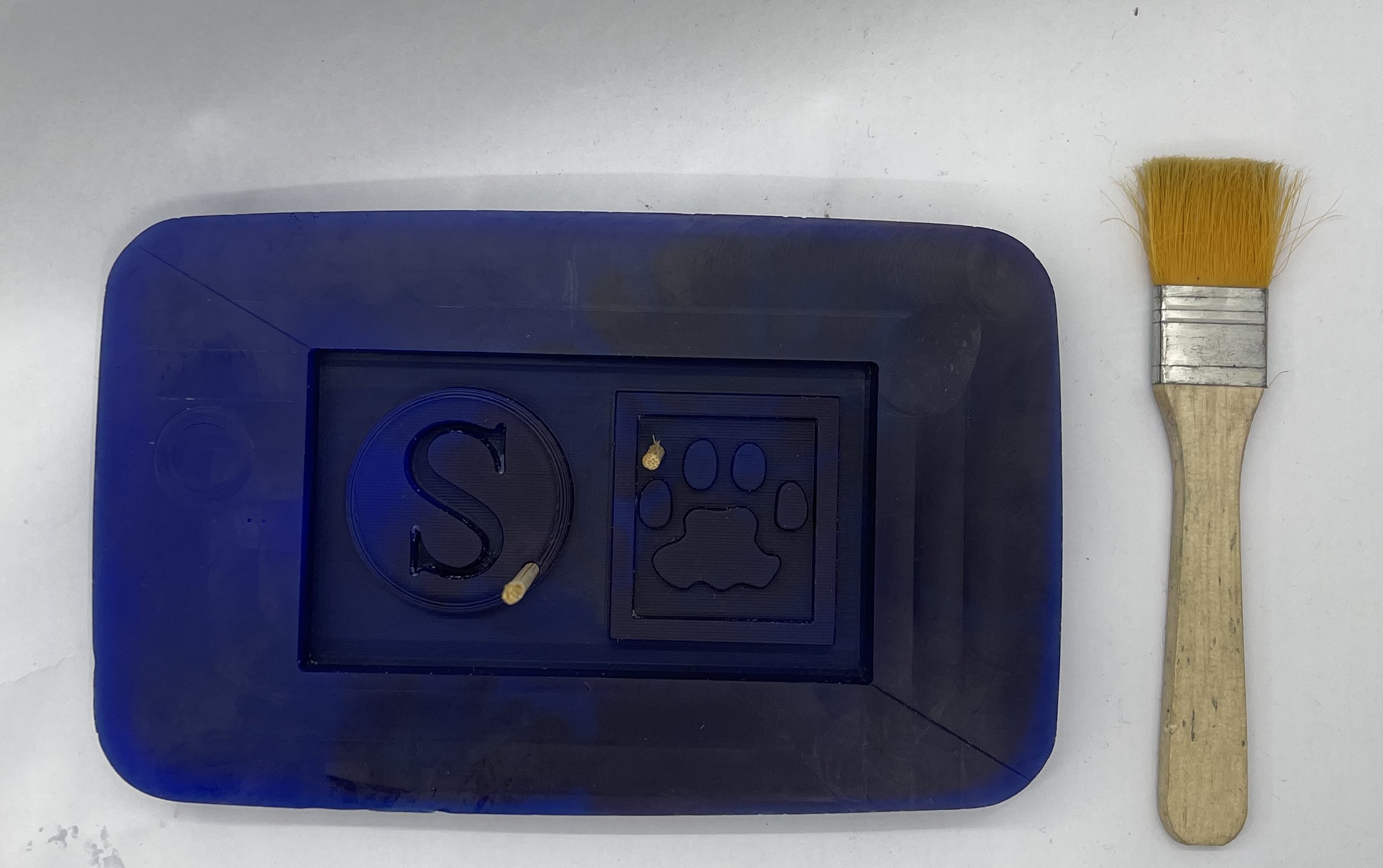
After completing, I brushed down the plastic block to eliminate any finishing residue. I also inserted sticks where I didn’t want the silicon that I was pouring in to form a mould to enter, so that there would be a hole for me to insert a medal.
 When it came to measuring how much silicon I’d be using, I filled a cup with water, poured it into the plastic block until it was full, drained any excess water in the cup, then repoured it into the cup before weighing it with a kitchen scale which turned out to be aroud 50g (excluding the cup weight). Now that I had this info, I took the silicon combination (A and B), which is two parts: silicon and the hardening ingredient, measured 25g of each, and carefully mixed them together (it is essential to prevent bubbles in this procedure). I then left to dry for atleast 2 hours before attempting to take out the hardened silicon.
In this video below you can see a step by step on how I created the mould.
When it came to measuring how much silicon I’d be using, I filled a cup with water, poured it into the plastic block until it was full, drained any excess water in the cup, then repoured it into the cup before weighing it with a kitchen scale which turned out to be aroud 50g (excluding the cup weight). Now that I had this info, I took the silicon combination (A and B), which is two parts: silicon and the hardening ingredient, measured 25g of each, and carefully mixed them together (it is essential to prevent bubbles in this procedure). I then left to dry for atleast 2 hours before attempting to take out the hardened silicon.
In this video below you can see a step by step on how I created the mould.
However, it was a failed attempt, so I left for an extra few hours, yet it didnt harden fully. as you can see in the image below.
 Now that I know that it failed, after some investigation, turns out I didnt mix the two parts of silicon the recomended amount of time, so I had to redo the whole process again, carefully this time, making sure every step is taken into consideration. Also, removing the sticks, as it turns out that it was undeeded.
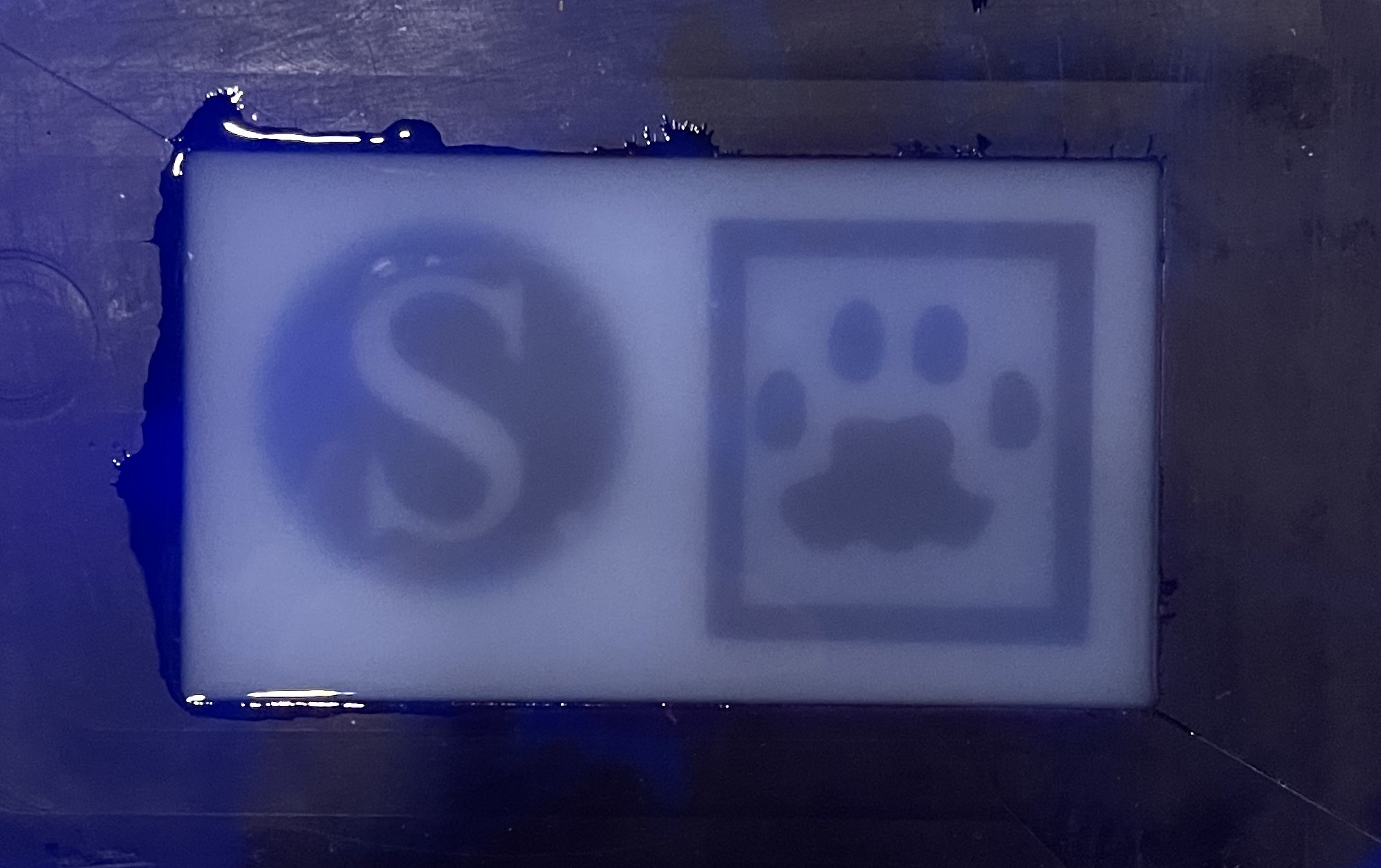
Final Results
 Click here to download the STL file
Casting
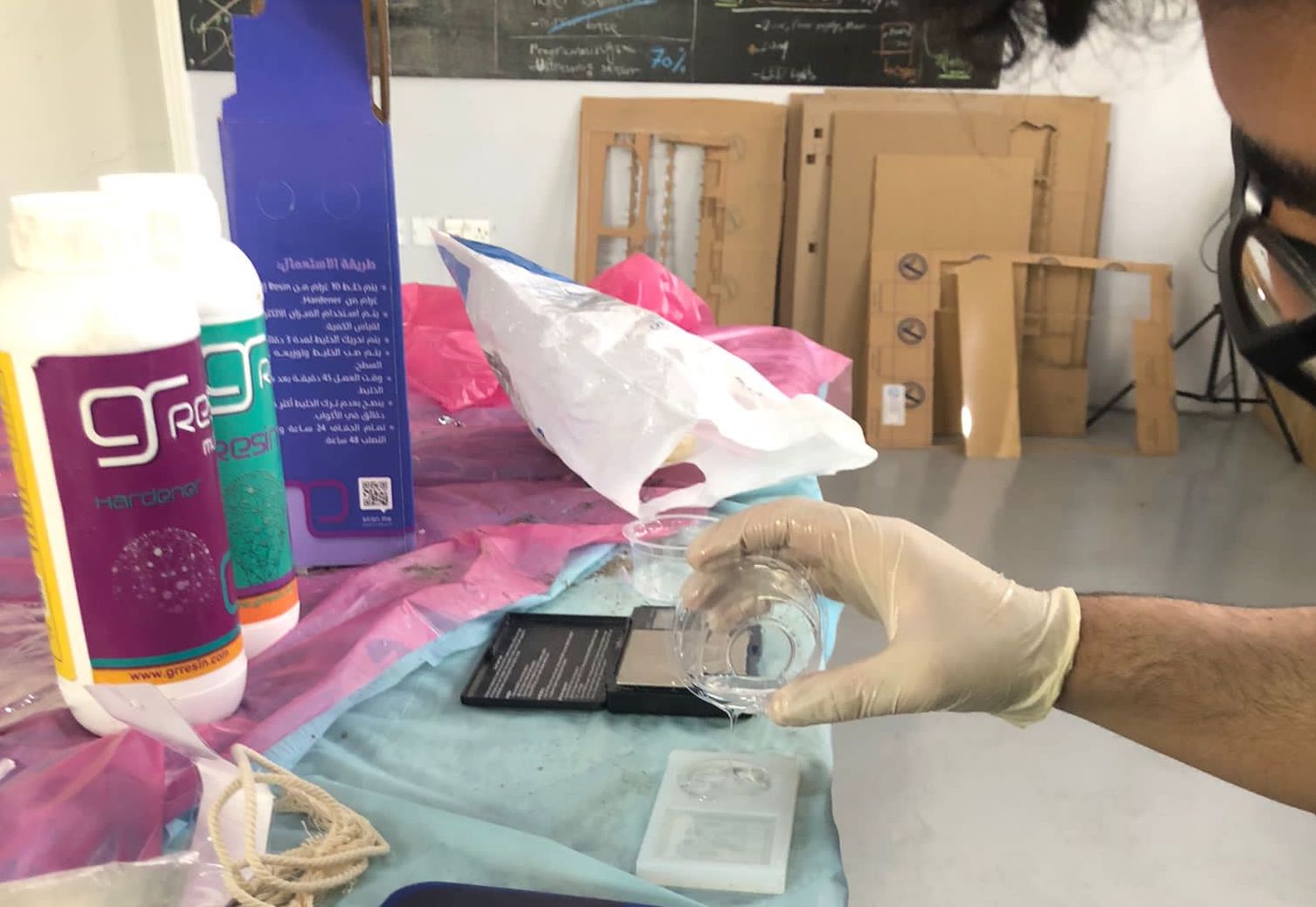
For the casting part i chose to use Resin as the material for my mould.
First of all, I grabbed the resin which was a two part process the resin and the hardening liquid to create a hard solid object.
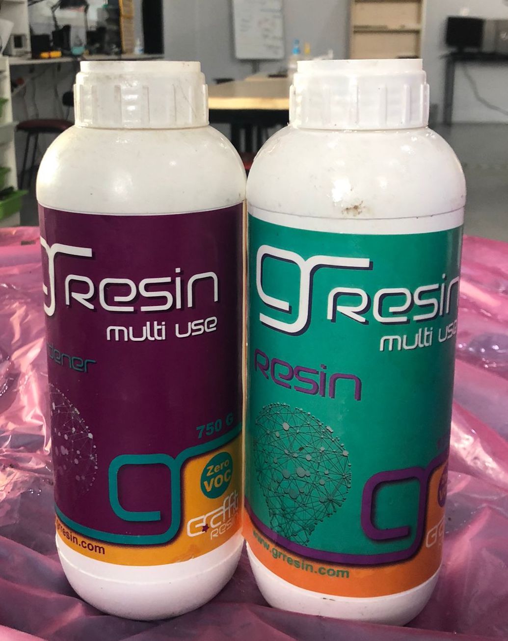 I combined two parts resin with one part hardener in a 2:1 ratio, stirred it thoroughly for approximately 5 minutes to ensure no bubbles formed in my concoction, then poured it into my silicon mould that I had previously created. Even though I tried to remove all of the bubbles after pouring it, there were still some, so I had to apply heat to the entire mould for it to climb up and be removed from the mixture.
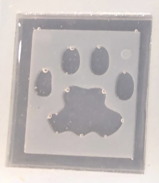
 Here you can see the bubbles that was formed after pouring the mixture.
Final Results