3. Computer controlled cutting
This week, I learnt how to operate two types of computer-controlled cutting machines: a vinyl cutter and a laser cutter.
Vinyl Cutter
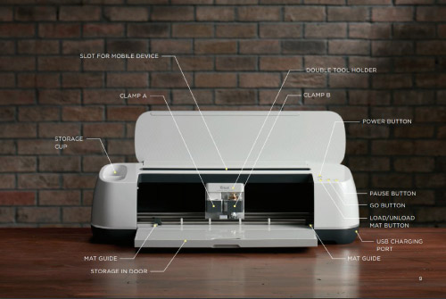
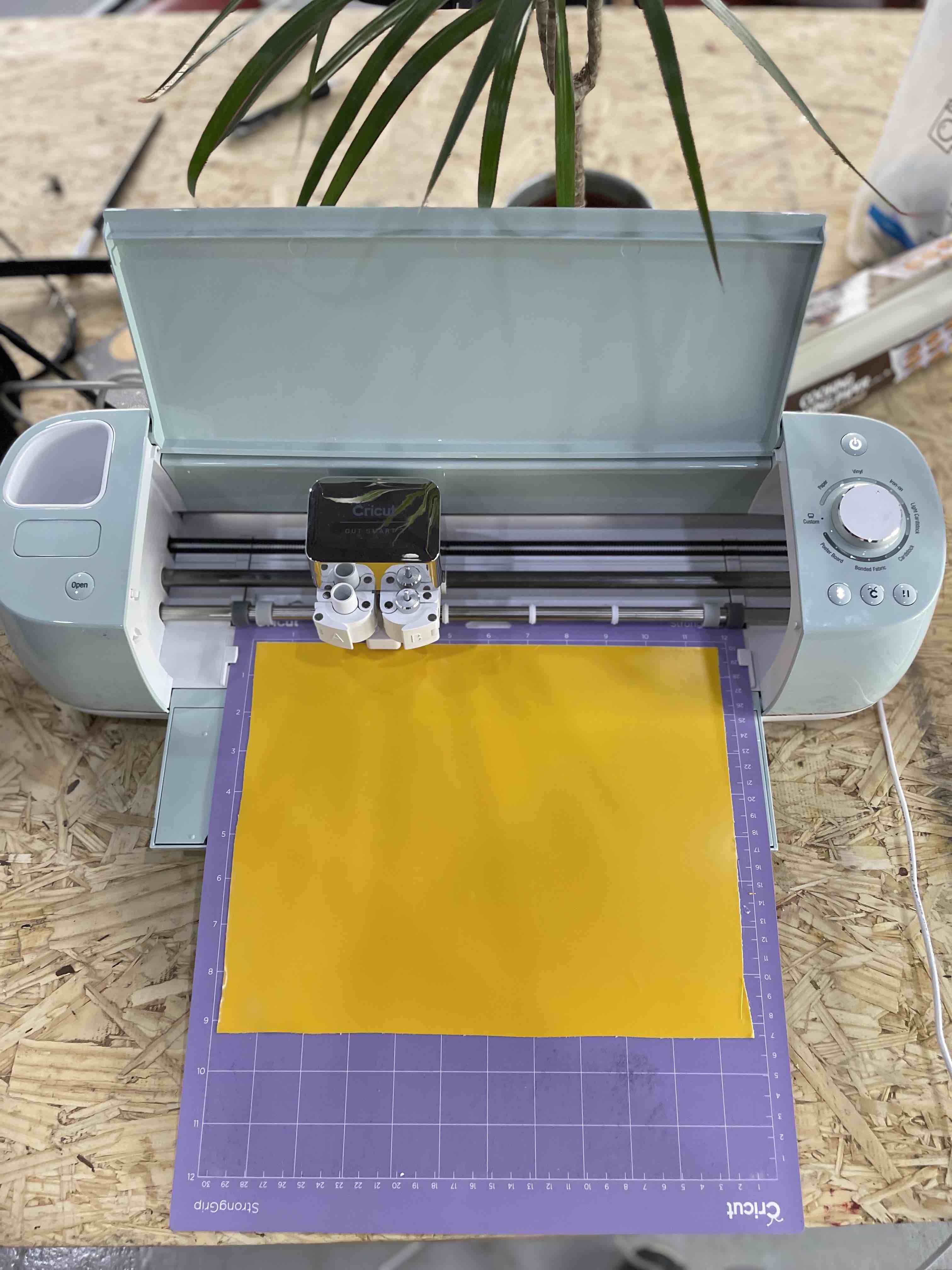
A vinyl cutter is a low-cost sign-making machine. Vector files with patterns and letters created on a computer are immediately cut on a roll of vinyl that is mounted and supplied into the vinyl cutter through a USB or serial cable. Signs, banners, and stickers (which i made using this machine) are the most common uses for vinyl cutters. Although these machines were meant to cut vinyl, they can also cut computer and speciality papers, as well as bulkier things like as thin sheets of magnet. The Vinyl cutter I used was a Cricut explore 3.
The Machine is seen here, along with all of its components.
Safety Measures
- You are not permitted to leave a computer running unattended.
- Using liquids, metals, or combustible materials within the cutter is strictly prohibited.
- While a work is in progress, you must not leave the vinyl cutter unattended.
- While the work is in progress, you must not place your hands or other items in the path of the cutting arm.
- Don’t to lean on the machine.
- Don’t wear ties, belts, or leave your hair down while the cutting arm is in use.
- You are not pemitted to stop the machine while it is in use.
- While the machine is turned on, do not move the cutting head.
How to use a Vinyl Cutter.
- First, I downloaded Circut, a software made by the creator of the machine, that I used to upload and modify my image.
- Second, I searched the internet for an image to utilize to produce a sticker using the Vinyl cutter,Then I downloaded the photograph from the internet to my laptop. Next, I launched Cricut app to begin the procedure. I initially created an account via which I may store my projects to the cloud and access them from any computer.
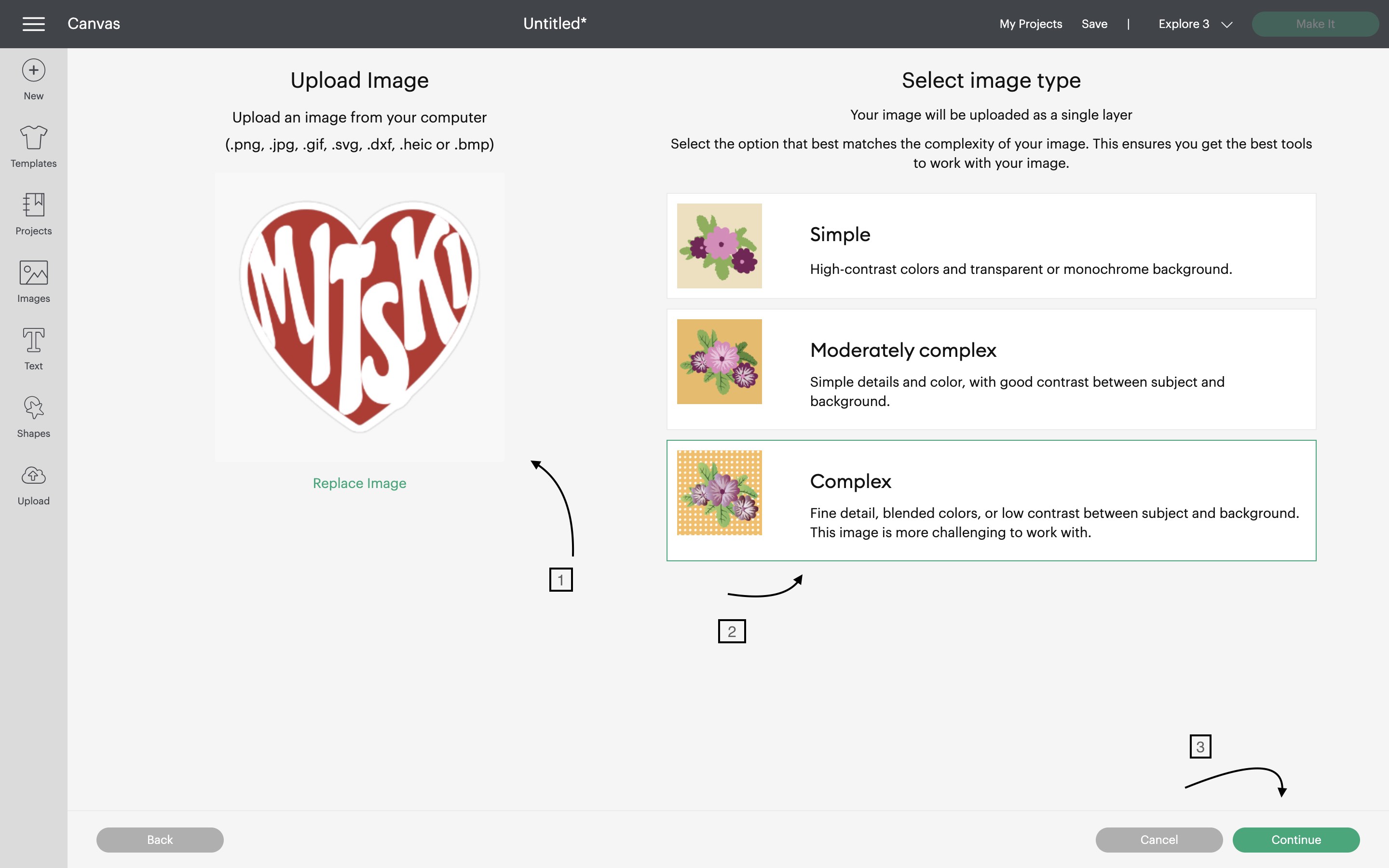
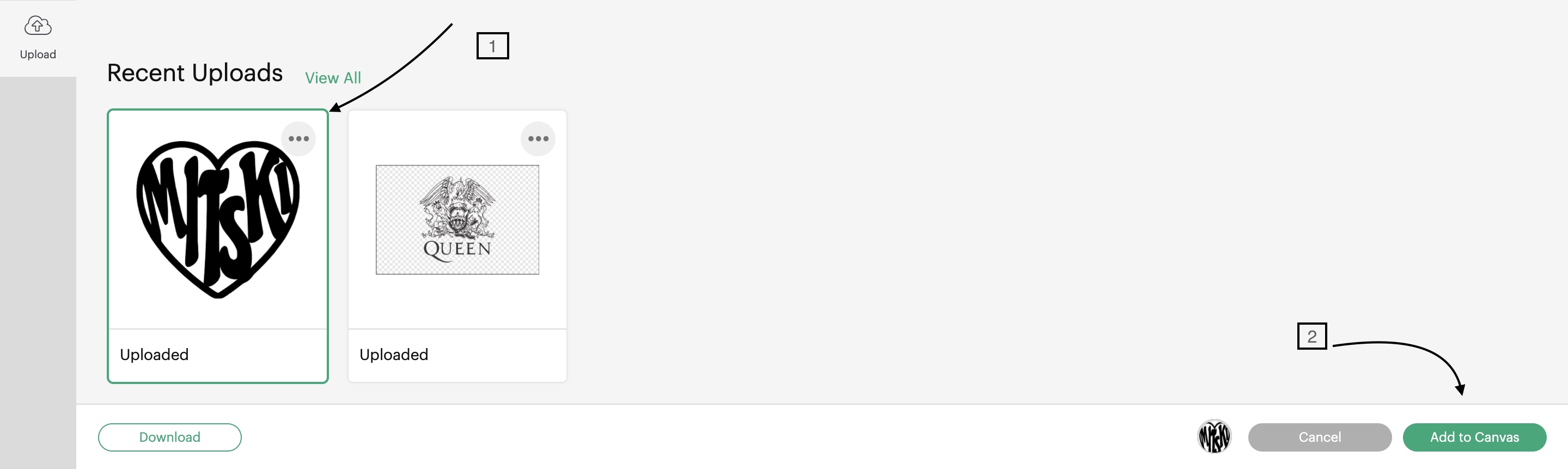
- Third, I clicked on New Project and moved to the right panel and clicked on Upload, after uploading my image, I chose the complex option, so the sticker will turn out more detailed, and then clicked on continue.
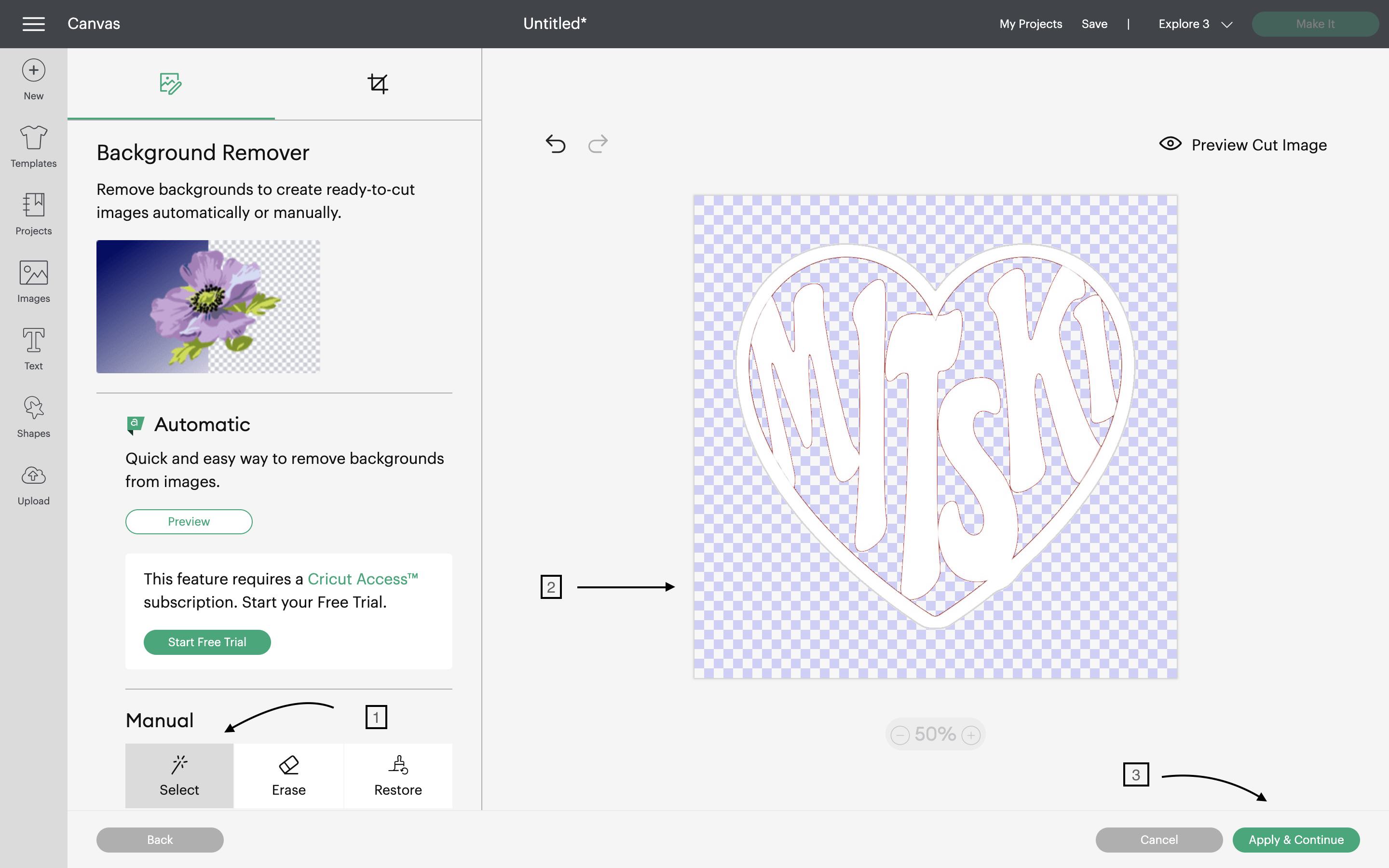
After navigating to the following screen, where I could select to make the picture background transparent, I first clicked on Manual> Select, then I clicked on the background portions I wanted to make transparent, double-checked everything by clicking Preview cut image, and finally clicked Apply and continue.
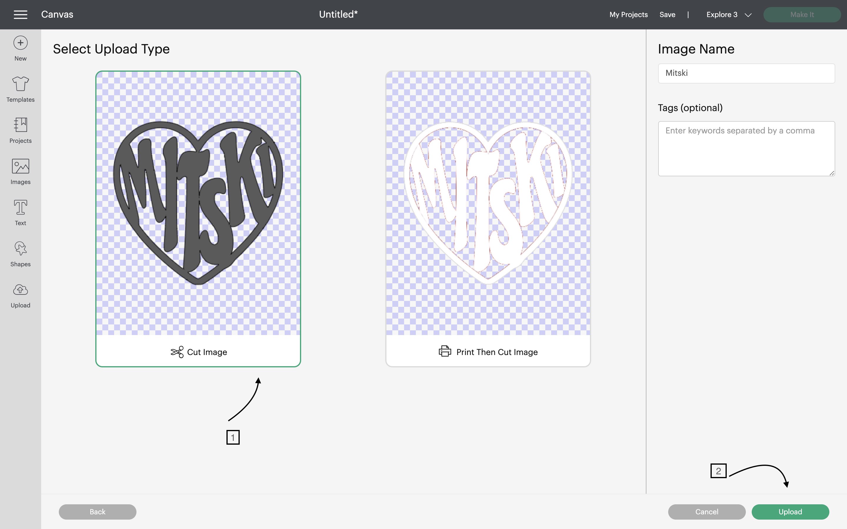
On the next page I selected cut image> continue.
On the next page I chose the picture I selected the picture> Add to canvas where I can modify it.
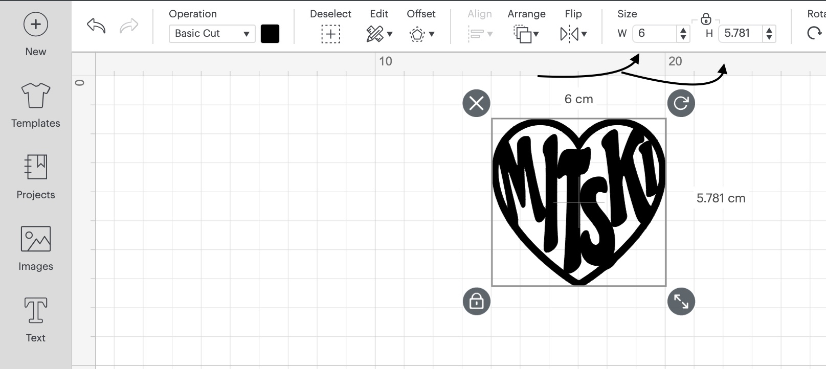
- Now that I can view it on the canvas I changed its width and height to get the exact measurement I want.
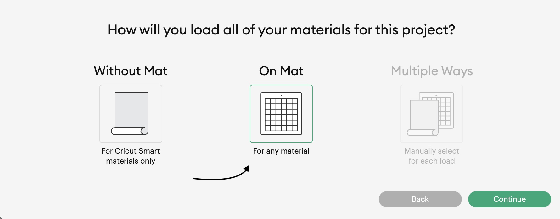
Next I clicked on Make project> On Mat> Continue
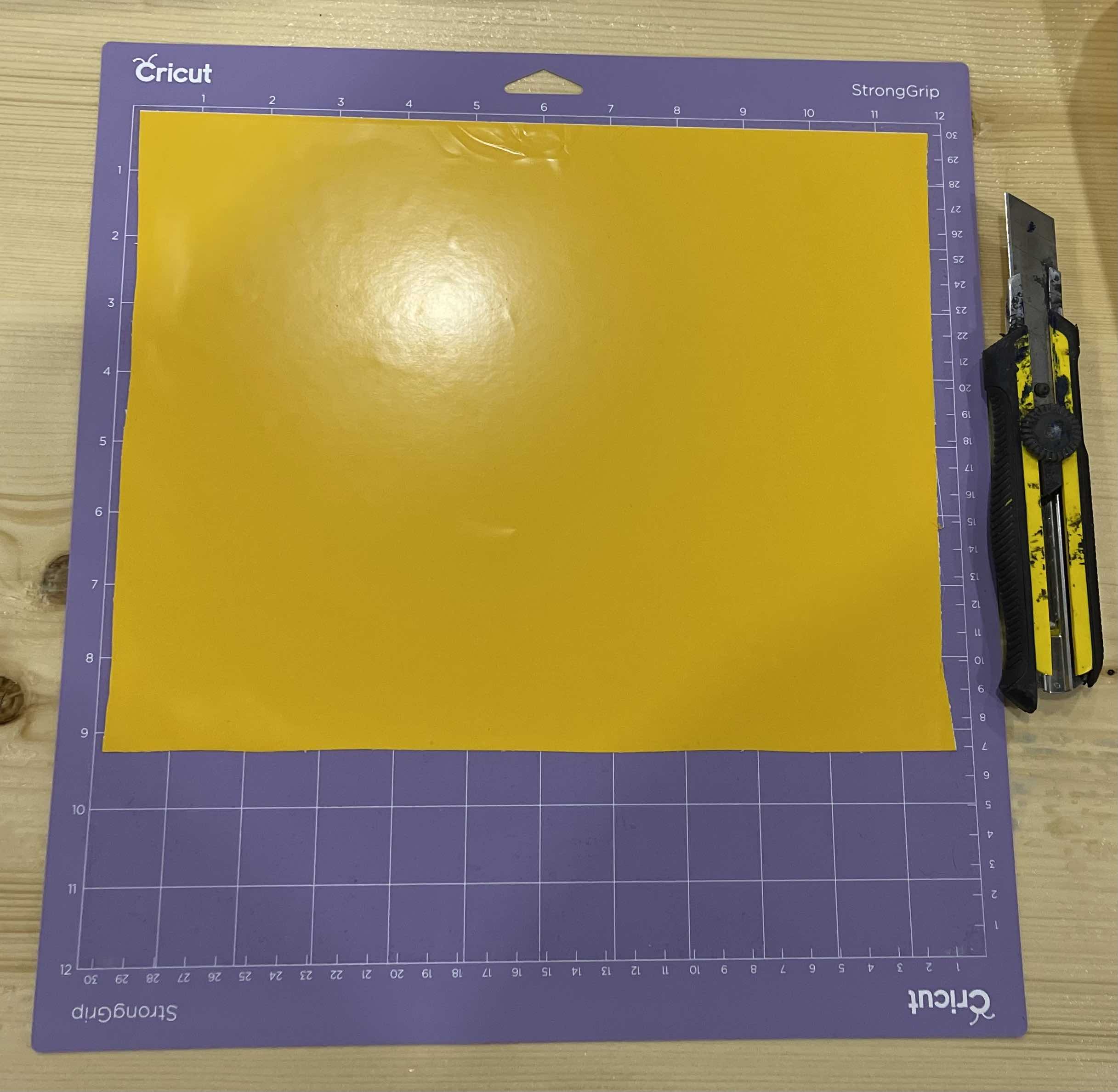
- Now I placed the vinyl on the mat.
In the machine, I placed the mat between the mat guide that are placed on the opposite side inside of the machine.
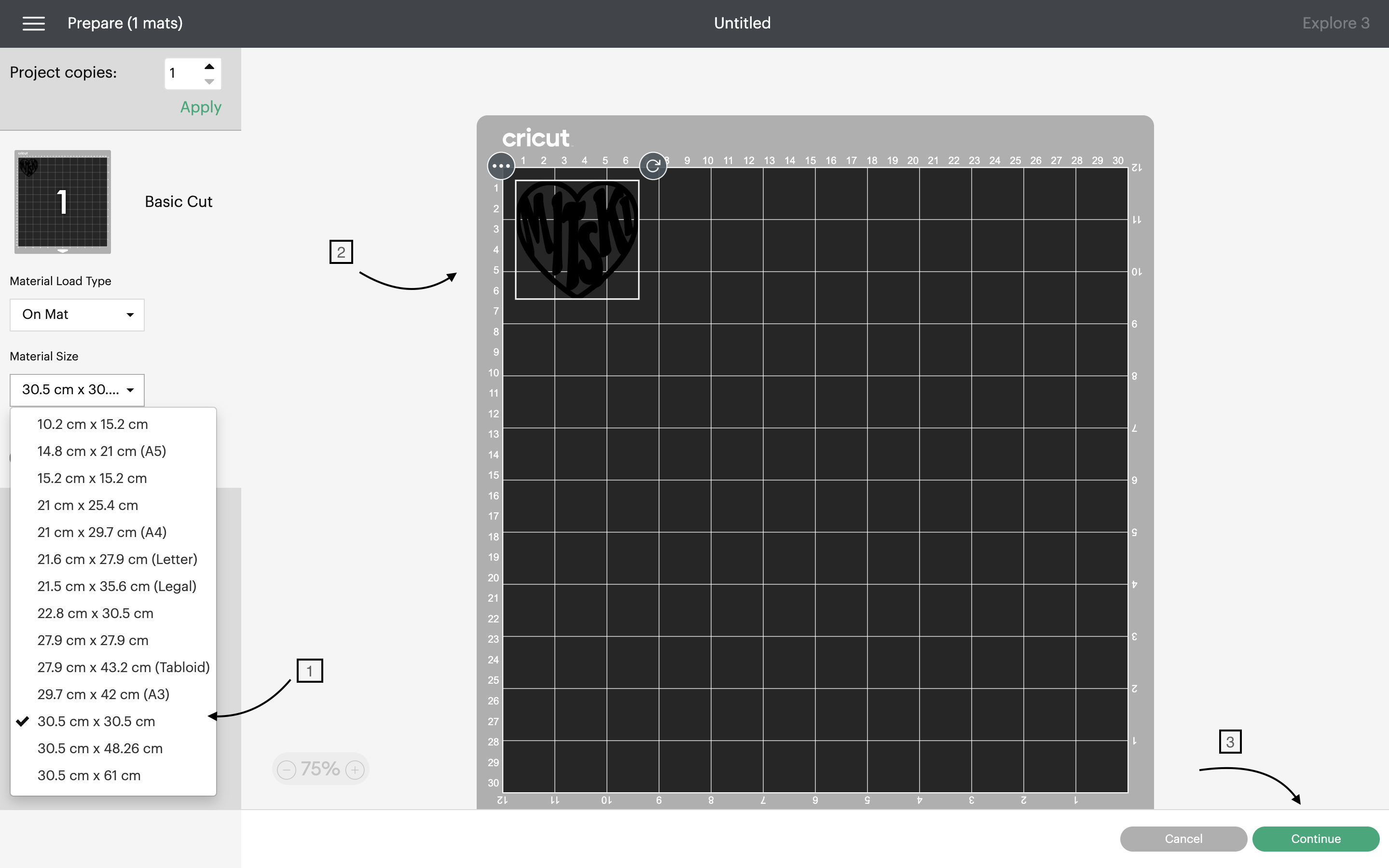
Here, I double-checked that the material was the correct size (as shown in the image below), positioned the image on the mat, and then clicked on continue.
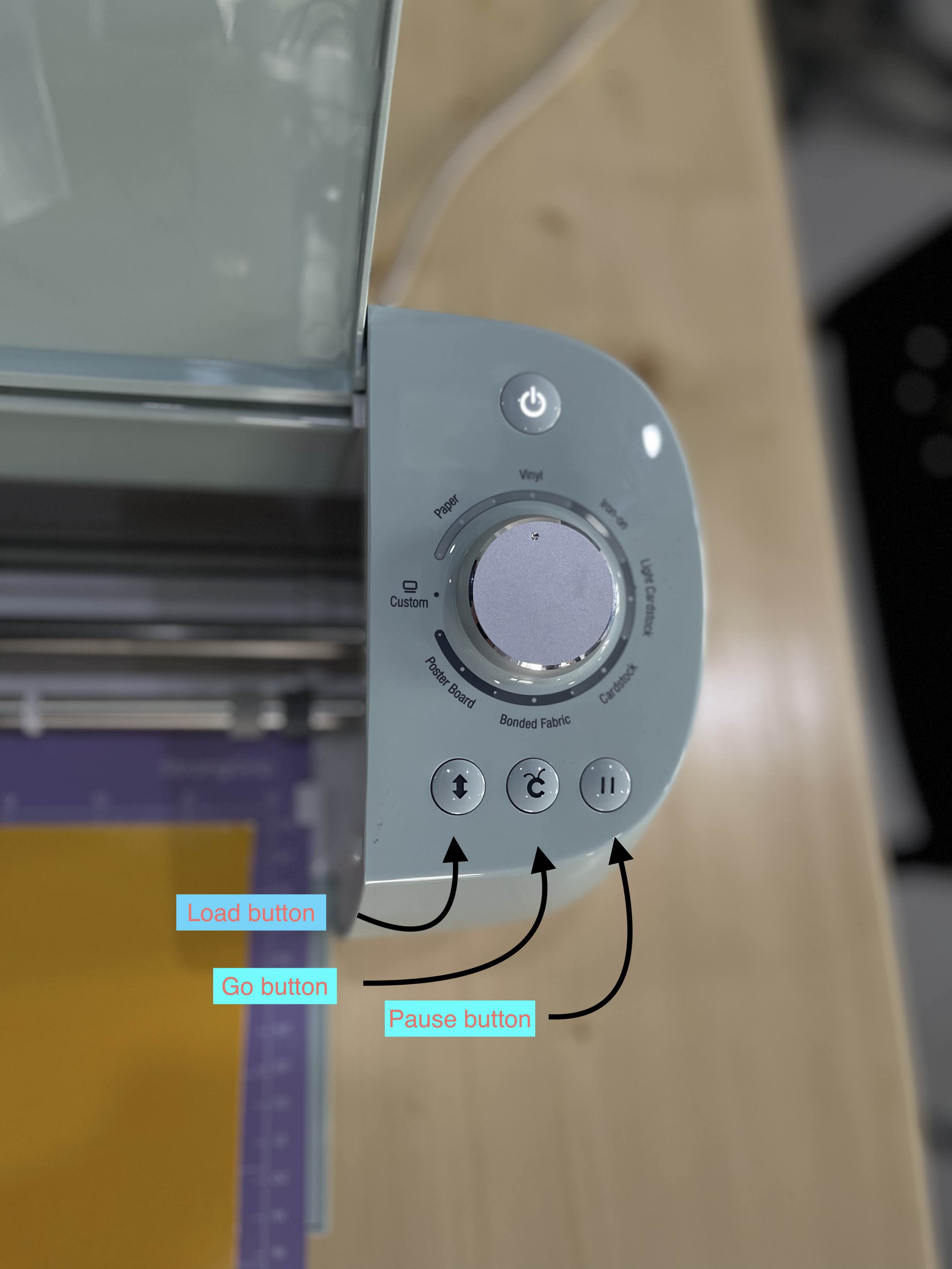
Then, using the machine, I pressed the double-sided arrow (Load button), and the mat was inserted into the machine. Then I pressed the button next to it (Go button), which began the cutting process.
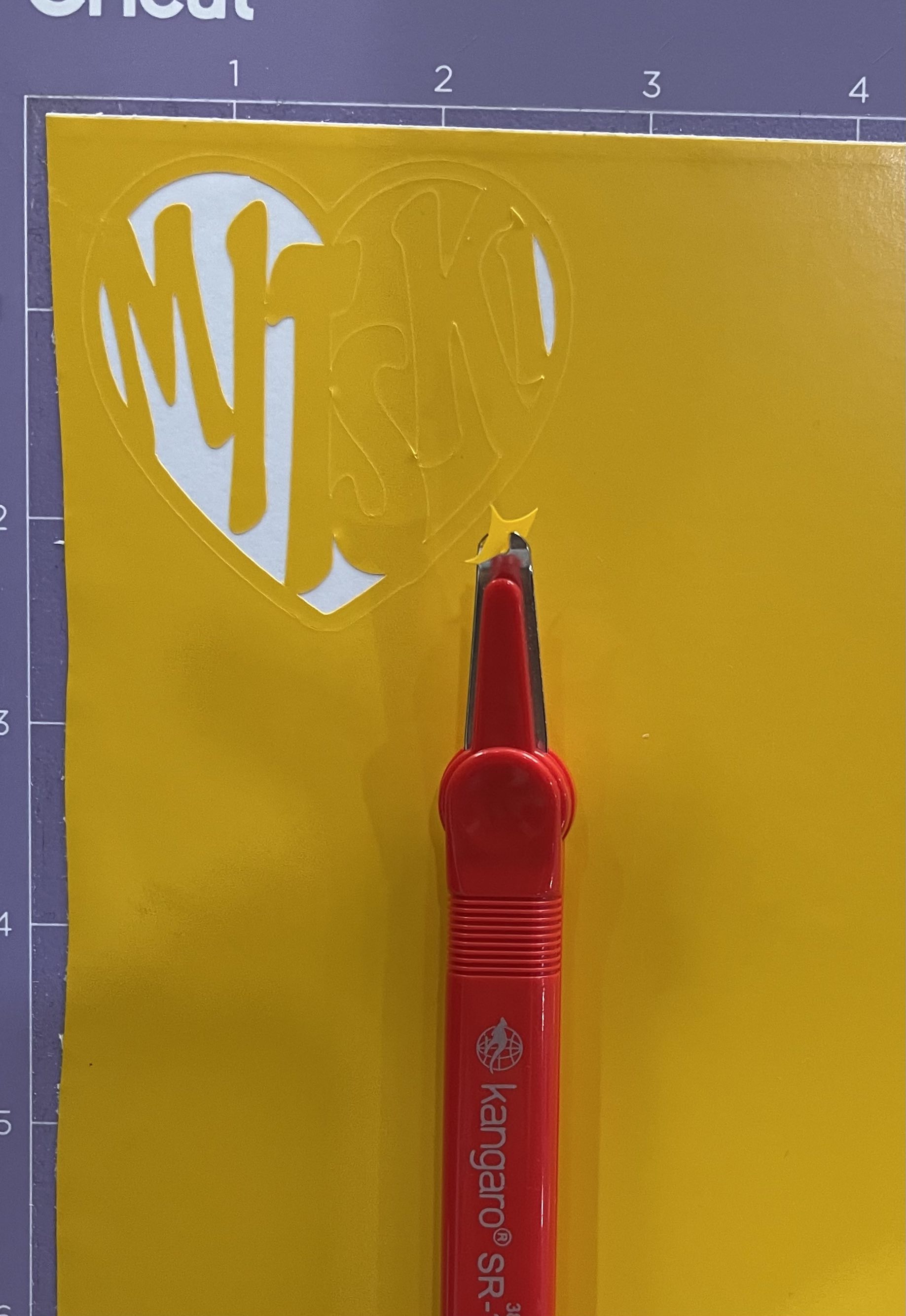
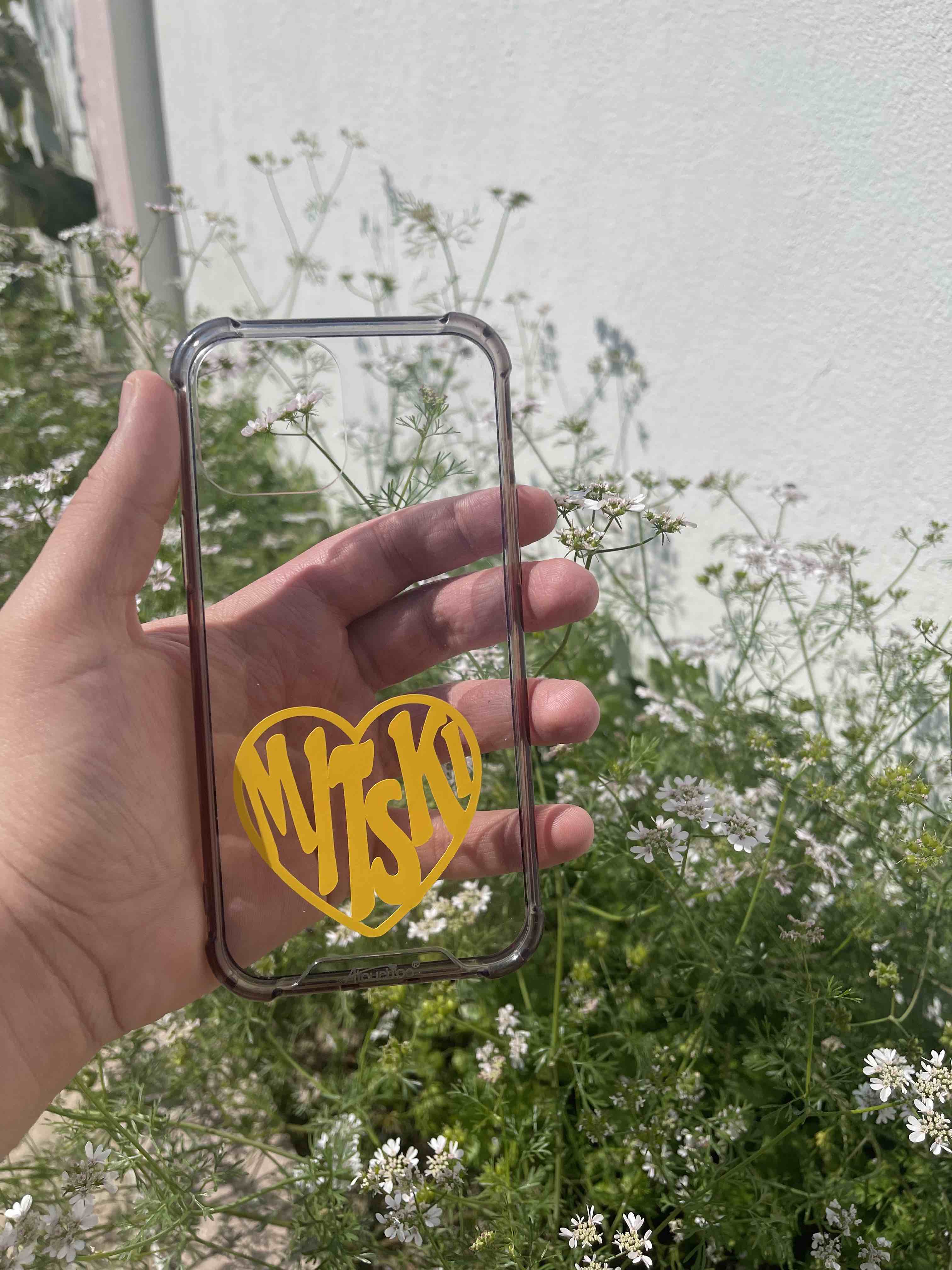
Then using a lifting tool, i lifted the unwanted pieces of sticker from the vinyl, and lifted the main sticker careffully as it was dilacet and placed it on my phone cover.
Final Results
Click here to download the file
Mitski Heart Logo Sticker Poster, Designed by Nicolepee.
Laser Cutter
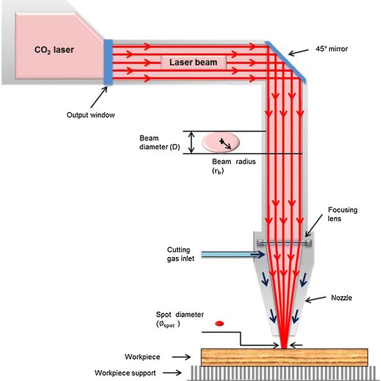
Laser cutting is essentially a manufacturing method that employs a narrow, concentrated laser beam to cut and etch materials into specific designs, patterns, and forms defined by a designer. This non-contact, thermal-based production technology works well with a variety of materials, including wood, glass, paper, metal, plastic, and gemstone. It can also produce complicated pieces without the use of a custom-designed tool.
Below are the components of the Laser beam which is used to cut the materials precisely.
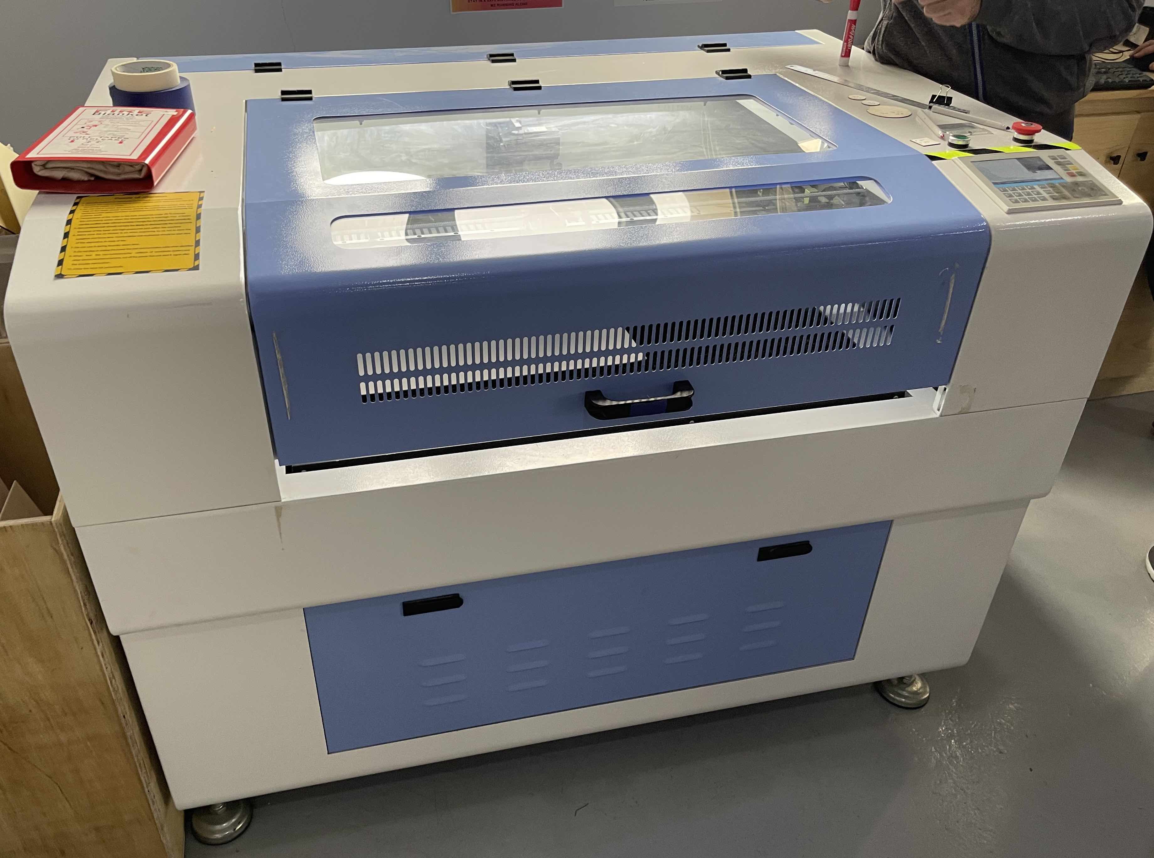
In this image is the laser cutter we used.
Safety Measures
- Operators should not be absent while the machine is running in the case of fire. Check the submerged pump when started each time,do not use it if the pump yields no water.
- Do not use it unless the machine is in grounding connection.The earth wire of the laser power sowrce should be connected not to doors and windows, water pipes and other installations,but to the ground especially the. outdoor earth.
- Temperature of the water in the tank should be under 25°C. Changethe circulating water when the temperature is overhigh. You’d better use the purified water without sundres Change the circulating water periodically.
- Non-professionals should not take the liberty to disassemble the components because of the laser and high-pressured part within the machine.
- Make sure the air blower is on when engraving so as not to stain the eyeglass and focus lens. Combustibles and explosives shoyld be kept clear of the apparatus in case of fire.
- Do not use it during thunder storm time.
- Do not plug or unplug the power line and communication cable when electrified.
- When find the non-luminance. the collision of coordinate system and other abnormal phenomenons, cut off the power first and start it again after the trouble elimination.
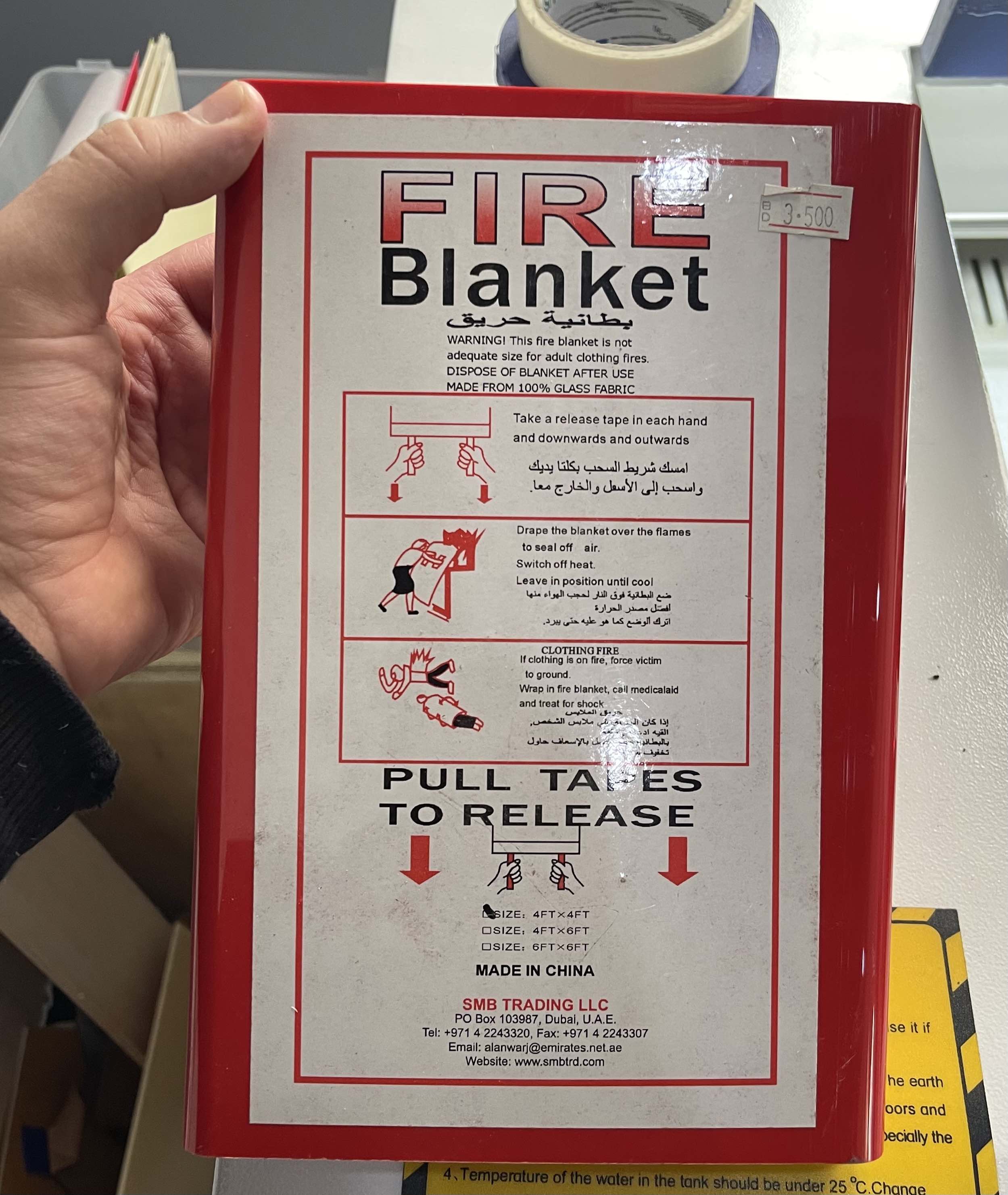
In the event of an emergency, the fire blanket seen below can be used to extinguish the flames. It is always placed next to the machine.
Group Assignment
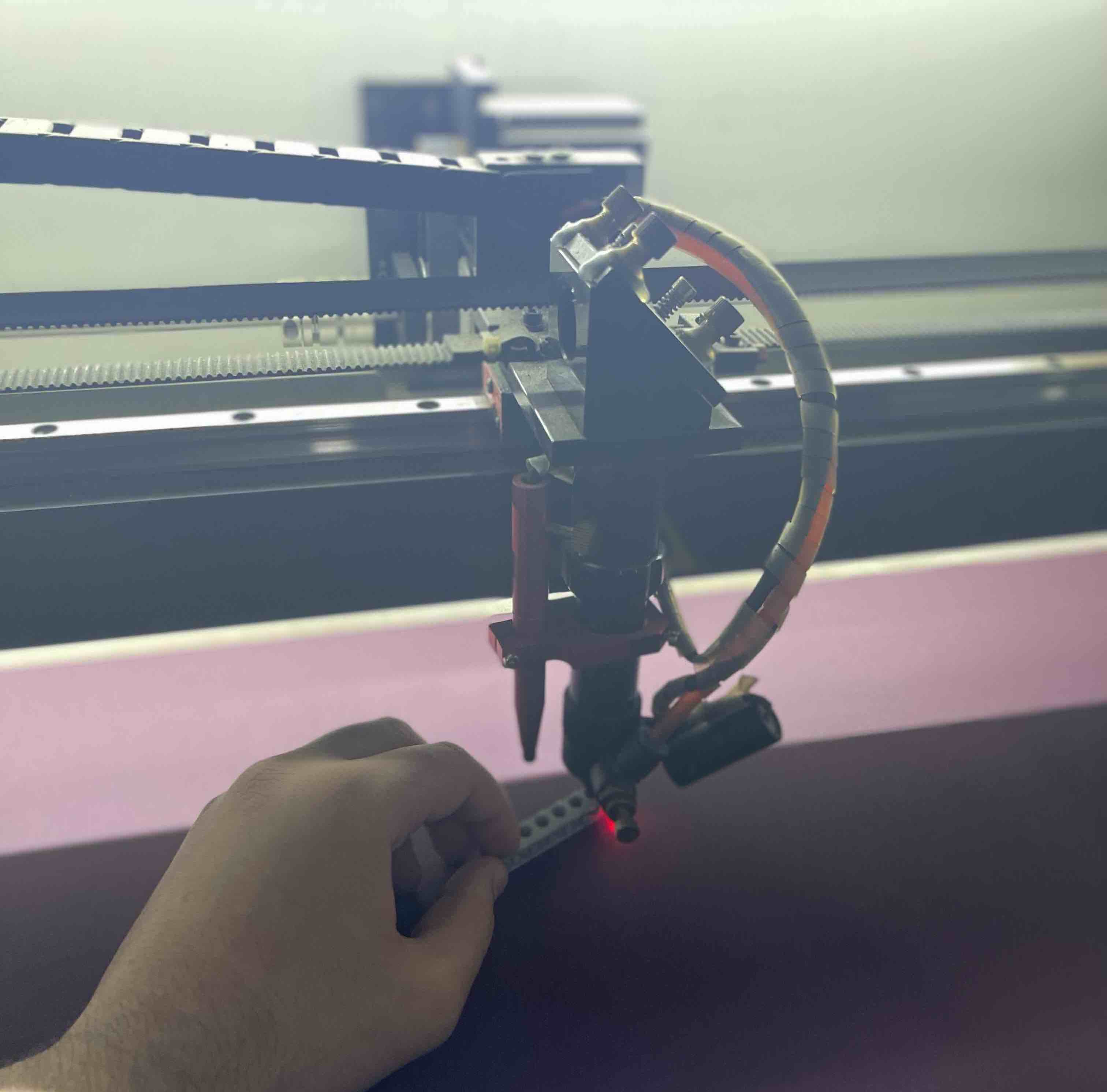
Before we could use the machine, we had to set a lego, which let us determine the exact distance between the laser beam and the bed where the materials lies. A lego is positioned directly between the laser beam and the bed in the image below.
For the group assignment, we first got to learn what is the machine, whats its purpose and how to proeperly operate it.
We began by determining the appropriate speed and power for cutting a circle, to test out what settings work best for the material we were working with. In this case we were dealing with a thin layer of pressed wood.
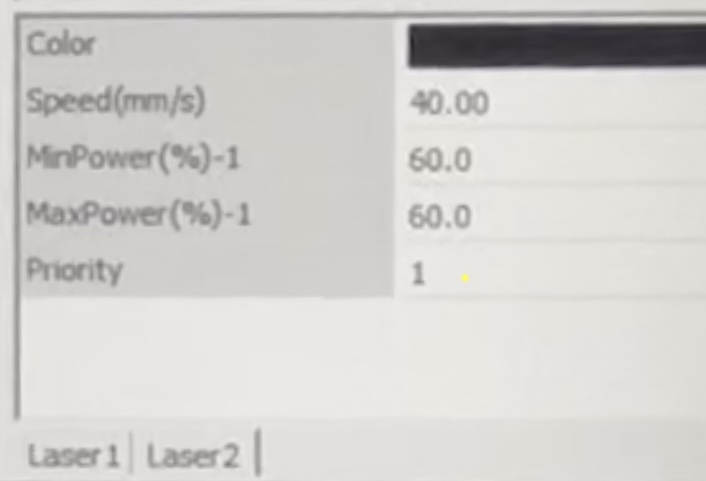
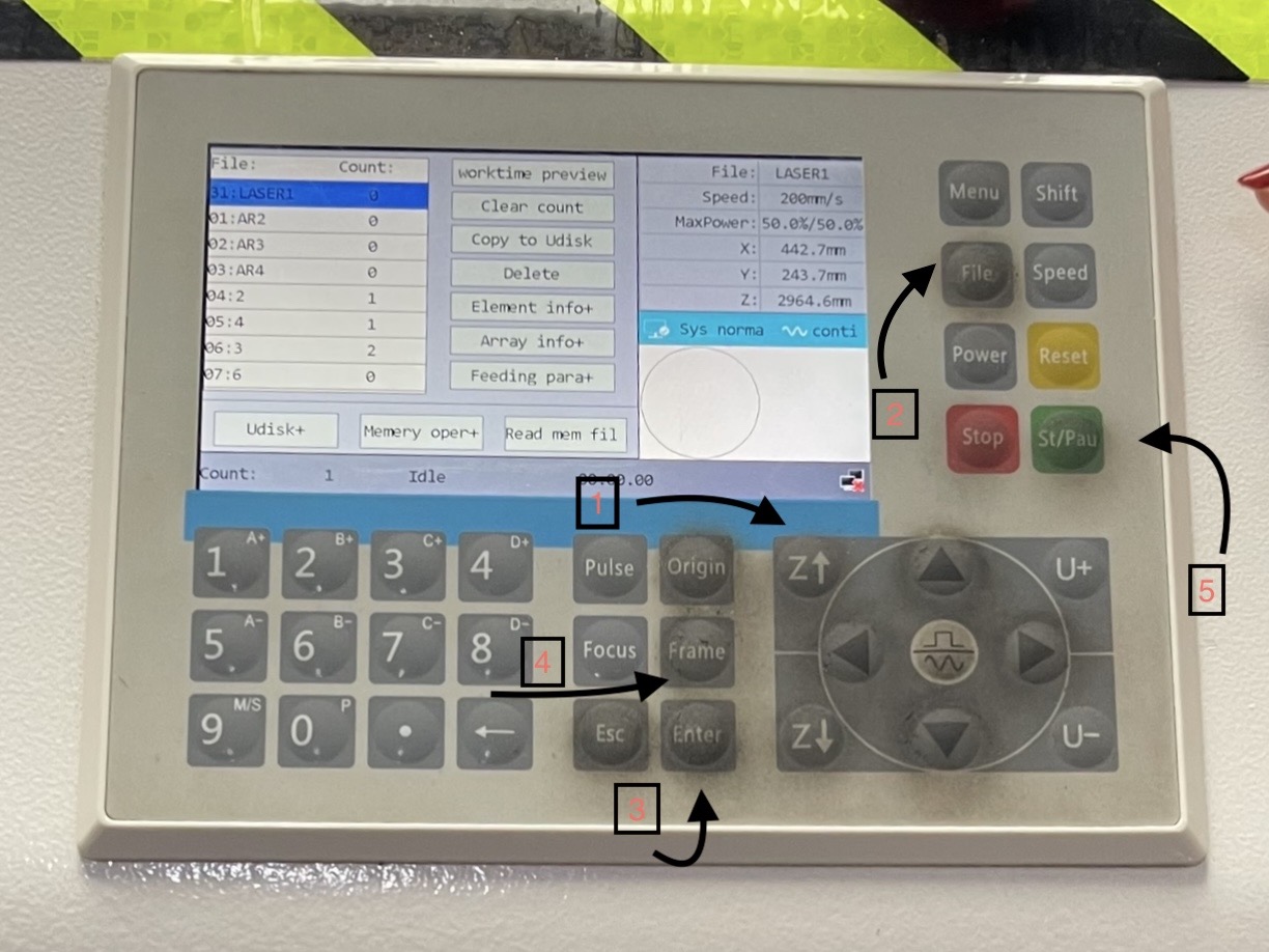
1. First, we drew a circle in the software, we set parameters for the shape we sketched on the grid, to ensure everything was in the right measurement, made sure its color was black and set the power to 60% and speed to 40mm/s and clicked yes on “Laser scan output”, on the operating screen on the laser cutting machine to set the laser beam in its origin position. Next, we clicked on files> chose the file of the circle we made in the software> Enter> Frame which frames exactly where the the beam will cut>Start to begin the cutting process.
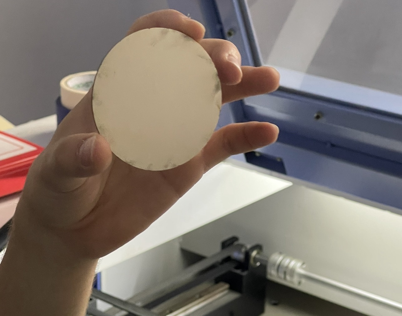
Here are the final results of the circle we cut with the setting mentioned above.
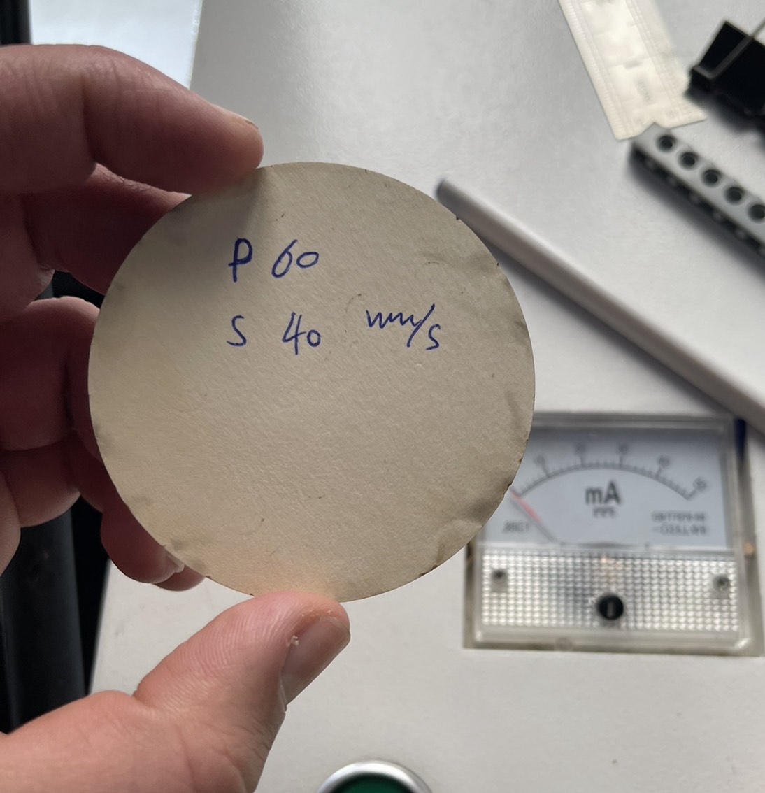
However, there were some burns surround the border of the circle, which indicates that the setting aren’t entirely ideal.
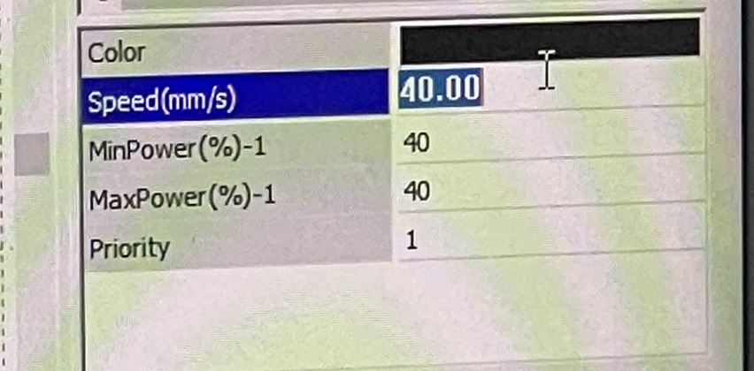
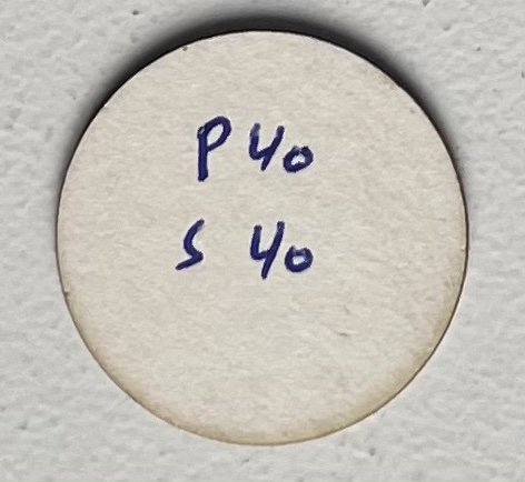
2. We then began to test out other setting, here we set the power to 40% and the speed to 40mm/s, which was great, but not ideal.
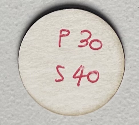
3. Then we changed the settings and increased the power to 30% while maintaining the speed; the results were satisfactory, and the burns were minor.
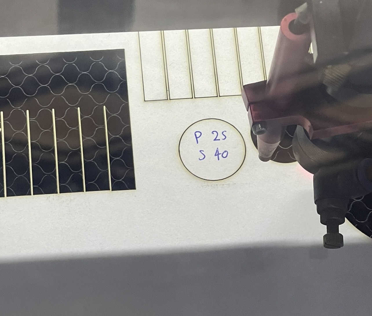
4. In this step, we reduced the power to 25% while maintaining the same speed of 40mm/s to see how the circular cut out would turn out and to keep the burn to a minimal. The outcomes were not what was expected, and it didn’t even made it out of the main wood board.
5. In this step we tested out the engraving settting that the machine performed, we set the speed to 400mm/s and power to power to 30%.
The settings we utilized and their outcomes are summarized in the table below.
| Setting | Outcome |
|---|---|
| Power 30%, Speed 40mm/s | Burns all over the borders |
| Power 40%, Speed 40mm/s | Some burns on the borders |
| Power 30%, Speed 40mm/s | Minimal burns on the borders |
| Power 25%, Speed 40mm/s | Didn’t cut through the material |
Joint Test
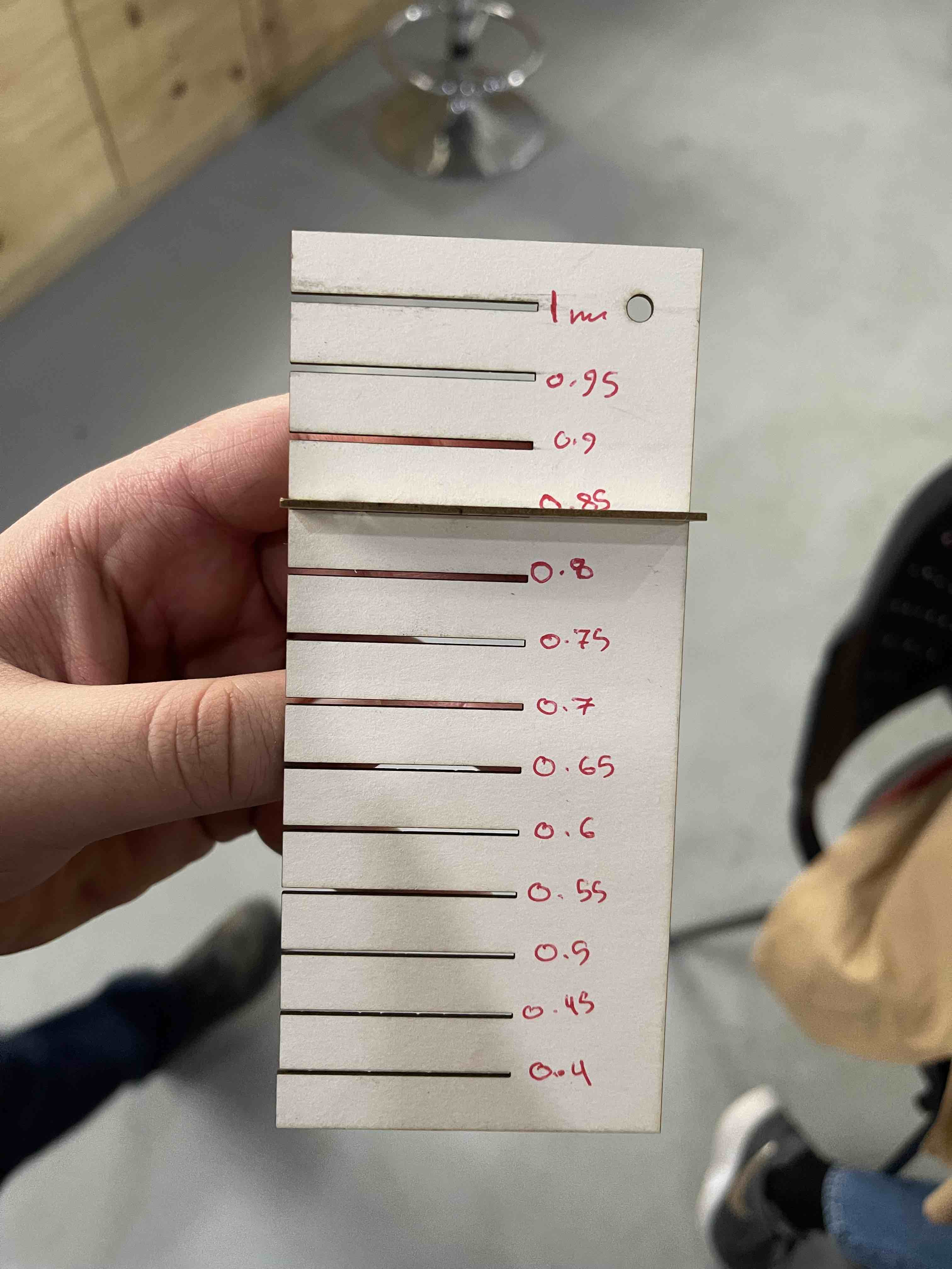
For this sort of test, we prepared a sample to test for the joints fitting at each measurement, which decreased by 0.5mm at each joint size. This sort of test will help us select the optimal joint fitting for when we develop our own designs and join them, using the same material.
1. We already had a drawing with pre-set parameters for the joint fitting test comb that we could use for the joint test. We set the speed to 35mm/s and the power at 30%. We chose the frame option so that we would know exactly where the comb would be drawn and not waste any of the material.
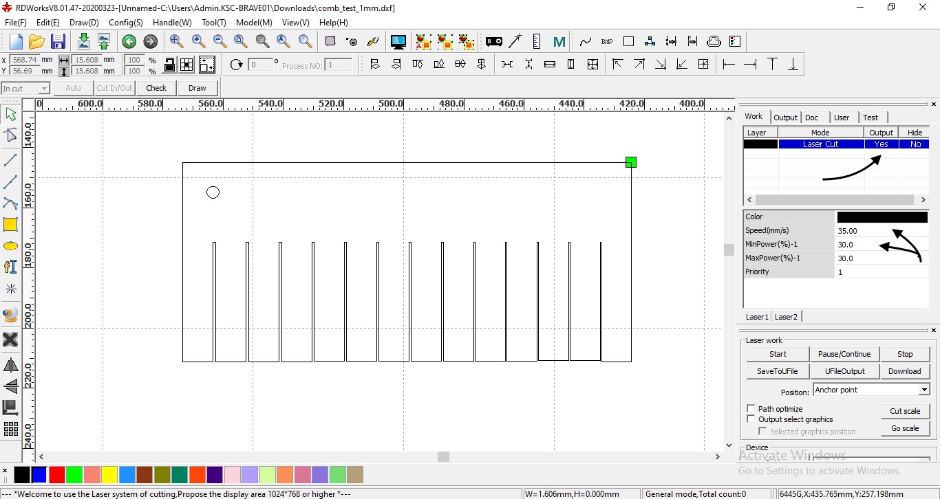
Then, we cut another comb using the same settings, which then will be used to join both comb together at each joint.
- We had to vote as a group which joint fit was the best, one that wasn’t too loose or too tight. We began by joining the 1mm joints of both combs, but they were too loose. We continued our attempts until we discovered that the 0.85mm joint of both combs connected well together, and we chose to adapt it for our individual assignment.
Indvidual Assignment
I went with a geometric lampshade for the individual assignment.
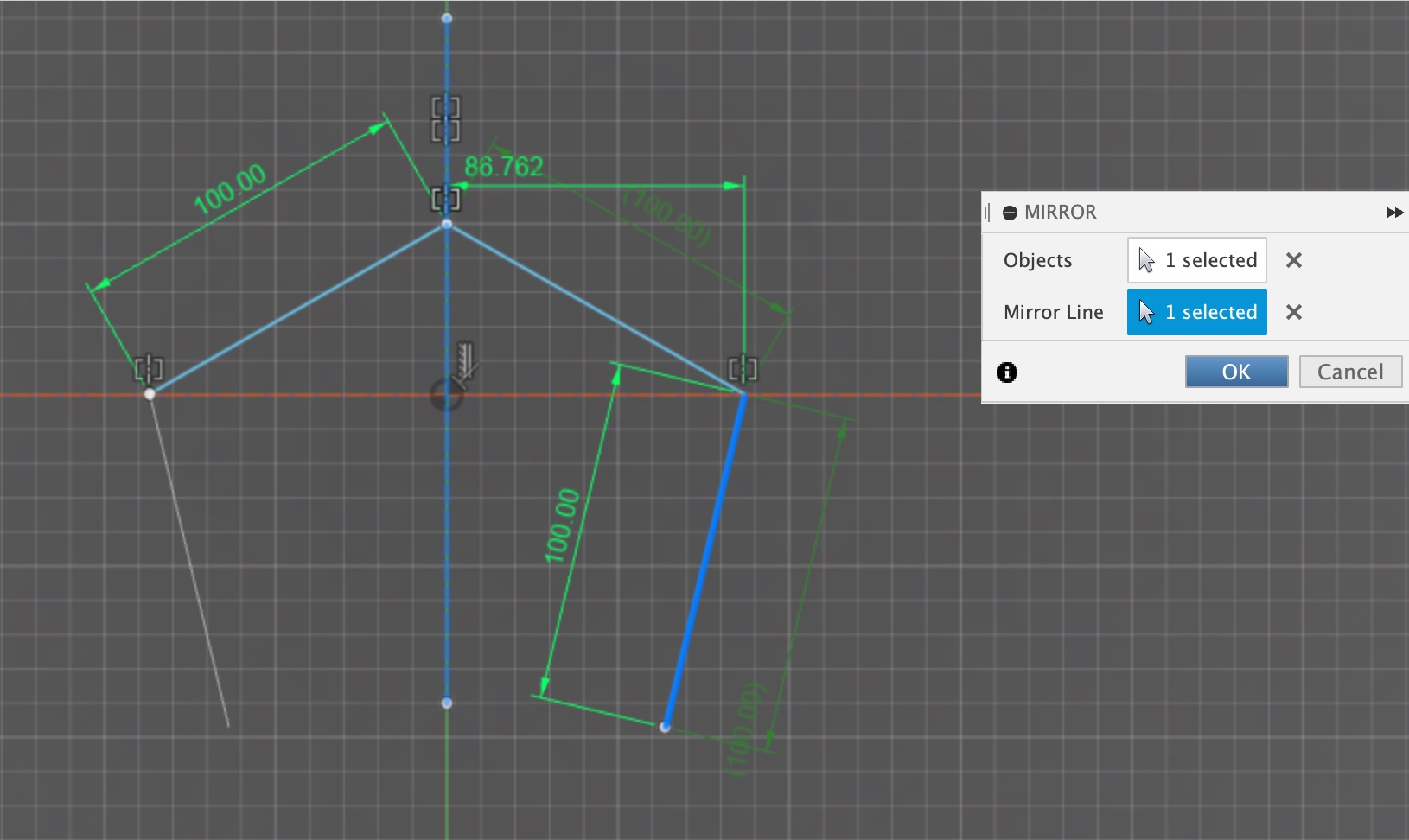
1. Using Fusin360 I started sketching my main shape which is going to be used as the shade of the lamp.
Using the mirror option, I ensured that all lines on one side of the construction line matched on the other side of the construction line.
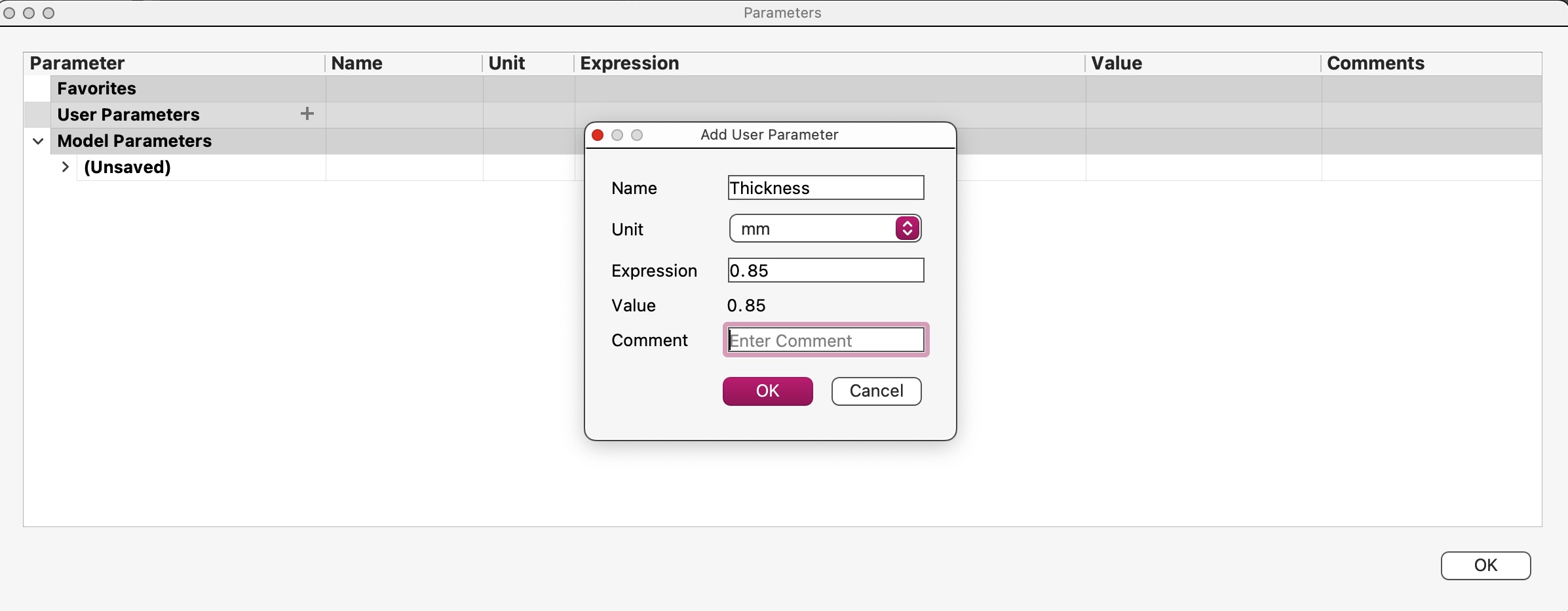
2. I utilized the parameters option to ensure that all joints were properly aligned and equal in size, shape, and, most crucially, width of 0.85mm, which my group and I chose to adopt.
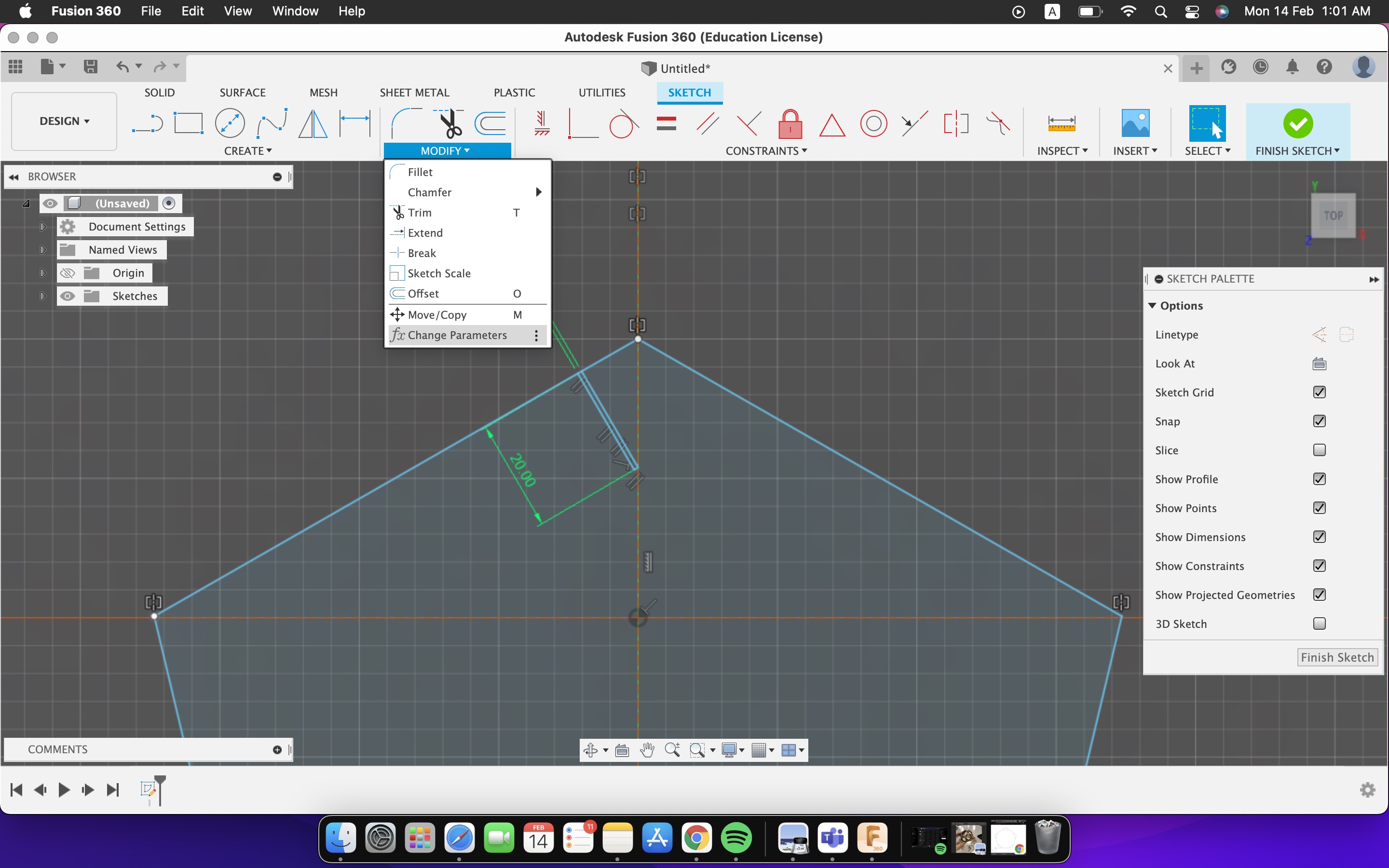
Here, I clicked on the (+) after opening the parameter windows to add a new parameter and named it thickness for the width of the joints.
While sketching the joint instead of entering the measurement each time I sketched a joint, I typed thickness which automatically set the rectangle to the measurement I initialized the parameter thickness with.
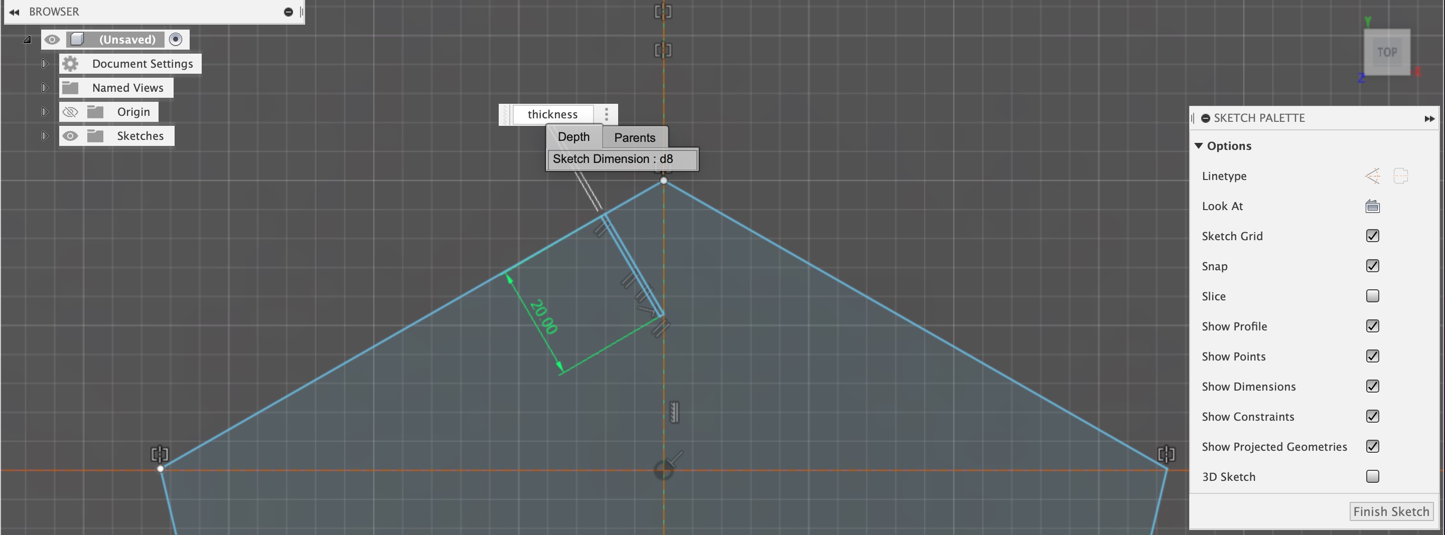
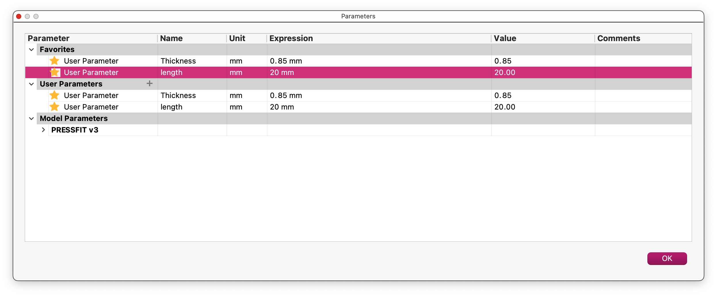
I then added another parameter to ensure that all of the joints have the same length.
Finally, I sketched the joint that joins the pieces together, making sure it was at an angle that worked with the shape.
3. When it came to the laser cutting, I first checked that the cardboard I was going to cut was properly positioned on the machine bed. To avoid wasting any material, I shifted the laser beam to the corner of the cardboard, and framed where the cutting will take place.
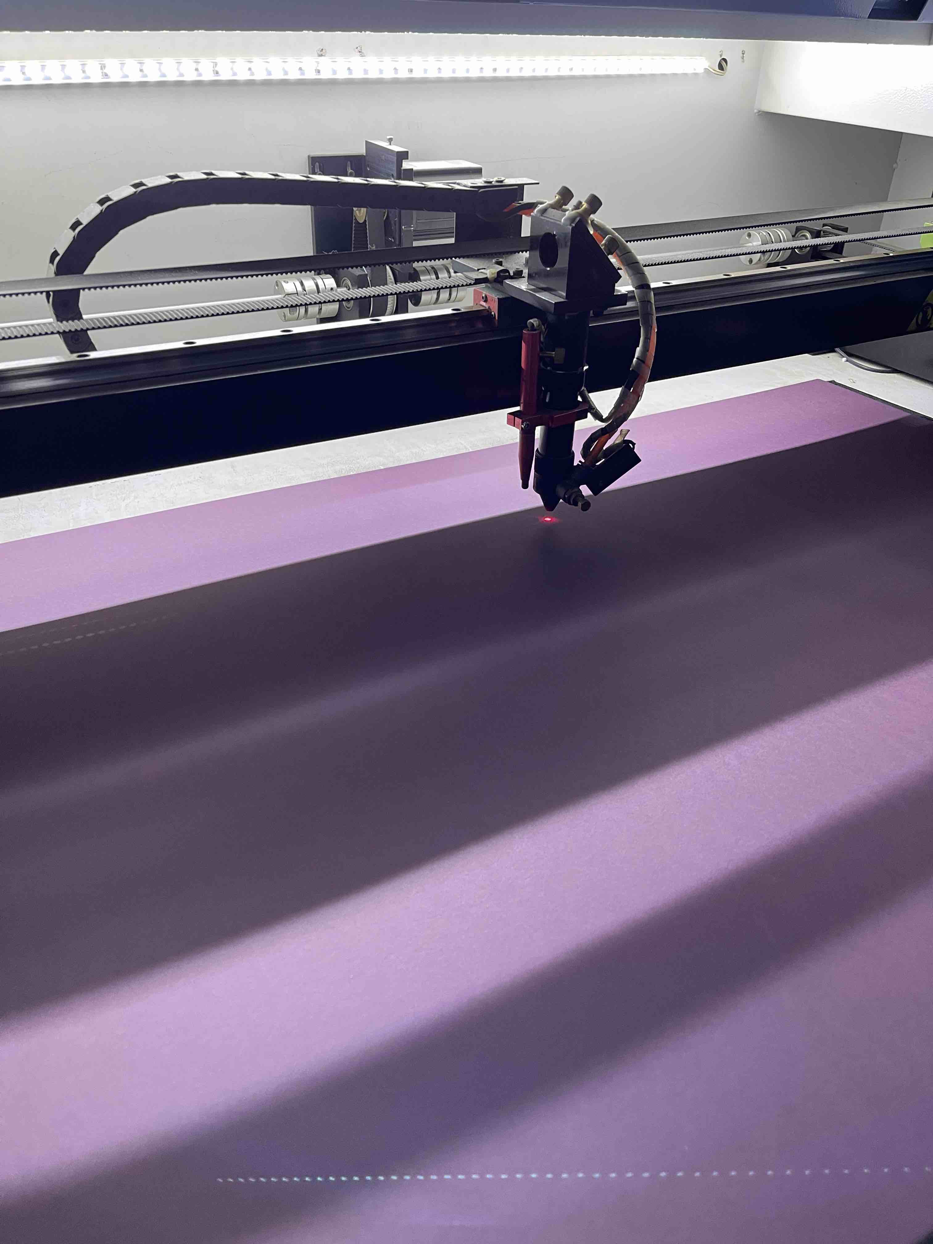
Then I placed the lego piece that we use to measure the distance between the laser beam and the materials on the machine’s bed.
Finally, I opened the file on the machine’s operating panel and selected start to begin the cutting process.
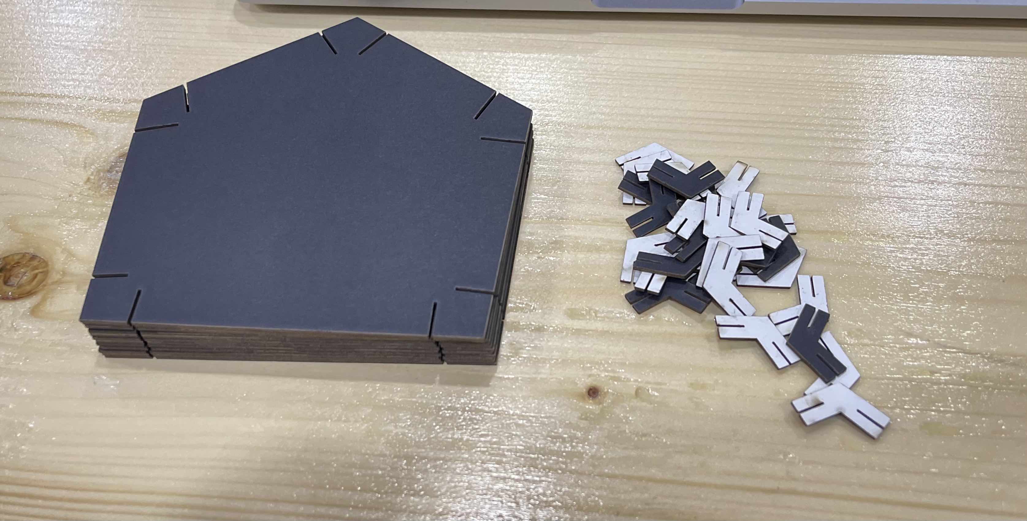
Here are the pieces before assembling
Final Results
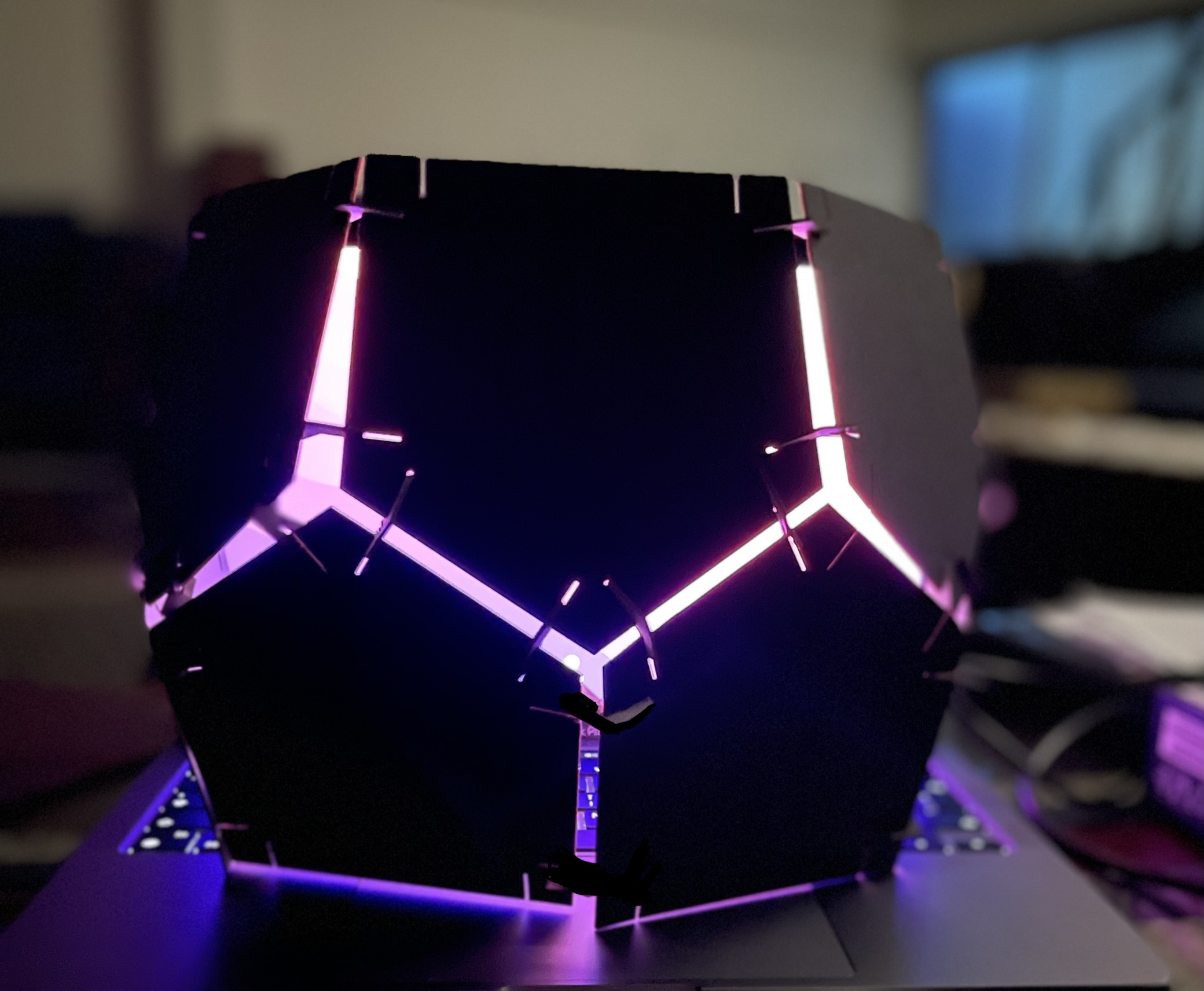
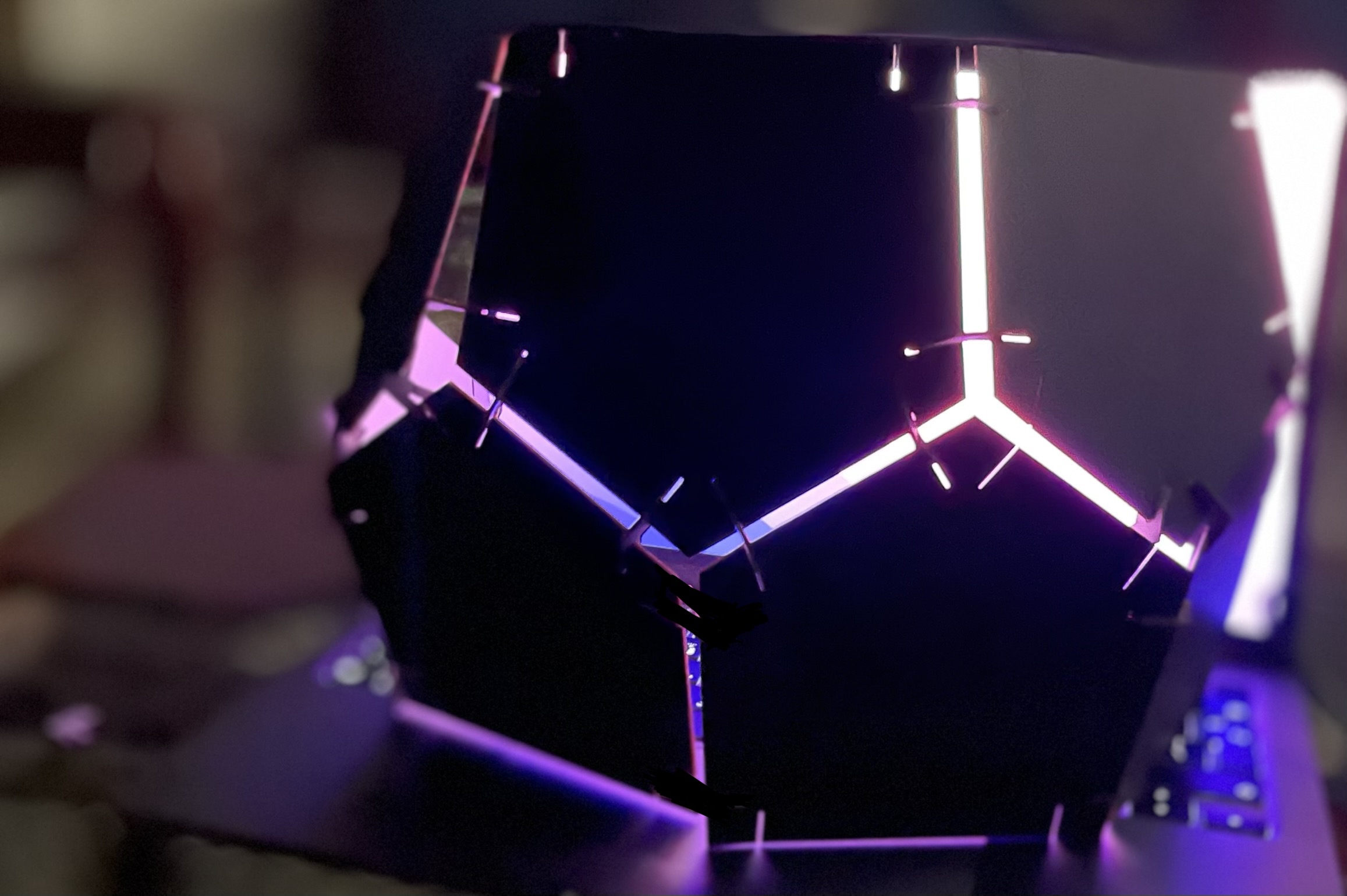
Click here to download the sketches file.