4. Embedded programming
This week, I learnt about multiple kinds of microcontrollers, as well as the fundamental distinctions between them, and how to program a microcontroller.
What is a microconrtoller?
A microcontroller is an integrated circuit (IC) device that uses a microprocessor unit (MPU), memory, and various peripherals to control other parts of an electronic system. These devices are designed for embedded applications that demand processing capabilities as well as quick and rapid interaction with digital, analog, or electromechanical components.
On a single chip, a microcontroller has a CPU, program memory, RAM, input/output pins, and other components.
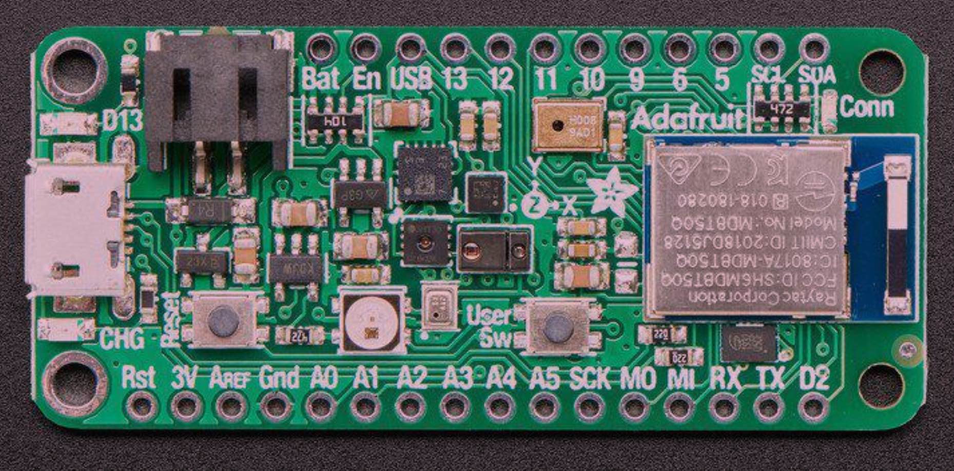
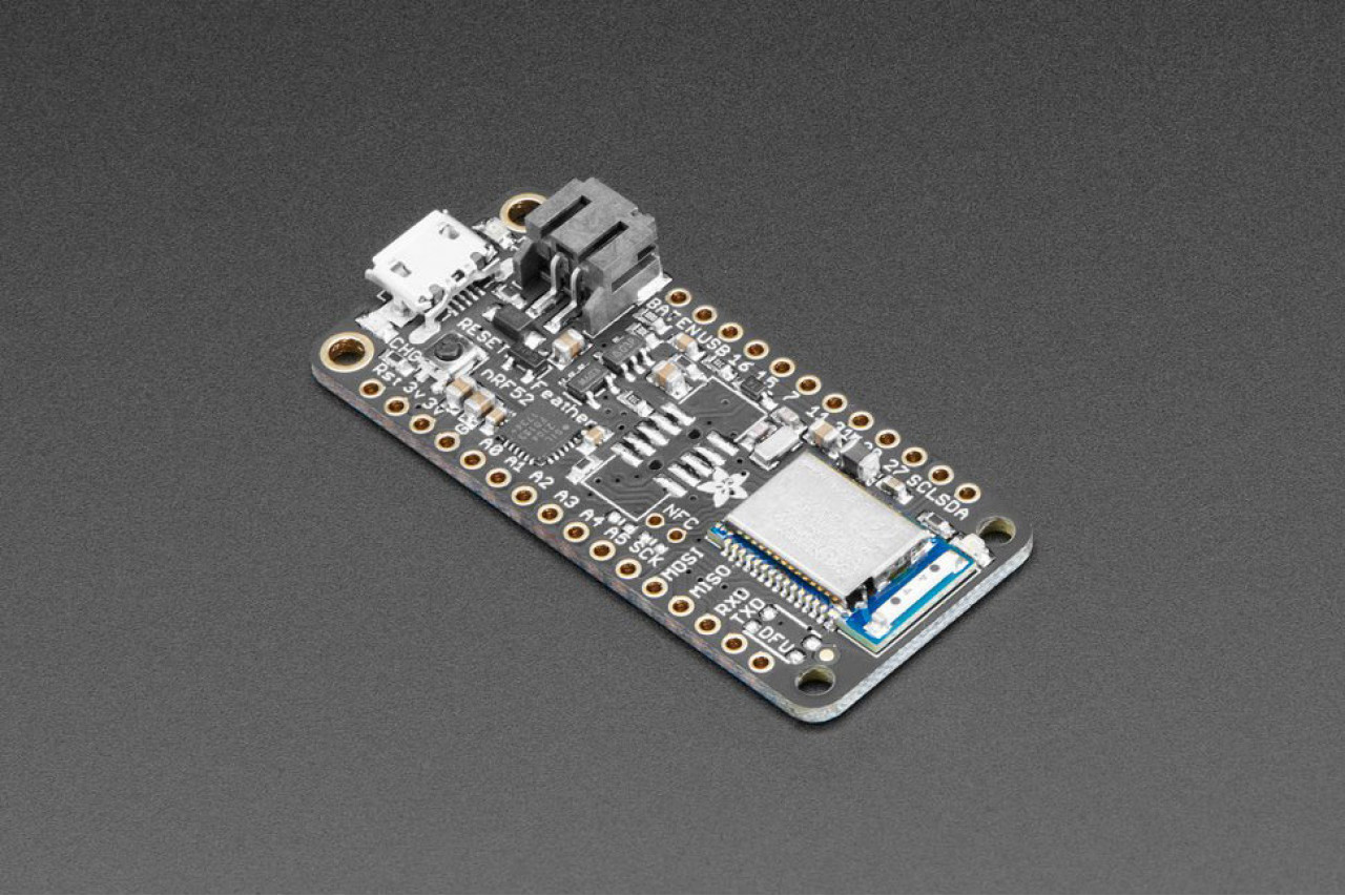
Below is an image of the microcontroller I programmed.
Research and Datasheet Interpretation
- The Adafruit microcontroller (also the one I used) is an ‘all-in-one’ Arduino- compatible + Bluetooth Low Energy with built in USB plus battery charging.
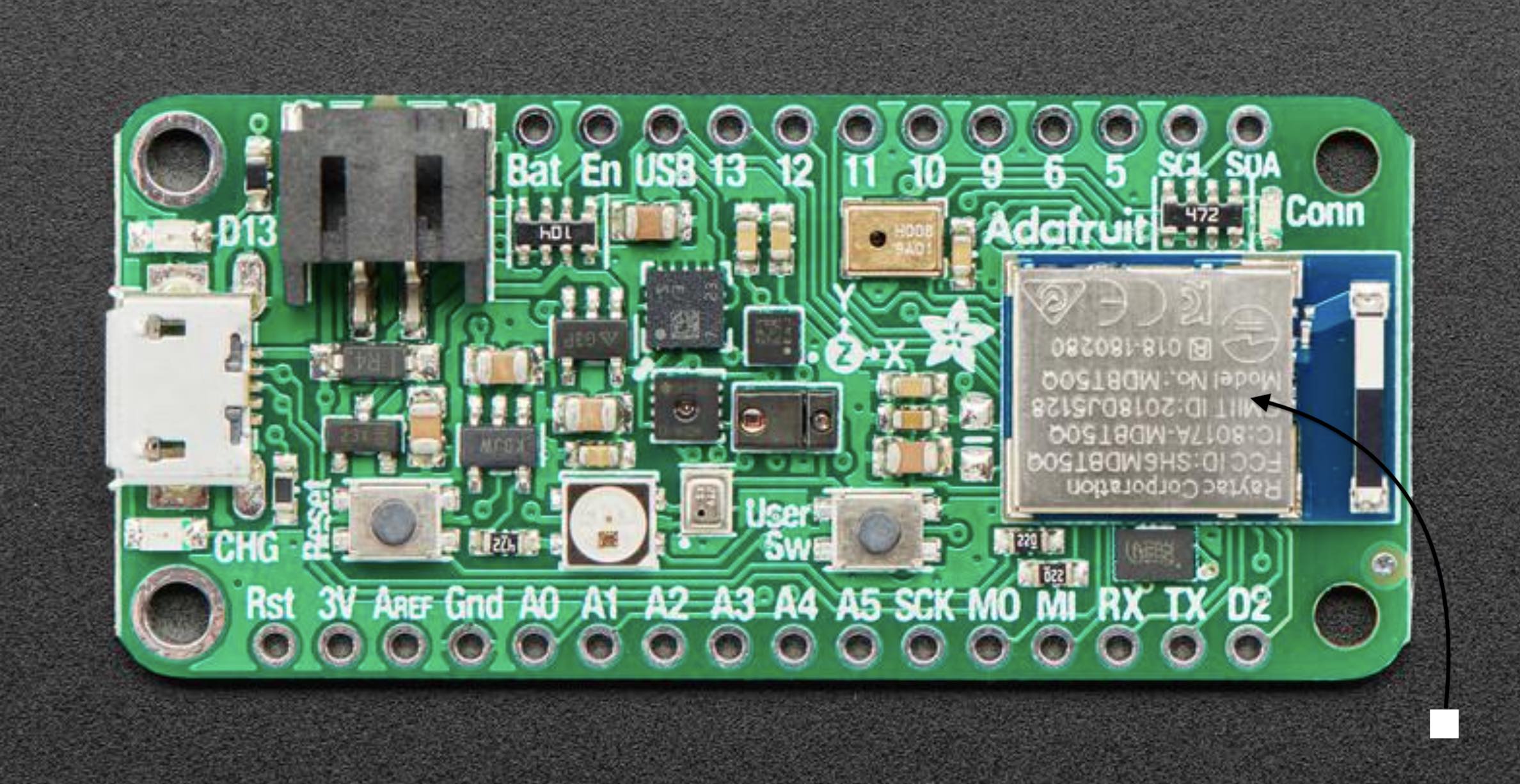
- The Microntroller has a Nordic nRF52840 Bluetooth LE processor - 1 MB of Flash, 256KB RAM, 64 MHz Cortex M4 processor.
- There are different types of pinouts: power pins, analog pins, PWM Outputs and I2C Pins.
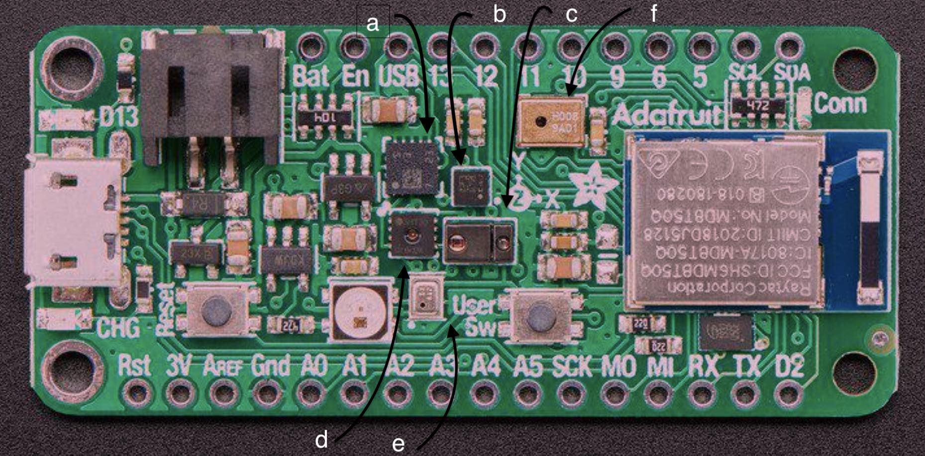
- There are several types of sensors integrated in the microcontroller, including:
- Gyro + Accel: LSM6DS33, which is an accelerometer + gyroscope.
- Magnetometer: LIS3MDL, which sense the magnetic fields that surround us.
- Light + Gesture + Proximity: APDS9960, it detects simple gestures (left to right, right to left, up to down, down to up are currently supported), return the amount of red, blue, green, and clear light, or return how close an object is to the front of the sensor.
- Humidity: SHT30, a humidity sensor that has an excellent ±2% relative humidity and ±0.5°C accuracy for most uses.
- Temp + Pressure: BMP280, This sensor is a precision sensing solution for measuring barometric pressure with ±1 hPa absolute accuracy, and temperature with ±1.0°C accuracy
- PDM Microphone sound sensor: MP34DT01-M - PDM sound sensor, senses sound and functions as a microphone.
- This USB port (USB Micro) is used for programming and/or powering the Feather Sense. It is a standard USB Micro connector.
- Battery - 2-pin JST PH connector for a battery. Power the Feather Sense from any 3V-6V power source, as it has internal regulator and protection diodes. You can also charge LiPoly batteries plugged into this connector using USB power.
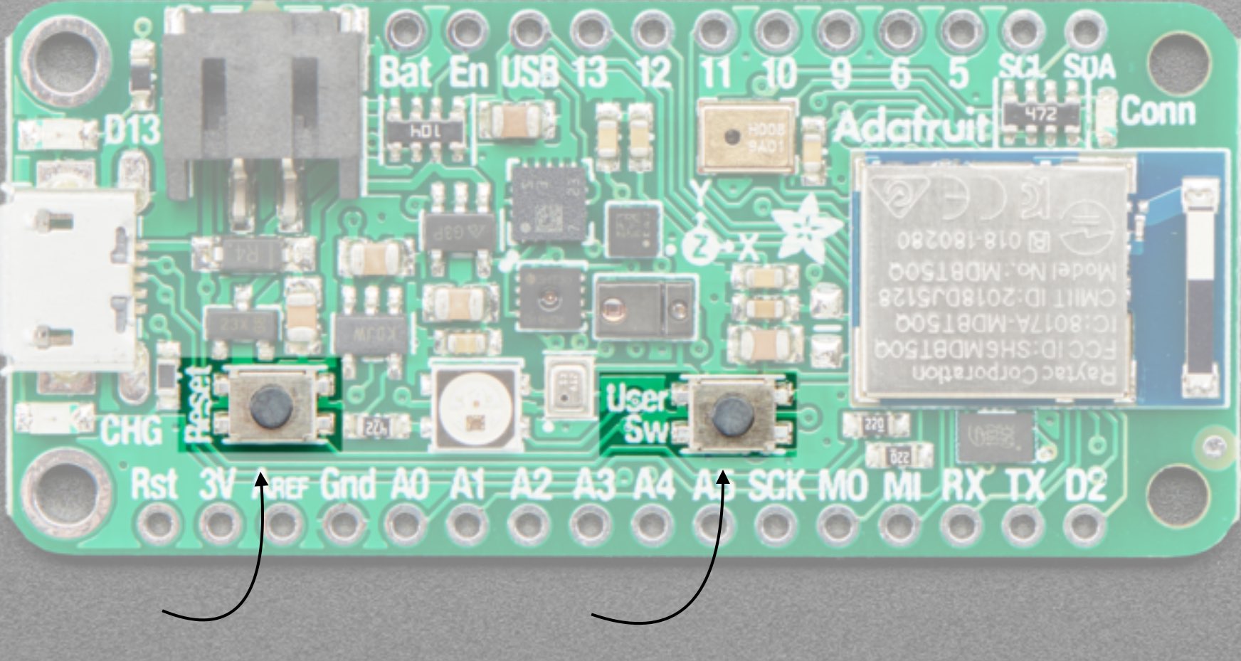
- It features two buttons: a reset button that resets the board when pressed once, and a double-click that enters the bootloader when pressed twice. The other button is the User button, which may be used by both the bootloader and the user.
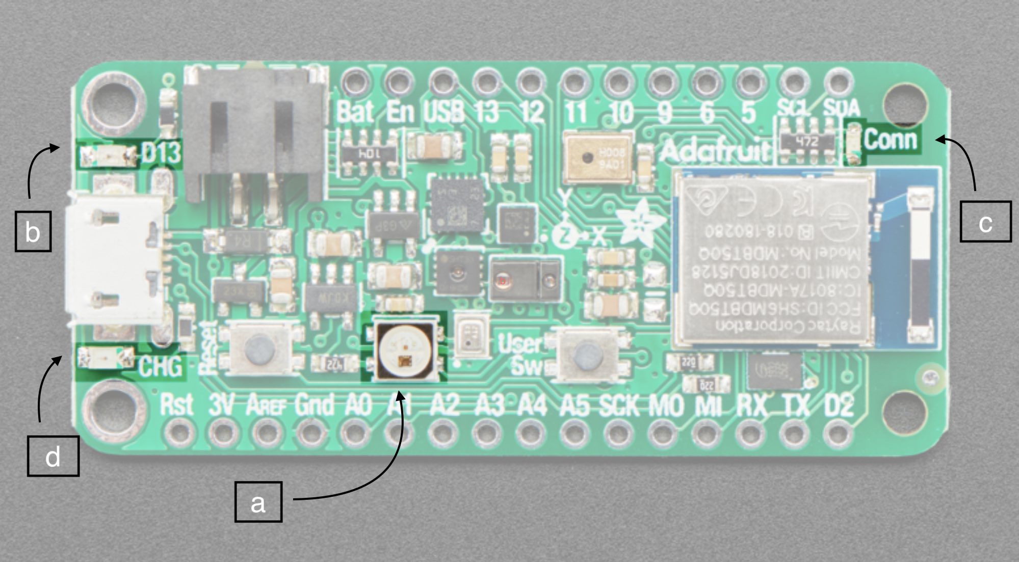
- There are two lighting options, NeoPixel and Status LEDs
- NeoPixel - The addressable RGB NeoPixel LED is used as a status LED by the bootloader and CircuitPython, but is also controllable using code.
- Red status LED - This little red LED, labeled D13, works as a status LED in the bootloader.
- Blue status LED - This little blue LED, labeled Conn, works as a connectivity status LED in Arduino, and is user-controllable in both Arduino and CircuitPython.
- Charge status LED - The little LED, labeled CHG, below the USB connector is the charge status LED. When no battery is connected, it flashes. When a battery is connected and charging, the LED is steady amber.
- There’s two ways to power a Feather. You can connect with a MicroUSB cable (just plug into the jack) and the Feather will regulate the 5V USB down to 3.3V. You can also connect a 4.2/3.7V Lithium Polymer (Lipo/Lipoly) or Lithium Ion (LiIon) battery to the JST jack. This will let the Feather run on a rechargable battery. When the USB power is powered, it will automatically switch over to USB for power, as well as start charging the battery (if attached) at 200mA. This happens ‘hotswap’ style so you can always keep the Lipoly connected as a ‘backup’ power that will only get used when USB power is lost.
Click here to view the data sheet
Group Assignment
The first part of the group assignment is documented in Mohammed Alghazali website
The second part of the group assignment is documented in Qassim Nader website
Arduino Setup
First, I downloaded Arduino and followed the instructions on this page for setting it up so that I could program the microcontroller I had.
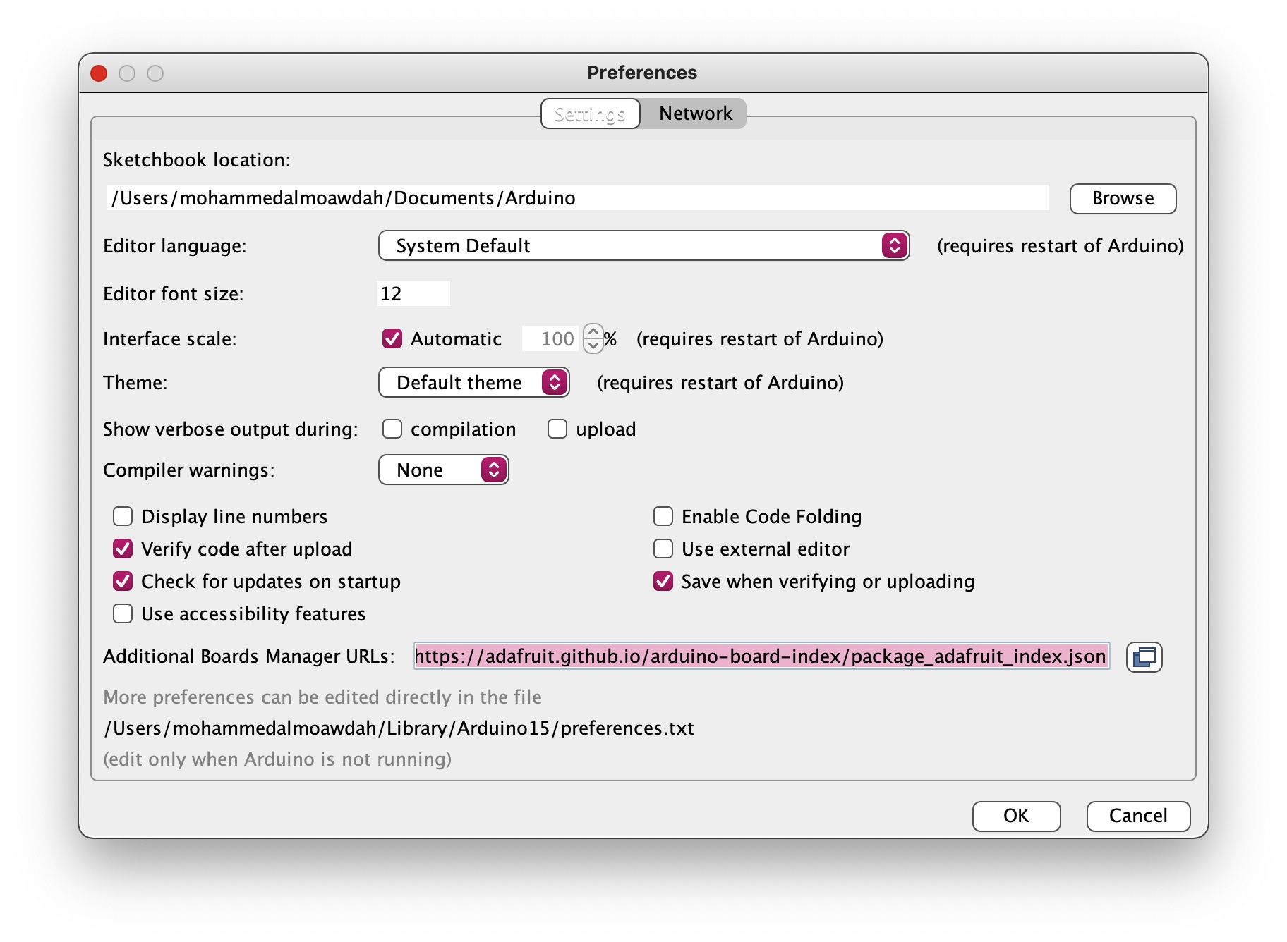
Then, I had to download the board support pacakage (BSP), I went to prefrences and copied the link that was available in the instruction website.
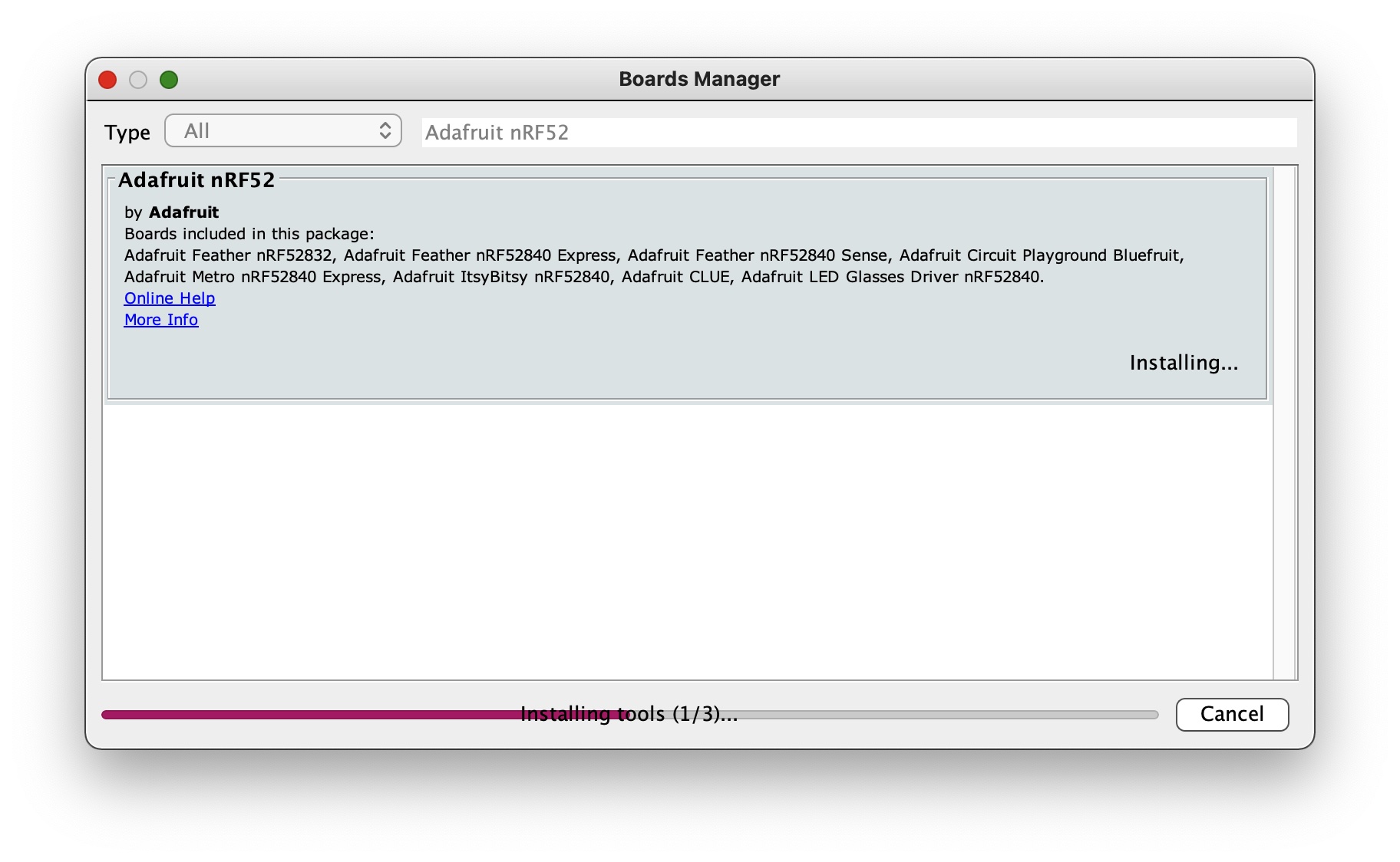
Next, I moved to the board manager where I searched for ‘Adafruit nRF52 by Adafruit’ and installed it
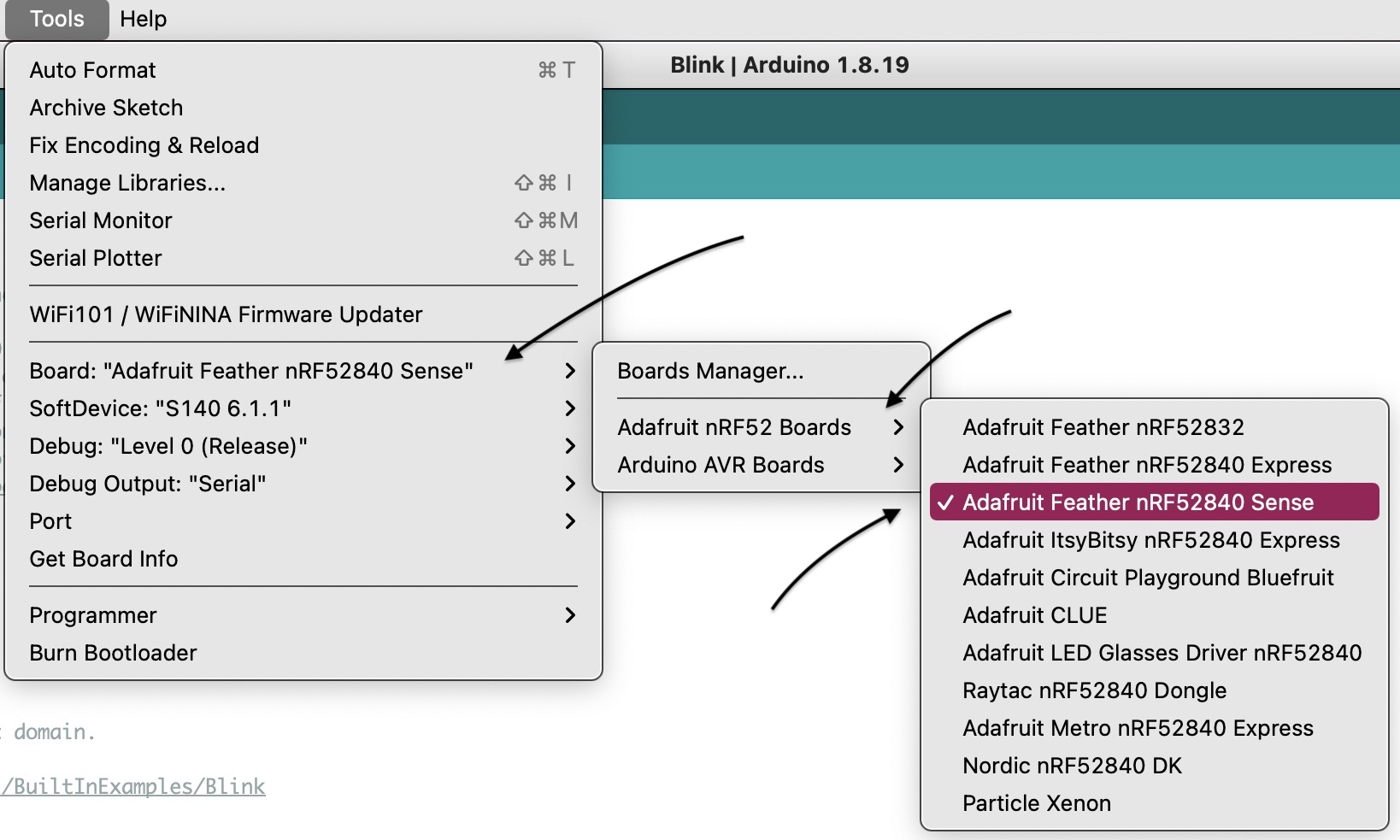
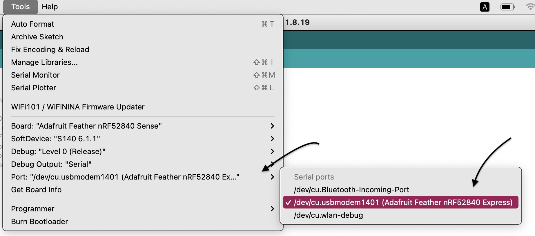
Afterwards, I clicked on Tools> Boardmanager> chose Adafruit nRF52… sense. and then I chose Port> and chose Adafruit nRF52… Express which connected the program to my microcontroller.
Programming
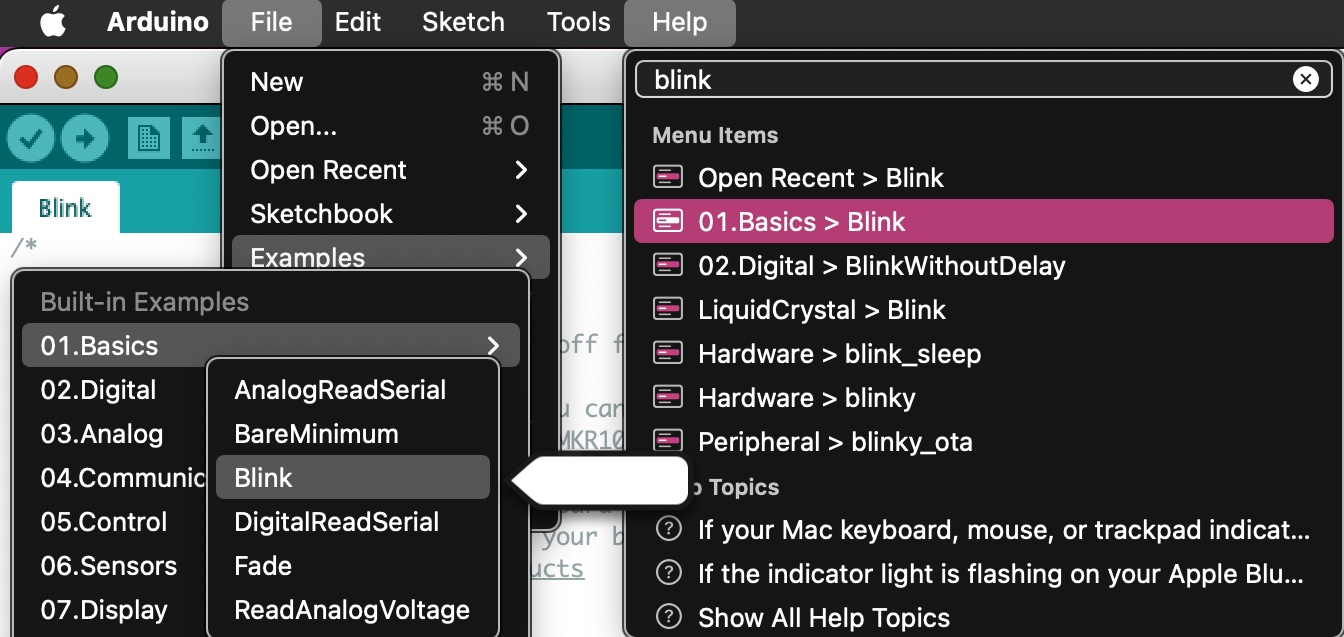
I used the help search engine to look up Blink, a built-in simple code that makes your microcontroller to turn LED on for one second, then off for one second, repeatedly.
Below is the program, with no modifications from my side.
void setup() {
  // initialize digital pin LED_BUILTIN as an output.
  pinMode(LED_BUILTIN, OUTPUT);
}

// the loop function runs over and over again forever
void loop() {
  digitalWrite(LED_BUILTIN, HIGH);   // turn the LED on (HIGH is the voltage level)
  delay(1000);                       // wait for a second
  digitalWrite(LED_BUILTIN, LOW);    // turn the LED off by making the voltage LOW
  delay(1000);                       // wait for a second
}
I then made some changes to the code creating a delay of 3 seconds between each and every blink, by setting the low volatge LED to 3000 as in the code below:
void setup() {
  // initialize digital pin LED_BUILTIN as an output.
  pinMode(LED_BUILTIN, OUTPUT);
}

// the loop function runs over and over again forever
void loop() {
  digitalWrite(LED_BUILTIN, HIGH);   // turn the LED on (HIGH is the voltage level)
  delay(1000);                       // wait for a second
  digitalWrite(LED_BUILTIN, LOW);    // turn the LED off by making the voltage LOW
  delay(3000);                       // wait for a second
}
Here is a video documenting the delay between two blinks:
TinkerCAD
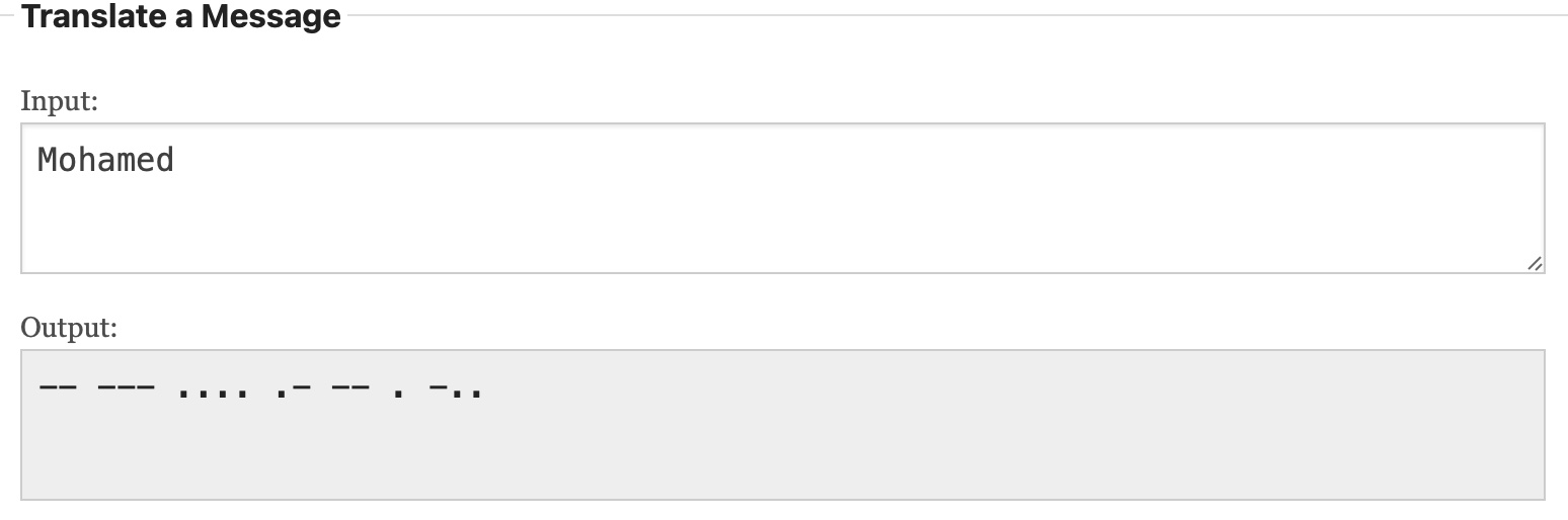
I programmed a virtual microcontroller in TinkerCad to light up my name in Morse code.
1. To convert my name to Morse code, I first searched for Morse code translator.
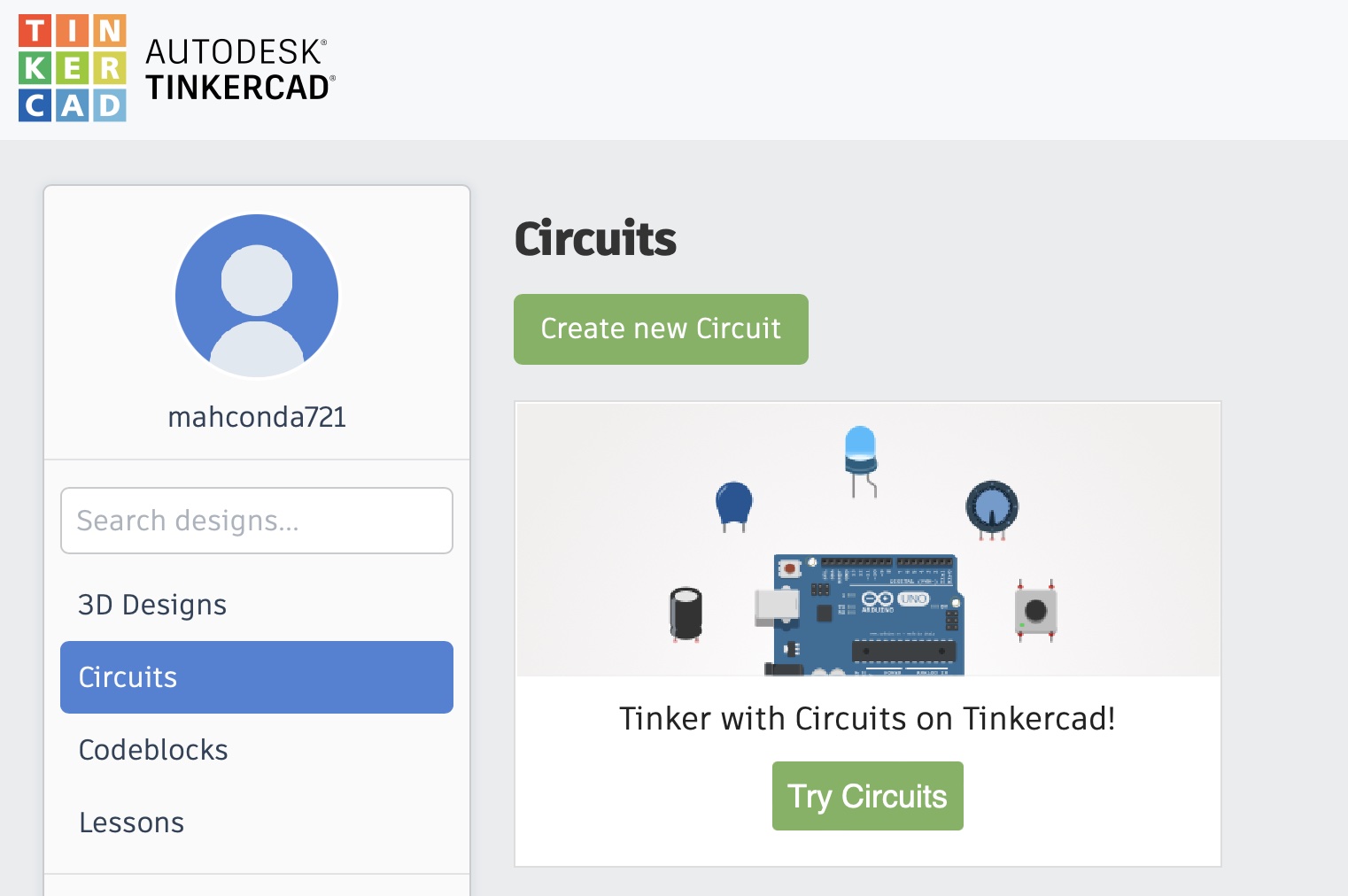
2. Now, to begin the actual process of programming the virtual microcontroller, I opened TinkerCAD clicked on Circuits from the left panel, and then Create new circuit.
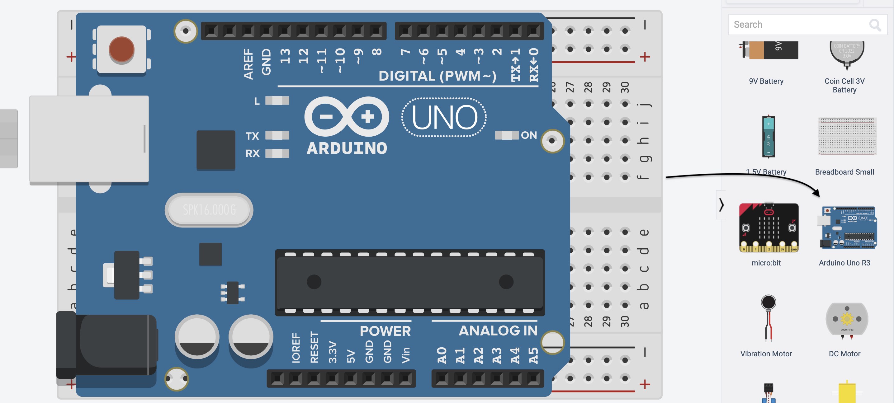
I then placed an Arduino UNO microcontroller in the working space.
3. In this step, where i began programming, I first had to make a note of ratio of the delays between each and every dot/dash/space which was given out by the instructor, which was 1 sec dash (-), 0.5 sec dot (.), 0.25 sec delay for socaes in a letter, 2 sec delay for spaces between two letters.
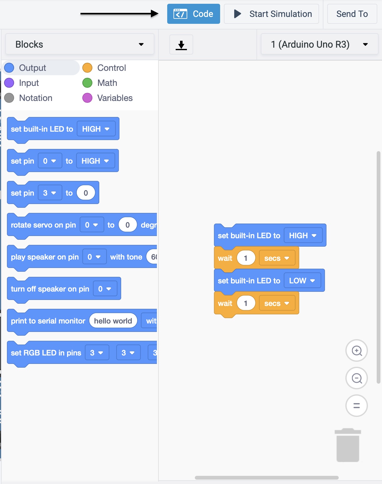
After gathering that information, I used the Code button at the top of the page to create a panel on the right side of the screen that displays code blocks, as seen in the image below.
Using the ouput set buit-in LED High and wait … secs these codes represented for how long the light will stay on, and other block of code: set buit-in LED Low and wait … secs represented for how many seconds the light will stay off.
So on, I started programming the rest of the Morse code, being sure to save time by using the repeat function for identical blocks of codes.
Below is a screen recording of the microcontoller lighting up my name in Morse code.
Below is the code rewrite
// C++ code
//
int counter;

int counter2;

int counter3;

void setup()
{
  pinMode(LED_BUILTIN, OUTPUT);
}

void loop()
{
  digitalWrite(LED_BUILTIN, HIGH);
  delay(1000); // Wait for 1000 millisecond(s)
  digitalWrite(LED_BUILTIN, LOW);
  delay(250); // Wait for 250 millisecond(s)
  digitalWrite(LED_BUILTIN, HIGH);
  delay(1000); // Wait for 1000 millisecond(s)
  digitalWrite(LED_BUILTIN, LOW);
  delay(2000); // Wait for 2000 millisecond(s)
  for (counter = 0; counter < 2; ++counter) {
    digitalWrite(LED_BUILTIN, HIGH);
    delay(1000); // Wait for 1000 millisecond(s)
    digitalWrite(LED_BUILTIN, LOW);
    delay(250); // Wait for 250 millisecond(s)
  }
  digitalWrite(LED_BUILTIN, HIGH);
  delay(1000); // Wait for 1000 millisecond(s)
  digitalWrite(LED_BUILTIN, LOW);
  delay(2000); // Wait for 2000 millisecond(s)
  for (counter2 = 0; counter2 < 3; ++counter2) {
    digitalWrite(LED_BUILTIN, HIGH);
    delay(500); // Wait for 500 millisecond(s)
    digitalWrite(LED_BUILTIN, LOW);
    delay(250); // Wait for 250 millisecond(s)
  }
  digitalWrite(LED_BUILTIN, HIGH);
  delay(500); // Wait for 500 millisecond(s)
  digitalWrite(LED_BUILTIN, LOW);
  delay(2000); // Wait for 2000 millisecond(s)
  digitalWrite(LED_BUILTIN, HIGH);
  delay(500); // Wait for 500 millisecond(s)
  digitalWrite(LED_BUILTIN, LOW);
  delay(250); // Wait for 250 millisecond(s)
  digitalWrite(LED_BUILTIN, HIGH);
  delay(1000); // Wait for 1000 millisecond(s)
  digitalWrite(LED_BUILTIN, LOW);
  delay(2000); // Wait for 2000 millisecond(s)
  digitalWrite(LED_BUILTIN, HIGH);
  delay(1000); // Wait for 1000 millisecond(s)
  digitalWrite(LED_BUILTIN, LOW);
  delay(250); // Wait for 250 millisecond(s)
  digitalWrite(LED_BUILTIN, HIGH);
  delay(1000); // Wait for 1000 millisecond(s)
  digitalWrite(LED_BUILTIN, LOW);
  delay(2000); // Wait for 2000 millisecond(s)
  digitalWrite(LED_BUILTIN, HIGH);
  delay(500); // Wait for 500 millisecond(s)
  digitalWrite(LED_BUILTIN, LOW);
  delay(2000); // Wait for 2000 millisecond(s)
  digitalWrite(LED_BUILTIN, HIGH);
  delay(1000); // Wait for 1000 millisecond(s)
  digitalWrite(LED_BUILTIN, LOW);
  delay(250); // Wait for 250 millisecond(s)
  digitalWrite(LED_BUILTIN, HIGH);
  for (counter3 = 0; counter3 < 2; ++counter3) {
    delay(500); // Wait for 500 millisecond(s)
    digitalWrite(LED_BUILTIN, LOW);
    delay(250); // Wait for 250 millisecond(s)
  }
}