7. Input & Output device
This week I learned about INPUT and OUTPUT, How to connect them to the MICROCONTROLLER and coding them.
what is an INPUT??
A device through which, energy , information or command enters a system.
what is an OUTPUT??
A device where the information or command converts into form . it can be movemnt,Audio or video …etc.
INPUT
The input I will be using is “KY-004 Button Module”
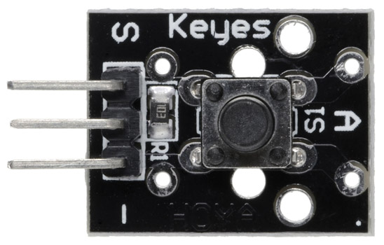
what is KY-004 Button Module??
As it names indicates its a button when pressing on the button it will give a signle or command and operates the output.
How to Connect it to a MICROCONTROLLER??
Pins
-
The pin in the left is the sensor pin that should be connected to the “Voultage 3V PIN”
-
The pin in the middile is the voltage should be connected to the “Degital PIN”.
-
The pin on the right is the minus pin That should be connected to the “GND PIN”
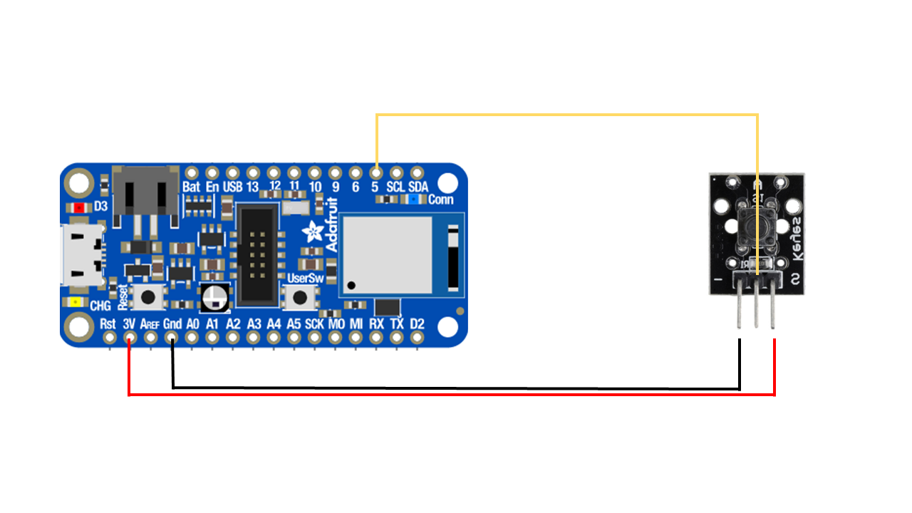
After Connecting the input to the microcontroller, I uploded the Code from the internet to test it out.
I had to fix the code a little bit to indicate the led light pin and the input pin which in my case it was 5.
picture
CODE
int buttonPin = 5;
int ledPin = 3;

bool buttonState = false;

void setup() {
pinMode(buttonPin,INPUT);
pinMode(ledPin,OUTPUT);

}
void loop() {

buttonState = digitalRead(buttonPin);

 if ( buttonState == true){
  digitalWrite(ledPin, HIGH);
 }
else {
  digitalWrite(ledPin, LOW);
}
VIDEO
OUTPUT
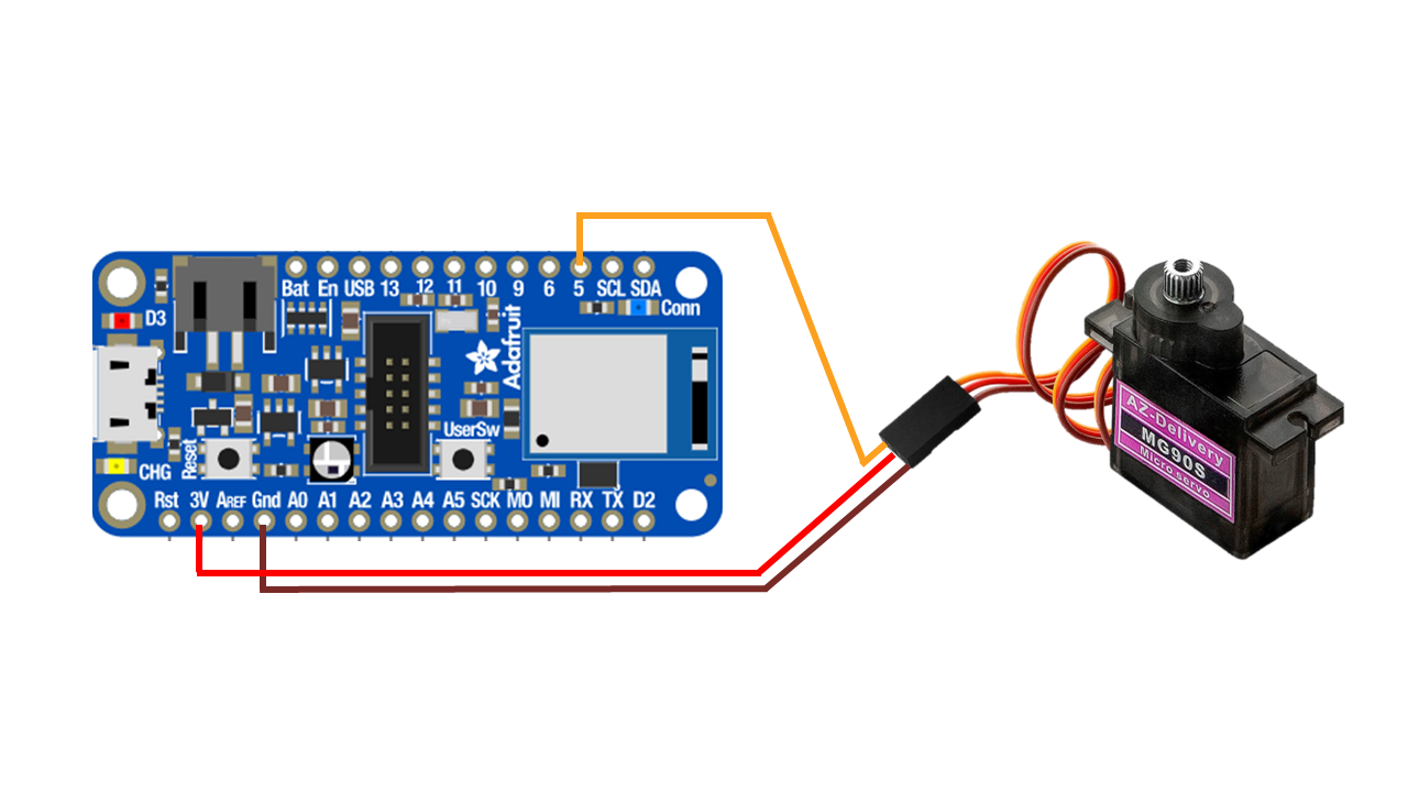
The output I will be using is a motor “MG90S”.
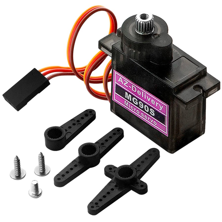
what is “MG90S” motor??
its a … motor
WHAT IT does??
How to Connect it to a MICROCONTROLLER??
-
The BROWN wire is the Groound-> connects to the “GND PIN”.
-
The Red wire is the Vcc-> connects to the “3V PIN”.
-
The YELLOW wire is the signle -> connects to the “Degital PIN”.
CODE
After Connecting the Output to the microcontroller, I uploded the Code from the internet to test it out.
The code didnt work.
picture of the error
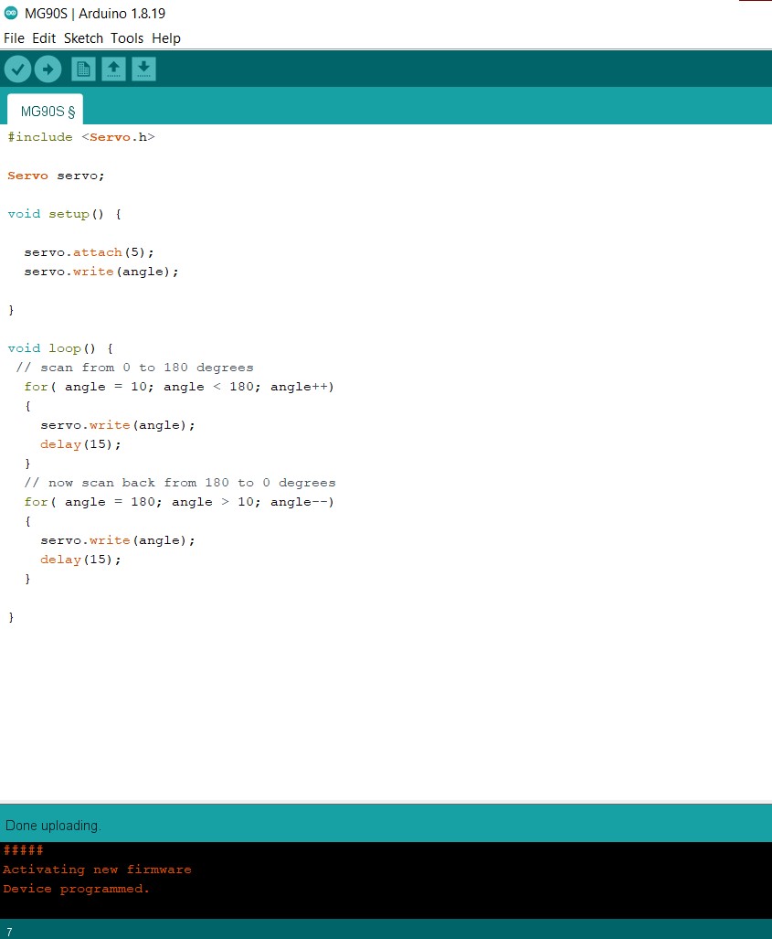
I had to modifiy the code a little bit by adding “int” infront of “angle”.
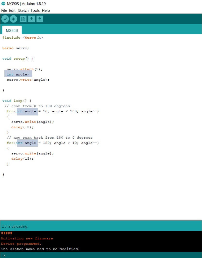
This Code worked
#include <Servo.h>
Servo servo;


void setup() {
  servo.attach(5);
  int angle;
  servo.write(angle);

}

void loop()


  {
  // scan from 0 to 180 degrees
  for(int angle = 10; angle < 180; angle++)
    servo.write(angle);
    delay (15);}

  }
  // now scan back from 180 to 0 degrees
  for(int angle = 180; angle > 10; angle--)
   servo.write(angle);
  delay (15);}
}
Video
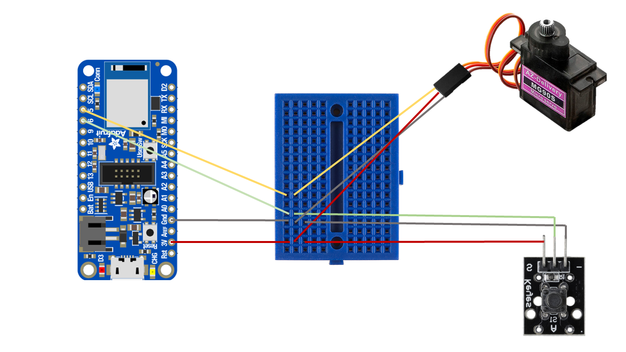
CONNECTING OUTPUT AND INPUT TO THE MICROCONTROLLER
How to Connect BOTH Input & Output to the MICROCONTROLLER??
In order to connect both to the microcontroller I used a breadboard.
what is a breadboard ??
A breadboard is a simple tool which is used to easily connect electrical components and wires together
CODE
As for the Coding I needed some help with it and it took some times to work after many trial and error.
#include <Servo.h>
Servo servo;
int buttonPin = 6;
bool buttonState = false;

void setup() {
  servo.attach(5);
  int angle;
  servo.write(angle);
  pinMode(buttonPin,INPUT);
  pinMode(LED_BUILTIN, OUTPUT);
}

void loop() {

  buttonState = digitalRead(buttonPin);

  if ( buttonState == true){
    digitalWrite(LED_BUILTIN, LOW);
 // scan from 0 to 180 degrees
  for(int angle = 10; angle < 180; angle++)
    servo.write(angle);
    delay (100);}

  else if (buttonState == false){
    digitalWrite(LED_BUILTIN, HIGH);
  // now scan back from 180 to 0 degrees
  for(int angle = 180; angle > 10; angle--)
    servo.write(angle);
  delay (100);}
}
Video