4. Embedded programming
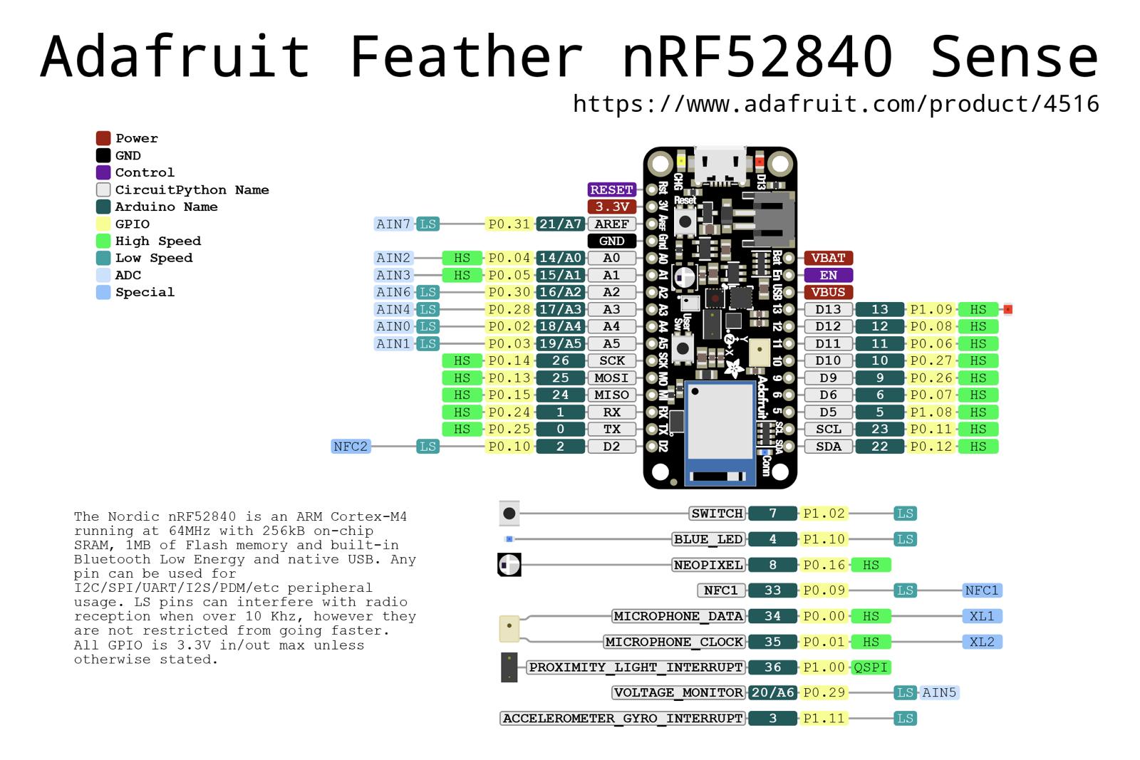
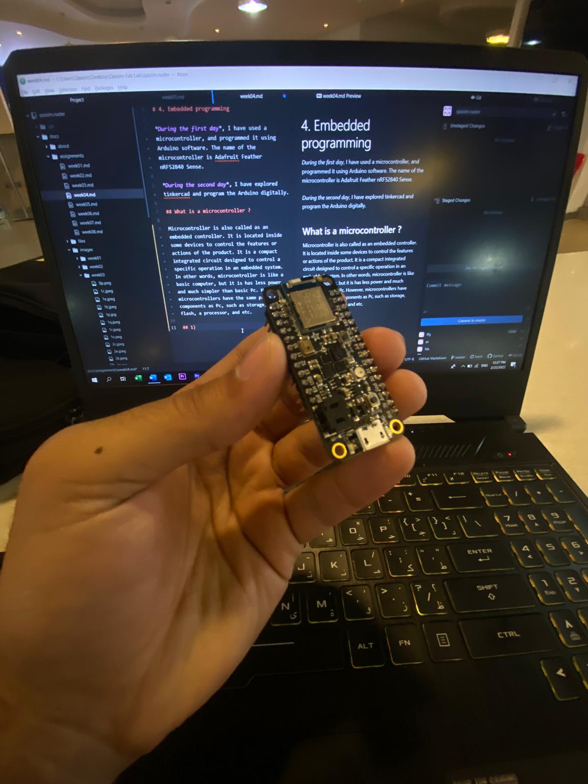
During the first day, I have used a microcontroller, and programmed it using Arduino software. The name of the microcontroller is Adafruit Feather nRF52840 Sense.
During the second day, I have explored tinkercad and programmed the Arduino digitally, and then used these codes and applied them in the microcontroller given using the Arduino software.
Microcontroller datasheet
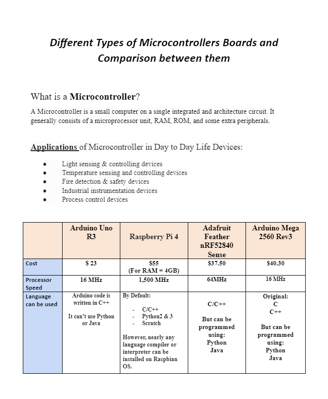
Microcontroller is also called as an embedded controller. It is located inside some devices to control the features or actions of the product. It is a compact integrated circuit designed to control a specific operation in an embedded system. In other words, microcontroller is like a basic computer, but it is has less power and much simpler than basic Pc. However, microcontrollers have the same parts or components as Pc, such as storage, ram, flash, a processor, and etc.
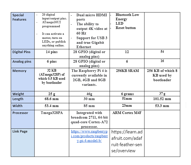
Features of Adafruit Feather nRF52840 Sense:
-
ARM Cortex M4F (with HW floating point acceleration) running at 64MHz
-
1MB flash and 256KB SRAM Native Open Source USB stack - pre-programmed with UF2 bootloader
-
Bluetooth Low Energy compatible 2.4GHz radio.
-
FCC / IC / TELEC certified module
-
Up to +8dBm output power
-
21 GPIO, 6 x 12-bit ADC pins, up to 12 PWM outputs (3 PWM modules with 4 outputs each)
-
Pin # 13 red LED for general purpose blinking, Blue LED for general purpose connection status, NeoPixel for colorful feedback
-
Power/enable pin
-
Measures 2.0” x 0.9” x 0.28” (51mm x 23mm x 7.2mm) without headers soldered in
-
Light as a (large?) feather - 6 grams
-
4 mounting holes
-
Reset button
-
SWD debug pads on bottom of PCB
Sensors in Adafruit Feather nRF52840 Sense:
-
APDS9960 Proximity, Light, Color, and Gesture Sensor (https://adafru.it/z0d)
-
BMP280 Temperature and Barometric Pressure/Altitude (https://adafru.it/fIK)
-
LIS3MDL Magnetometer (https://adafru.it/IfI)
-
LSM6DS33 Accel/Gyro (https://adafru.it/Iqd)
-
SHT31 Humidity (https://adafru.it/k6d) PDM Microphone (https://adafru.it/L-c)
The information was taken from these 2 useful links :
To learn more about Adafruit Feather nRF52840 Sense, click at this link
To learn more about Adafruit Feather nRF52840 Sense, click at this link
Downloading Arduino software
At the beginning of the session they gave us a microcontroller along with a usb cable. After that, we were asked to download Arduino software.
Click here to download the Arduino software
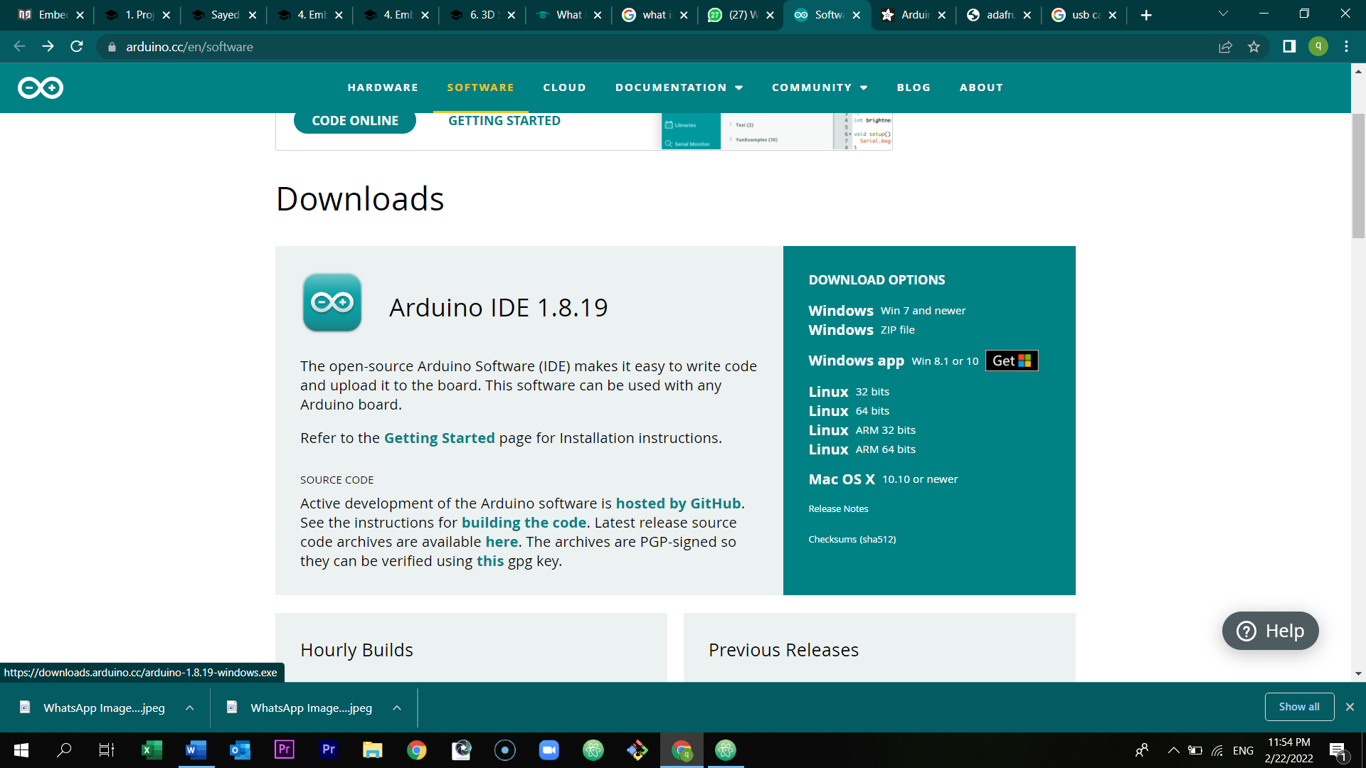
Here are the steps of how to download and start the program:
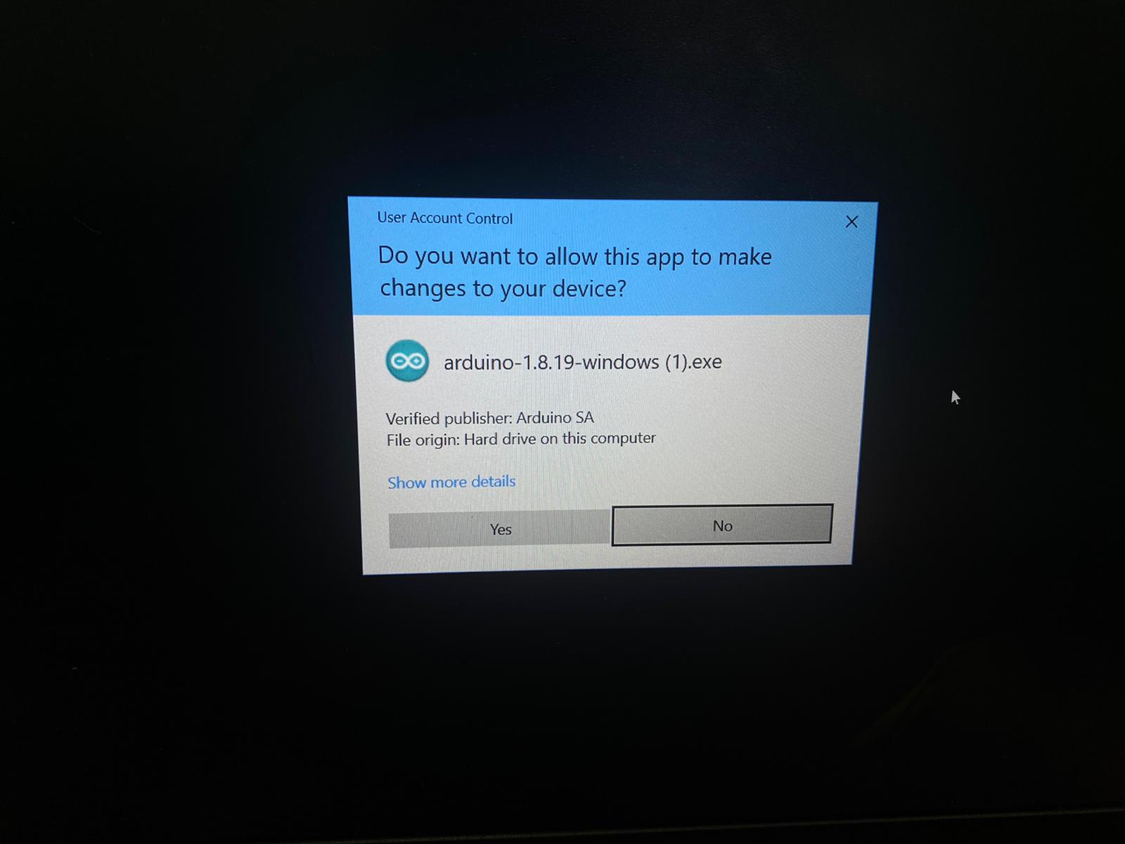
First of all, open the link above. Then, at the download option, click at windows 7 and newer.
Click at just download.
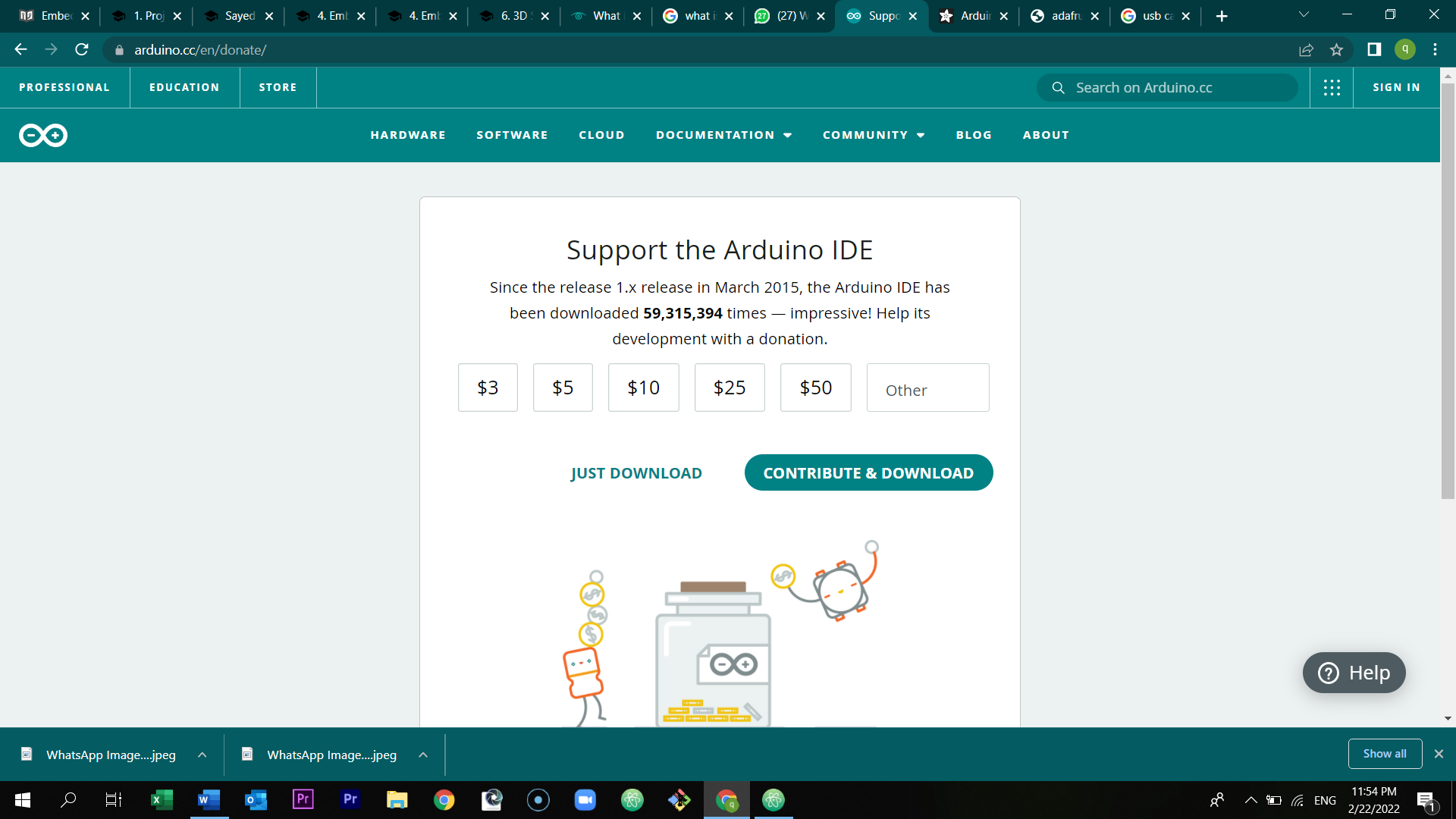
click yes.
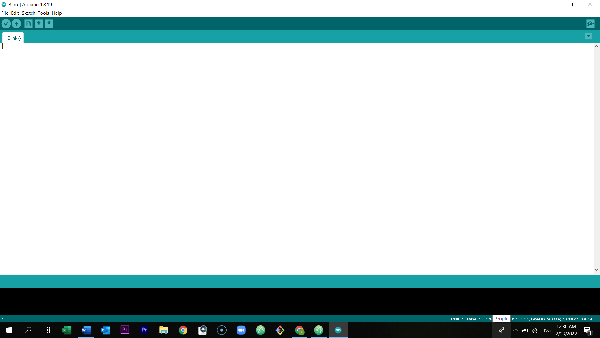
Once you locate the software in your desktop or anywhere else, open the program.
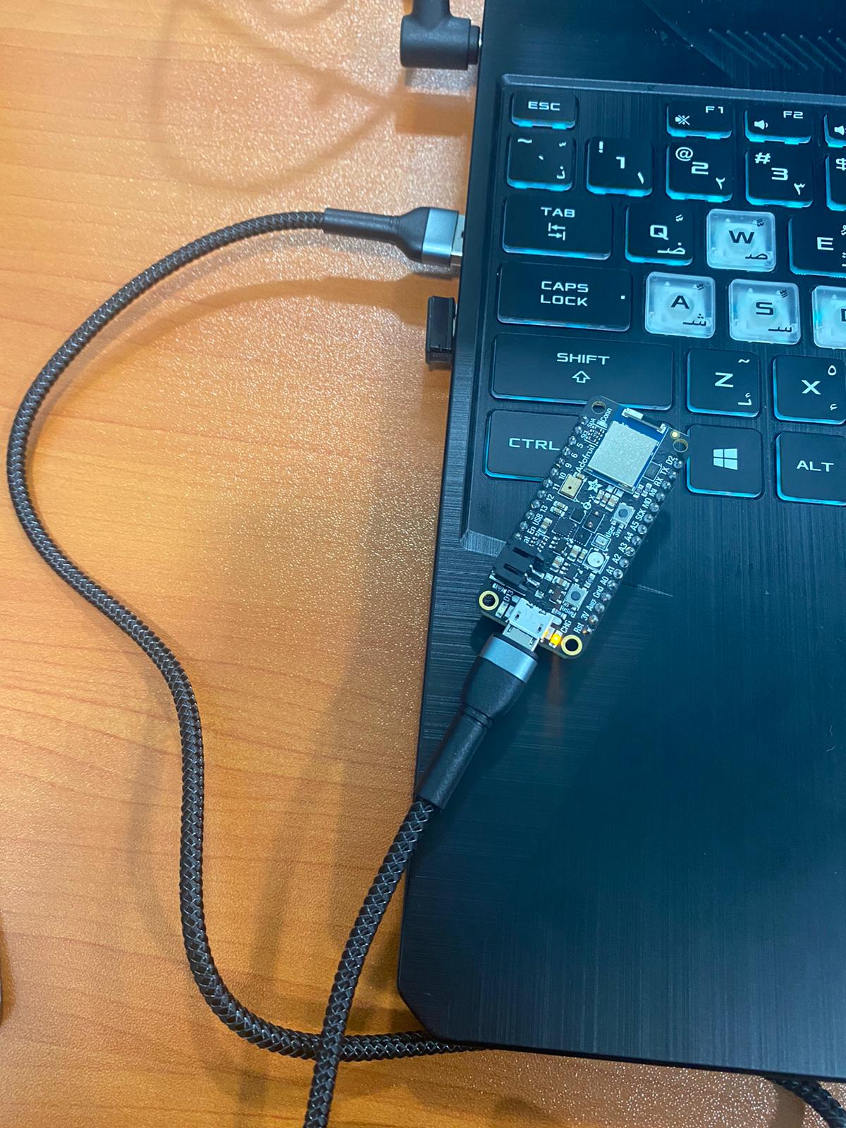
Then, connect the Adafruit Feather nRF52840 Sense to your laptop.
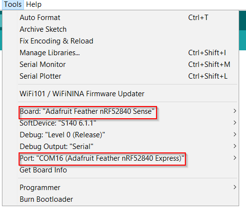
Click at tools, and make sure that these options are selected in board and port.
The process I have used to program the board
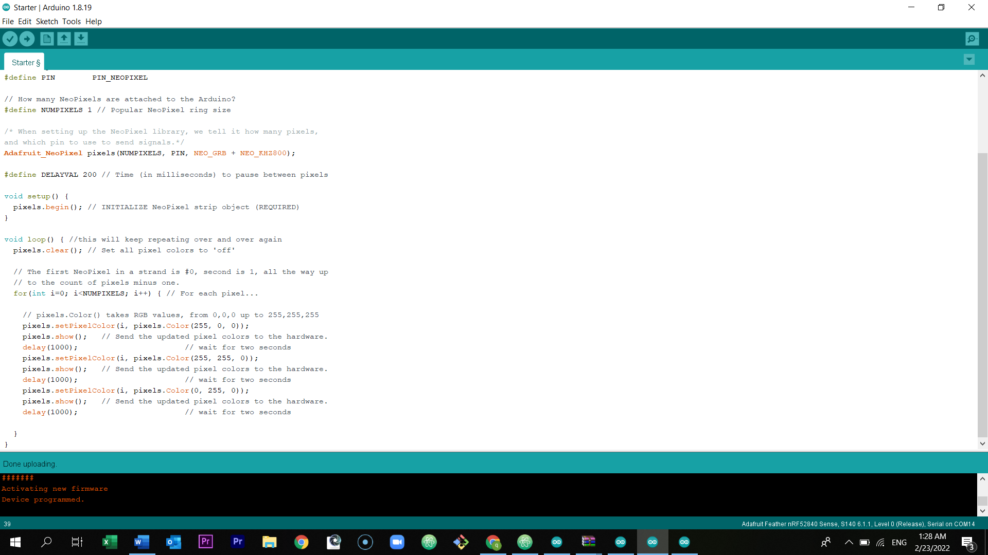
After connecting the microcontroller to your laptop, and made sure of the board and the port, put the code.
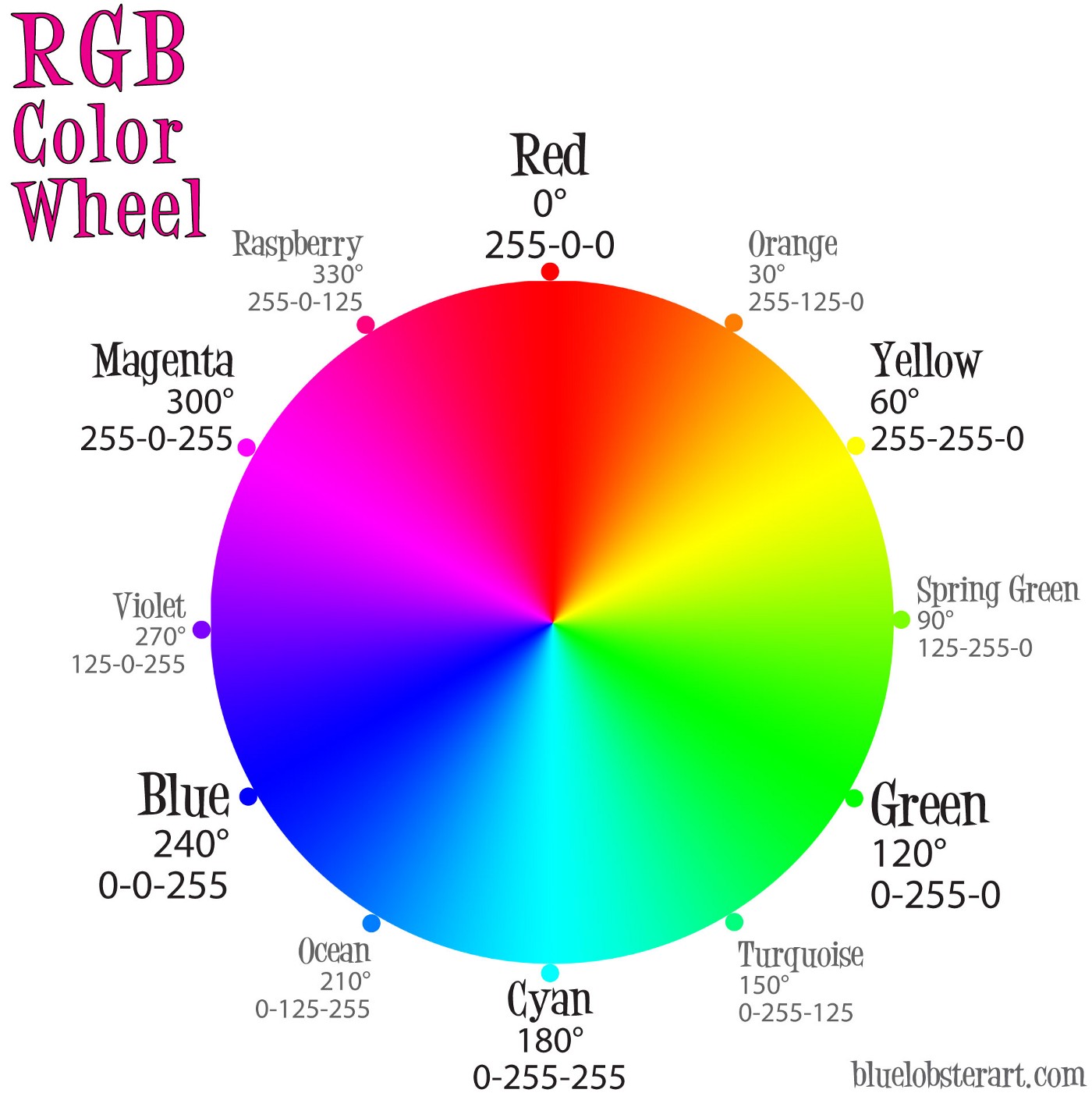
I programmed my board to the colors of the traffic light. I have done this by searching and reading in google, I have look into many websites and the most important one was this website. In addition, the codes in Sayed Hussain’s website helped me a lot too. I have used them and adjusted the time period and the colors using RGB color codes.
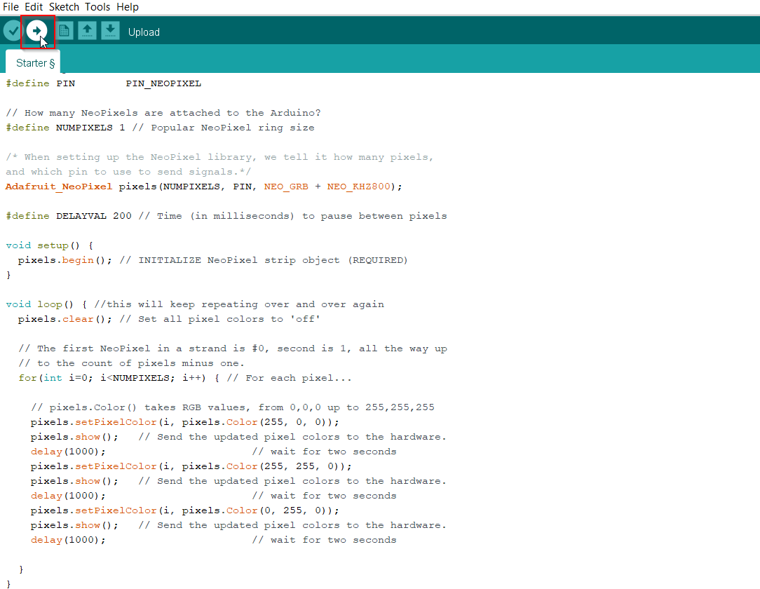
After inserting the codes, click at upload.
Source Code of the traffic light
// Done with Major help from this link: https://create.arduino.cc/projecthub/robocircuits/neopixel-tutorial-1ccfb9

/* Importing the Library */
#include <Adafruit_NeoPixel.h>
#ifdef __AVR__
 #include <avr/power.h> // Required for 16 MHz Adafruit Trinket
#endif

// Which pin on the Arduino is connected to the NeoPixels?
#define PIN        PIN_NEOPIXEL

// How many NeoPixels are attached to the Arduino?
#define NUMPIXELS 1 // Popular NeoPixel ring size

/* When setting up the NeoPixel library, we tell it how many pixels,
and which pin to use to send signals.*/
Adafruit_NeoPixel pixels(NUMPIXELS, PIN, NEO_GRB + NEO_KHZ800);

#define DELAYVAL 200 // Time (in milliseconds) to pause between pixels

void setup() {
  pixels.begin(); // INITIALIZE NeoPixel strip object (REQUIRED)
}

void loop() { //this will keep repeating over and over again
  pixels.clear(); // Set all pixel colors to 'off'

  // The first NeoPixel in a strand is #0, second is 1, all the way up
  // to the count of pixels minus one.
  for(int i=0; i<NUMPIXELS; i++) { // For each pixel...

    // pixels.Color() takes RGB values, from 0,0,0 up to 255,255,255
    pixels.setPixelColor(i, pixels.Color(255, 0, 0));
    pixels.show();   // Send the updated pixel colors to the hardware.
    delay(3000);                       // wait for two seconds
    pixels.setPixelColor(i, pixels.Color(255, 255, 0));
    pixels.show();   // Send the updated pixel colors to the hardware.
    delay(2000);                       // wait for two seconds
    pixels.setPixelColor(i, pixels.Color(0, 255, 0));
    pixels.show();   // Send the updated pixel colors to the hardware.
    delay(3000);                       // wait for two seconds

  }
}
Preview the short hero video of the board (Traffic Light)
Tinkercad and Morse code
The medium challenge was to pre code your microcontroller to send a Morse code 1 word message and challenge a friend, family member, your colleagues or your instructor to figure it out.
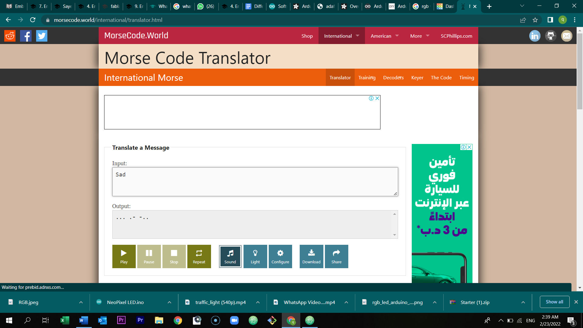
First of all, open the morse code translator. Then, write any one word message. You will then get the output morse code. To translate it and program it in tinkercad bare in mind that:
-
dot = 0.5 second light on.
-
dash= 1 second light on.
-
Gap between dots and dashes= 0.5 seconds light off.
-
gap between letters= 2 second light off.
After that, open tinkercad.
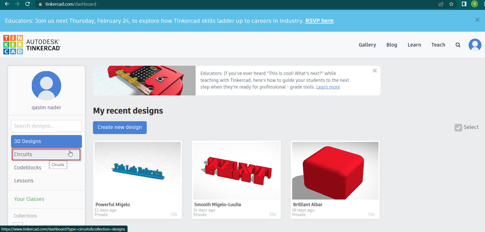
Click at circuits and select create a new circuit
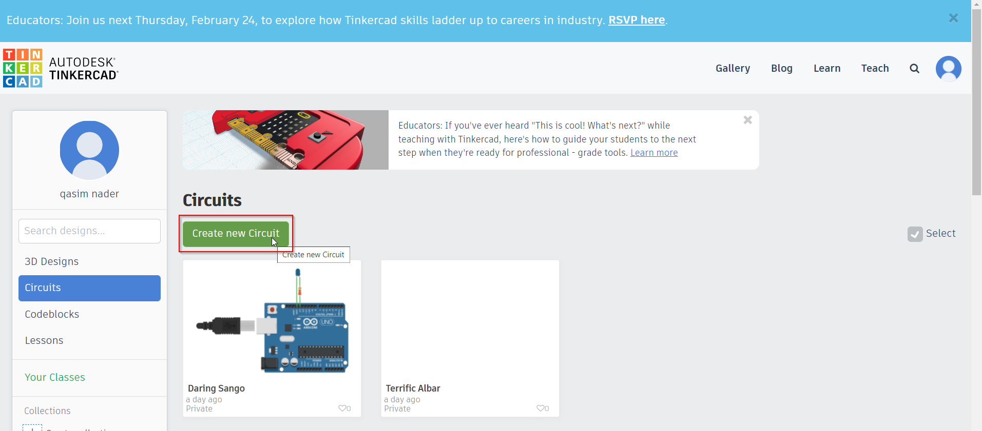
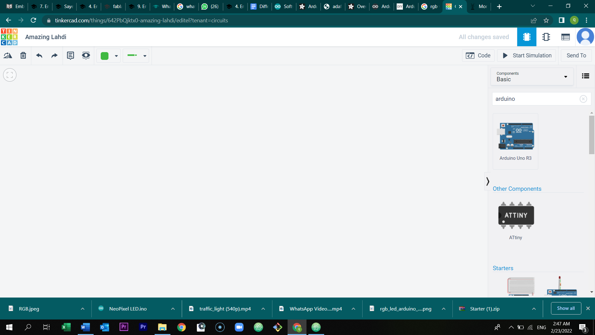
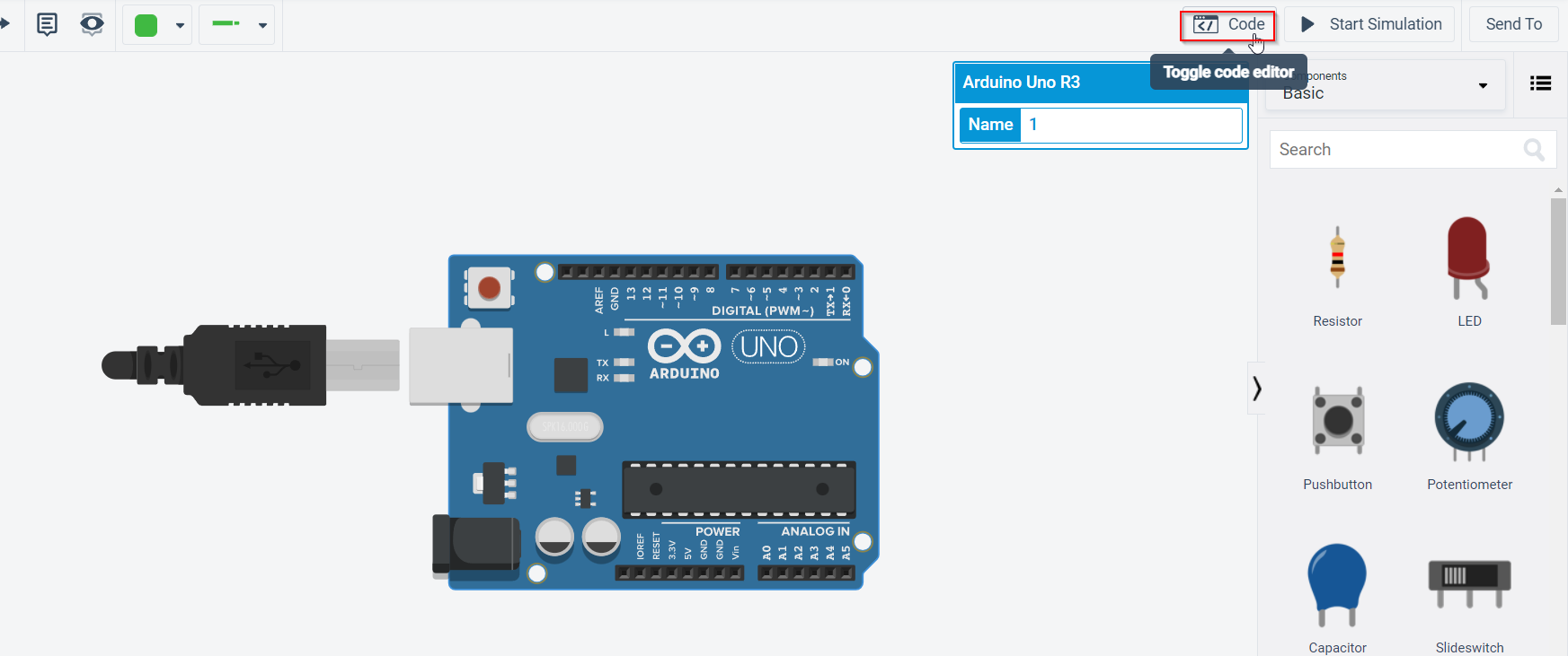
Type Arduino the search bar, and select the Arduino Uno R3.
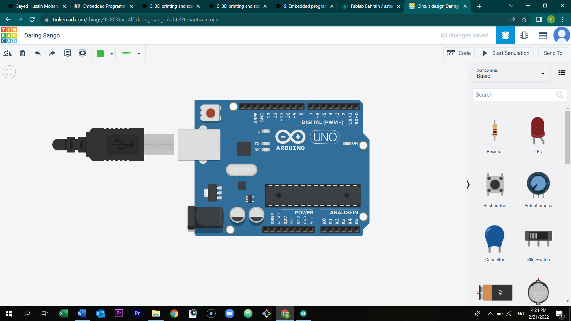
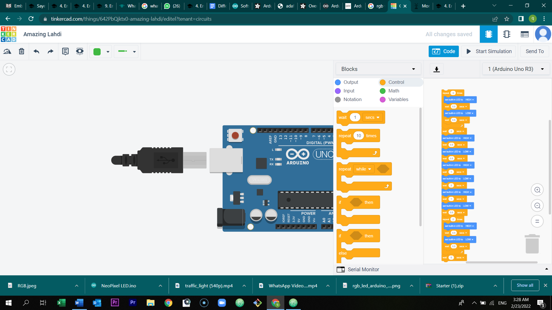
Select code.
This is my blocks code
Preview the video and try to determine the word.
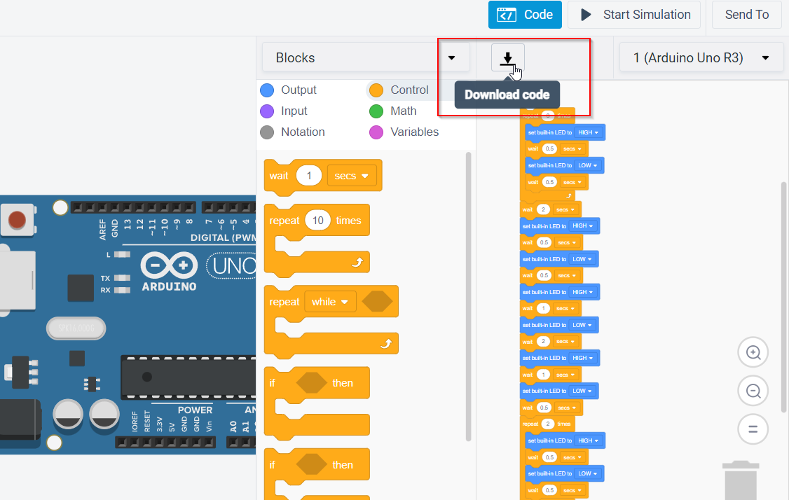
After that, I took the code in the tinkercad and I applied it in Arduino software. Click at download code and open the downloaded file.
Connect the microcontroller and upload the code in the device.
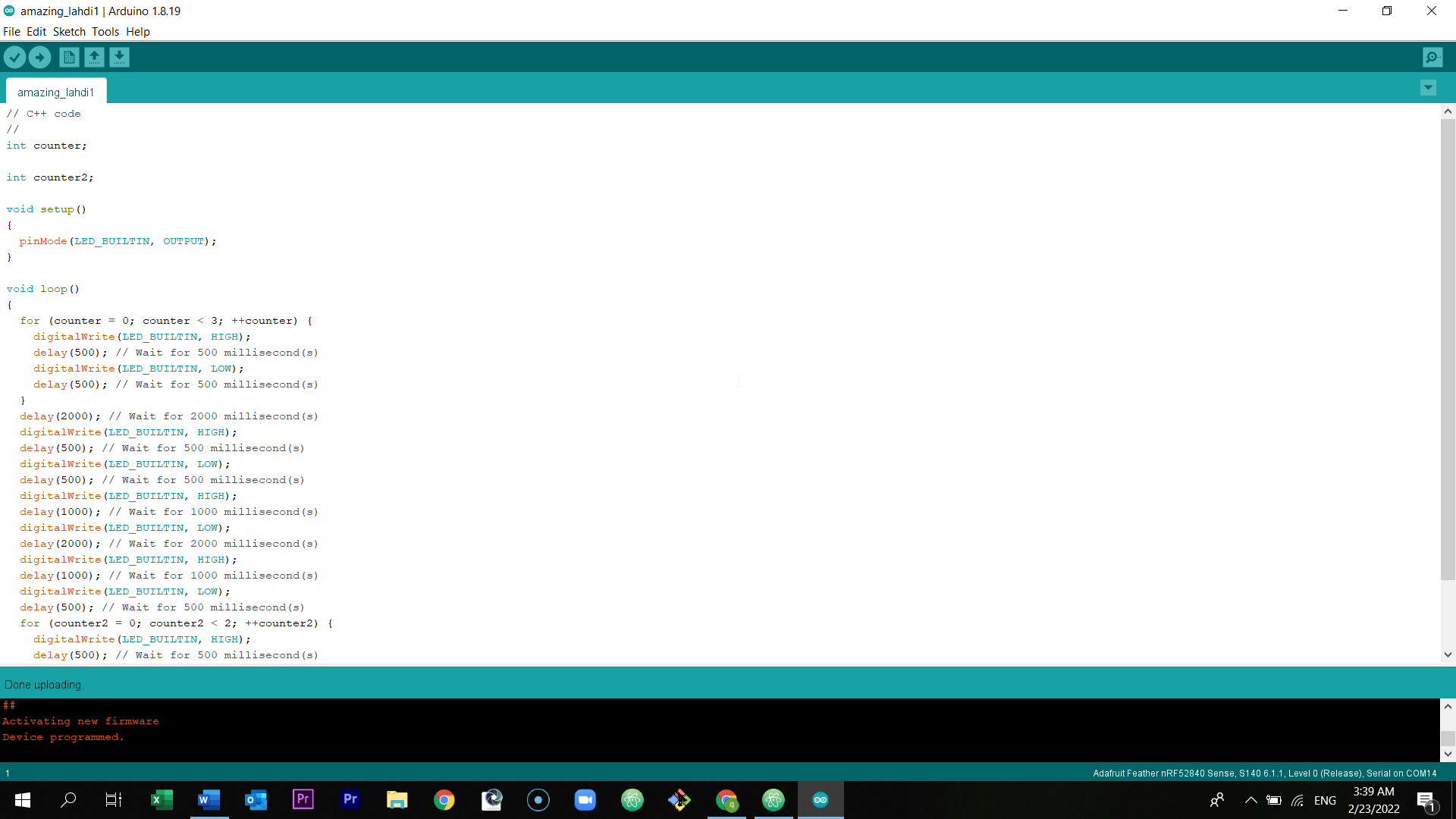
Source code of the morse code
// C++ code
//
int counter;

int counter2;

void setup()
{
  pinMode(LED_BUILTIN, OUTPUT);
}

void loop()
{
  for (counter = 0; counter < 3; ++counter) {
    digitalWrite(LED_BUILTIN, HIGH);
    delay(500); // Wait for 500 millisecond(s)
    digitalWrite(LED_BUILTIN, LOW);
    delay(500); // Wait for 500 millisecond(s)
  }
  delay(2000); // Wait for 2000 millisecond(s)
  digitalWrite(LED_BUILTIN, HIGH);
  delay(500); // Wait for 500 millisecond(s)
  digitalWrite(LED_BUILTIN, LOW);
  delay(500); // Wait for 500 millisecond(s)
  digitalWrite(LED_BUILTIN, HIGH);
  delay(1000); // Wait for 1000 millisecond(s)
  digitalWrite(LED_BUILTIN, LOW);
  delay(2000); // Wait for 2000 millisecond(s)
  digitalWrite(LED_BUILTIN, HIGH);
  delay(1000); // Wait for 1000 millisecond(s)
  digitalWrite(LED_BUILTIN, LOW);
  delay(500); // Wait for 500 millisecond(s)
  for (counter2 = 0; counter2 < 2; ++counter2) {
    digitalWrite(LED_BUILTIN, HIGH);
    delay(500); // Wait for 500 millisecond(s)
    digitalWrite(LED_BUILTIN, LOW);
    delay(500); // Wait for 500 millisecond(s)
  }
  delay(5000); // Wait for 5000 millisecond(s)
}
Preview the short hero video of the board (Morse code)
Group assignment
- The first group assignment can be found here:
Click at the sources to read more:
- The second group assignment can be found in Zainab’s Website