7. Input & Output device
This week we started working on input and output devices.
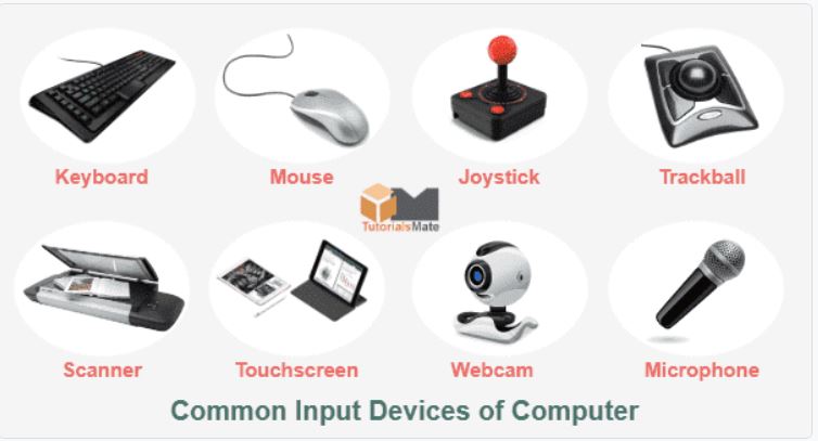
What is input device?
In computing, an input device is a piece of equipment used to provide data and control signals to an information processing system, such as a computer or information appliance. Examples of input devices include keyboards, mouse, scanners, cameras, joysticks, and microphones.
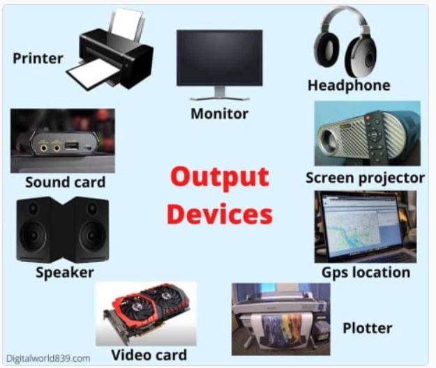
What is Output device?
An output device is any piece of computer hardware equipment which converts information into a human-perceptible form or, historically, into a physical machine-readable form for use with other non-computerized equipment. It can be text, graphics, tactile, audio, or video.
Sensor.
A sensor is a device that produces an output signal for the purpose of sensing a physical phenomenon. In the broadest definition, a sensor is a device, module, machine, or subsystem that detects events or changes in its environment and sends the information to other electronics, frequently a computer processor.
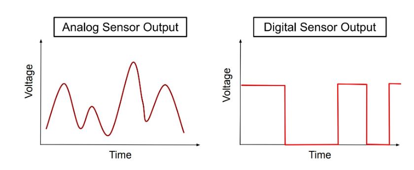
Analog Sensors
Analog Sensors measure the external parameters and give an analog voltage as an output. They produce a continuous output signal or voltage which is proportional to the quantity being measured. The output voltage may be from the range of 0 to 5V. Low logic 0 (0V-3.5V) and High logic (3.5V-5V).
Digital sensors
A digital sensor is an electronic or electrochemical sensor, where data is digitally converted and transmitted. Sensors are often used for analytical measurements, e.g. the measurement of chemical and physical properties of liquids
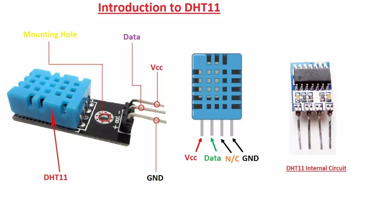
DHT11–Temperature and Humidity Sensor.
As we are working with input and output devices i chose DHT11–Temperature and Humidity Sensor to work on it with microcontroller. - DHT11–Temperature and Humidity Sensor a basic, ultra low-cost digital temperature and humidity sensor. It uses a capacitive humidity sensor and a thermistor to measure the surrounding air, and spits out a digital signal on the data pin (no analog input pins needed). Its fairly simple to use, but requires careful timing to grab data.
- Specifications:
- 3 to 5V power and I/O
- 2.5mA max current use during conversion (while requesting data)
- Good for 20-80% humidity readings with 5% accuracy
- Good for 0-50 °C temperature readings +-2 °C accuracy
- No more than 1 Hz sampling rate (once every second)
- Body size 15.5mm x 12mm x 5.5mm
- 4 pins with 0.1" spacing
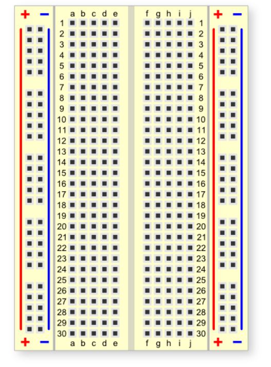
Stripboard.
Stripboard is the generic name for a widely used type of electronics prototyping material for circuit boards characterized by a pre-formed 0.1 inches regular grid of holes, with wide parallel strips of copper cladding running in one direction all the way across one side of on an insulating bonded paper board.
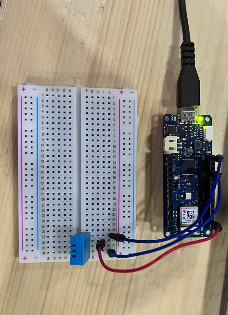
Connecting HDT11 Sensor.
We were asked to connect the sensor with microcontroller and run the microcontroller for the results so for good connection without any mistake i nevigated to a website from where i got the idea of correct connection. I set pin 7 for the data signal and connected ground and voltage.
Adding Library on Arduino.
After connecting the sensor to the microcontroller with use of stripboard i started adding a code and Library on ardunio software to get positive results.I nevigated to this website from where i downloaded Library. To upload i went to Sketch>Include Library>Add .ZIP Library and select the DHTLib.zip file.

Adding Code on Arduino.
After uploading Library i nevigated in the same website copy the code. After pasting the code in Arduino software i compiled the code.
Modifications
I modified the pin number according to my Microcontroller and connections i connected.
- Note. as i set pin 7 for data signal i used the following code.
 #include <dht.h>

dht DHT;

#define DHT11_PIN 7

void setup(){
  Serial.begin(9600);
}

void loop(){
  int chk = DHT.read11(DHT11_PIN);
  Serial.print("Temperature = ");
  Serial.println(DHT.temperature);
  Serial.print("Humidity = ");
  Serial.println(DHT.humidity);
  delay(2000);
}
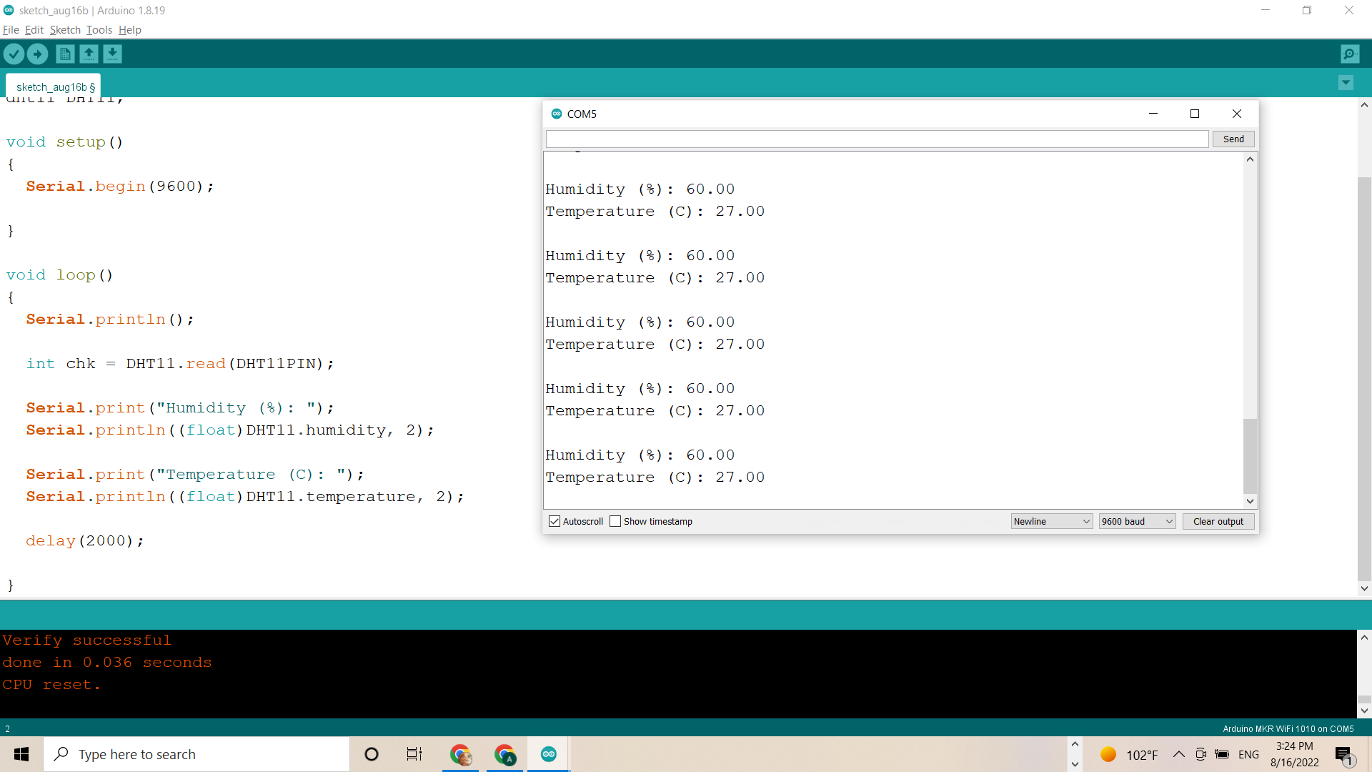
Result.
After uploading compiling the code i got the following result on serial monitor.
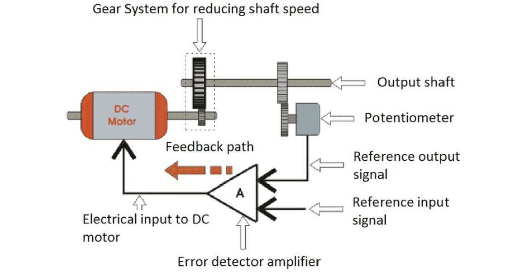
Servo Motor.
This week we also started working on Servo motor.
- Micro Servo Motor SG90 is a tiny and lightweight server motor with high output power. Servo can rotate approximately 180 degrees (90 in each direction), and works just like the standard kinds but smaller. You can use any servo code, hardware or library to control these servos.

Functions
Servos are controlled by sending an electrical pulse of variable width, or pulse width modulation (PWM), There is a minimum pulse, a maximum pulse, and a repetition rate. A servo motor can usually only turn 90° in either direction for a total of 180° movement.
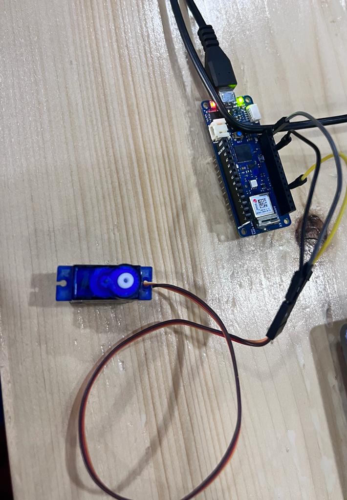
Conecting Servo motor.
After getting my Servo motor i started setting connections with microcontroller i set the shaft of a RC servo motor back and forth across 180 degrees.To do so, join pins 9, GND, and +5V on the servo motor. Power, ground, and signal wires are all that servo motors have. It is recommended to attach the power line, which is normally red, to the Arduino board’s 5V pin. It is recommended to attach the ground wire, which is normally black or brown, to a ground pin on the circuit board. It is recommended to link the board’s PWM pin to the signal pin, which is commonly yellow or orange. The pin number in this instance is 9.
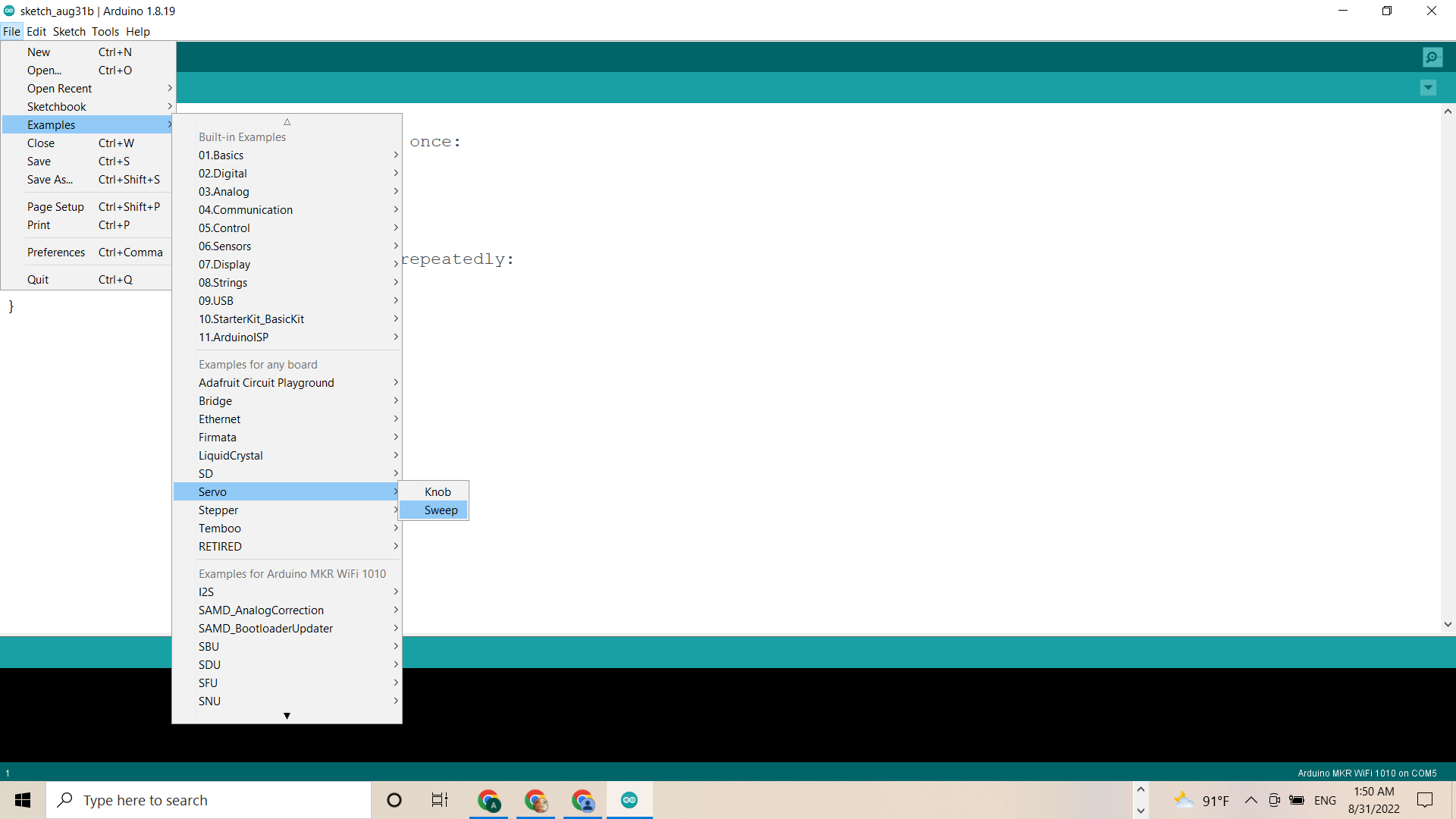
Compiling the Code.
After setting the connection with microcontroller i connected the microcontroller through USB cable and started compiling before compiling i went through some steps to add the code of servo motor on Arduino Software.(The steps are File-> examples-> servo-> Sweep.) After compiling i was able to run the servo motor. The steps are shown in picture below.
Sweep Code
After compiling the following code the servo motor starts moving According to the code.
Modification.
In this code i changed the time and the Rotating direction of Servo in degres.
 /* Sweep
 by BARRAGAN <http://barraganstudio.com>
 This example code is in the public domain.
 modified 8 Nov 2013
 by Scott Fitzgerald
 https://www.arduino.cc/en/Tutorial/LibraryExamples/Sweep
*/
#include <Servo.h>
Servo myservo;  // create servo object to control a servo
// twelve servo objects can be created on most boards
int pos = 0;    // variable to store the servo position
void setup() {
  myservo.attach(9);  // attaches the servo on pin 9 to the servo object
}
void loop() {
  for (pos = 0; pos <= 180; pos += 1) { // goes from 0 degrees to 180 degrees
    // in steps of 1 degree
    myservo.write(pos);              // tell servo to go to position in variable 'pos'
    delay(15);                       // waits 15 ms for the servo to reach the position
  }
  for (pos = 180; pos >= 0; pos -= 1) { // goes from 180 degrees to 0 degrees
    myservo.write(pos);              // tell servo to go to position in variable 'pos'
    delay(15);                       // waits 15 ms for the servo to reach the position
  }
}
Result.
As we can see the result in the following video.
Group Assigment.
Hero shot
- Video
Remarks.
I gained control over servo motors and KY-009 RGB LED from completing these activities. By connecting output devices to the microcontroller, I also discovered that resistors may be necessary and how to use them. We ran into a problem where the KY-009 RGB Led would only produce a red light, as I indicated before. We experimented with various codes and made changes to them because we believed there might be some issues with them. As a result, we become familiar with a variety of codes and how they operate.
Problems and solutions.
In starting i faced problems with microcontroller as it was showing the port missing after i asked one of my instructor and i came over and also i faced issue with the sensor isntalling and also i was not able to program the sensor to make it work so i asked one on my collegue and she helped me out to find the solution.
Useful links
- Humidity & Temperature sensor
- Servo motor
- Servo motor working principle
- Analog Sensor
- Digital sensor