6. Large format CNC (computer controlled Machining)
This week we start working on CNC (computer controlled Machining).
CNC (computer controlled Machining).
Numerical control is the automated control of machining tools by means of a computer. A CNC machine processes a piece of material to meet specifications by following coded programmed instructions and without a manual operator directly controlling the machining operation.Read More
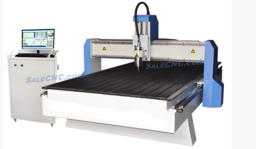
How Do CNC Machines Work?
CNC machines usually feature a version of a CAD software program. A CAD program, or computer-aided design, is software which allows you to draw what you want to cut. The drawing is either 2D or 3D and when completed it a creates a code for the CNC machine to read. CNC machines work by following co-ordinates along axis. Basic machines move along one or two axis, but advanced machines, and those creating 3D items, will move along three axis. The machine’s tools follow thousands of co-ordinates, cutting and shaping as they move. Before a CNC machine begins its first task, a trial run is conducted. This trial run is referred to as cutting air and is incredibly important as any mistakes could result in a damaged machine or part.
Group Assignment
- Group Assignment link
- After working in group i understod the working way of cnc and i got lot of information about CNC Which made it easy for me to do my individual project.
Individual Assignment.(Something big)
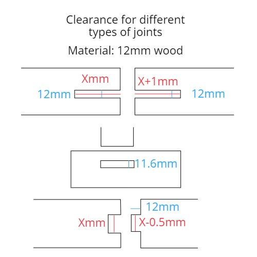
After Completing my group assignment we were asked to chose a design (Which should be somthing big) for our individual assignment which i will be working on it using fusion 360 software and also i will cut it on CNC Machine.We also got the idea of joints and their sizes.
- Joint Tolerance
Chosing Design.
After we were asked i nevigated to some websites so that i can choose a design for my individual assignment i entered in to This website from where i chose my design for individual assignment.
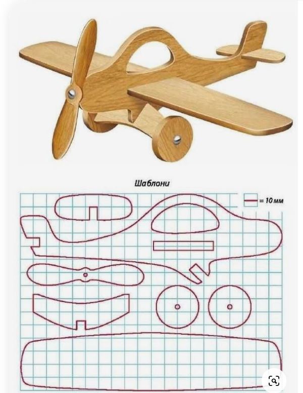
My Design.
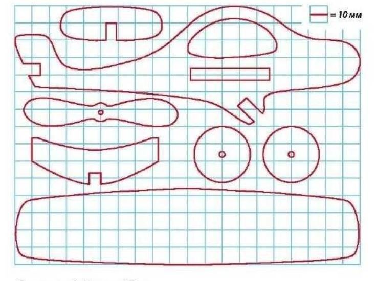
I chose a toy aircraft as a design for my individual assignment. We can see the picture shown below.
 - Orignal design link
Source.
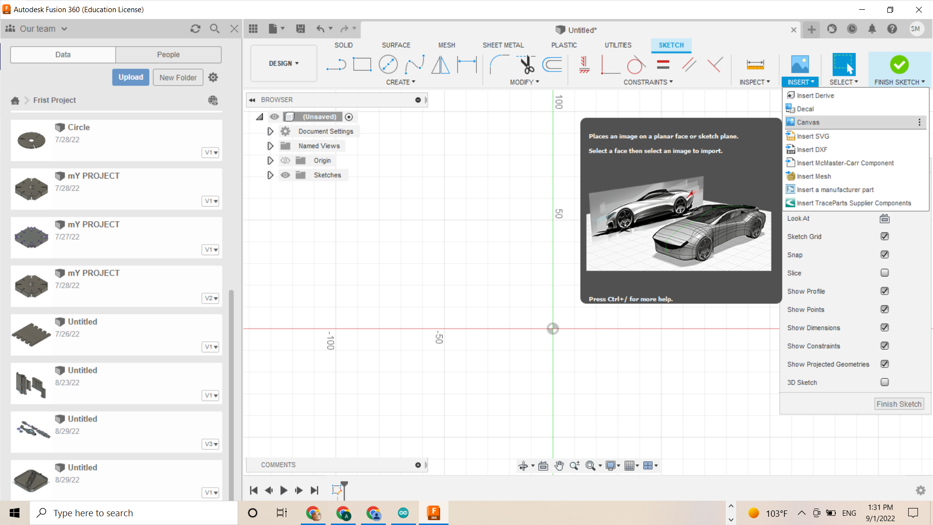
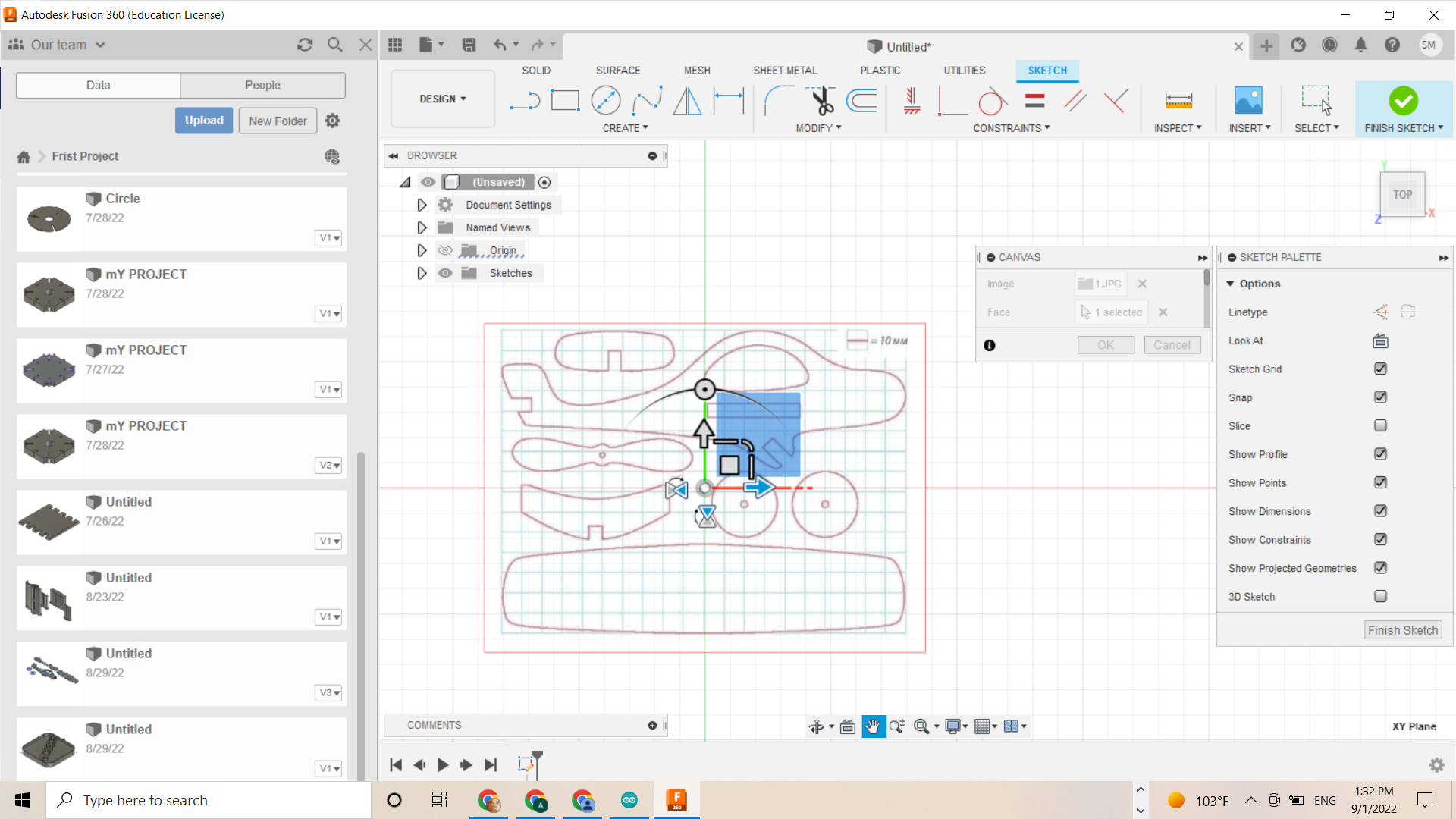
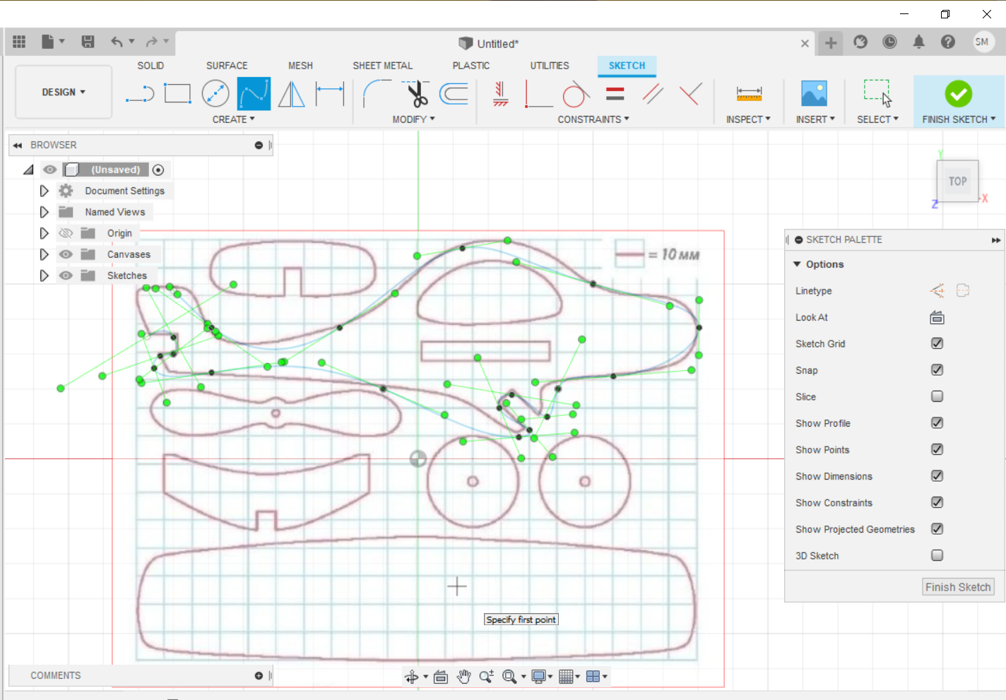
After chosing my design i started working on it using fusin 360 software. I chose the picture as Source to start my design. I started using canvas option to upload the source on fusion 360.We can see the process shown in pictures below.
Creating design.
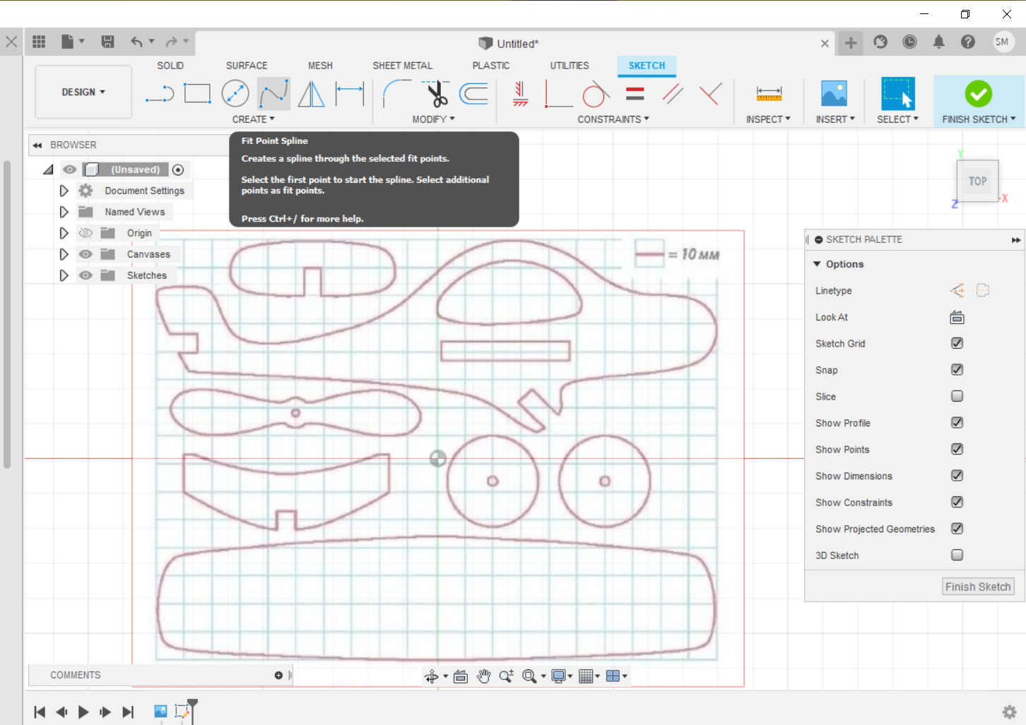
After importing the source(Image) in to fusion 360 i started working on design using fit point spline option. The fit point spline makes a smooth curve that traverses a number of points; therefore, i clicked each point that i needed the spline to contact.We can see the process shown in pictures below.
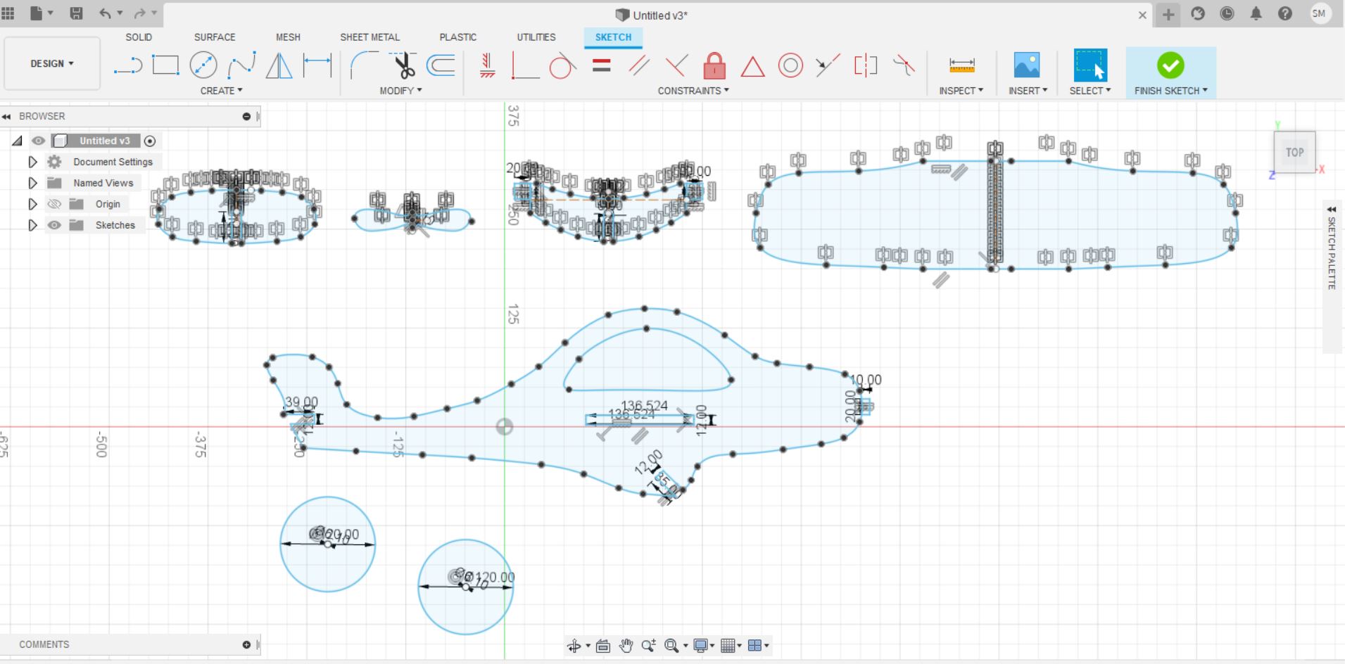
Modifying the design.
After Completing from fit point spline process i start working to do some changes and modify the design. and i also set all the joints parametrically so my design can fix properly with parametric joints.
Sending Files to CNC.
After compleating my design i saved my design in dxf formate and i sent the file to CNC machine’s system through email to make them ready for cutting.
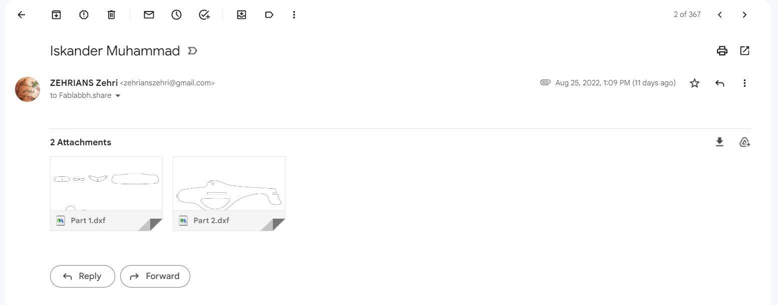
CNC System.
I started downloading dxf files from email in to CNC system and i started working on them in cnc system (Desktop).
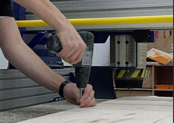
Cutting Phase.
Before starting the cutting operation, i had to make the wooden panel stable on cnc machine as we can see in pic below.
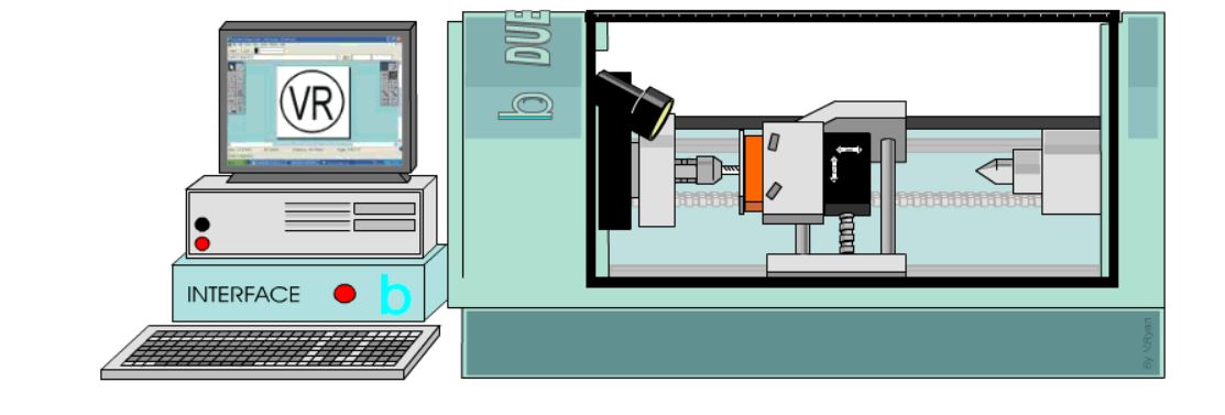
Alignment in cnc machine.
Most CNC equipment can benefit greatly from alignment for proper operation. A laser alignment system is the most accurate way to align CNC mills, lathes, and gantries if your goal is to ensure accuracy or simply to reduce machine tool wear. Workplace stress builds up as a result of alignment when setting up new machines, working on sub-assemblies, and even regular machine tool applications since the more duties you have, the more likely it is that you will make mistakes.While alignment and measurement projects may adhere to a well-thought-out alignment process, the machine you are working on has numerous components that must adhere to specifications in order to prevent errors. Additionally, if multiple people have access to your CNC machine, there is a greater risk that the machine will become out of alignment.
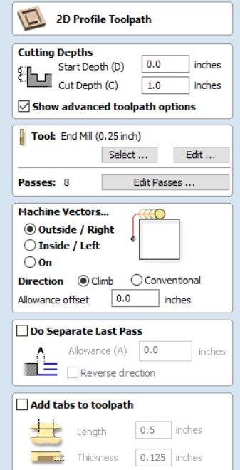
Toolpath profile.
In order to automatically account for the tool diameter and angle for the selected cut depth, profile toolpaths might be outside, inside, or on the vectors that have been chosen.Cutting around or along a vector is done using profile machining. With customizable Tabs and bridges and an Allowance over/undercut to guarantee precise edge quality, options give you the flexibility to cut out shapes.
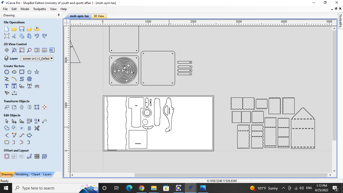
Toolpaths tab
After downloading the file on system i started editing the file on vCarve pro Application.on this stage we adjust the file on area of cnc machine which is depends on playwood dimensions is 1220mm x 2440mm x 12mm.Then i converted to Toolpaths tab.
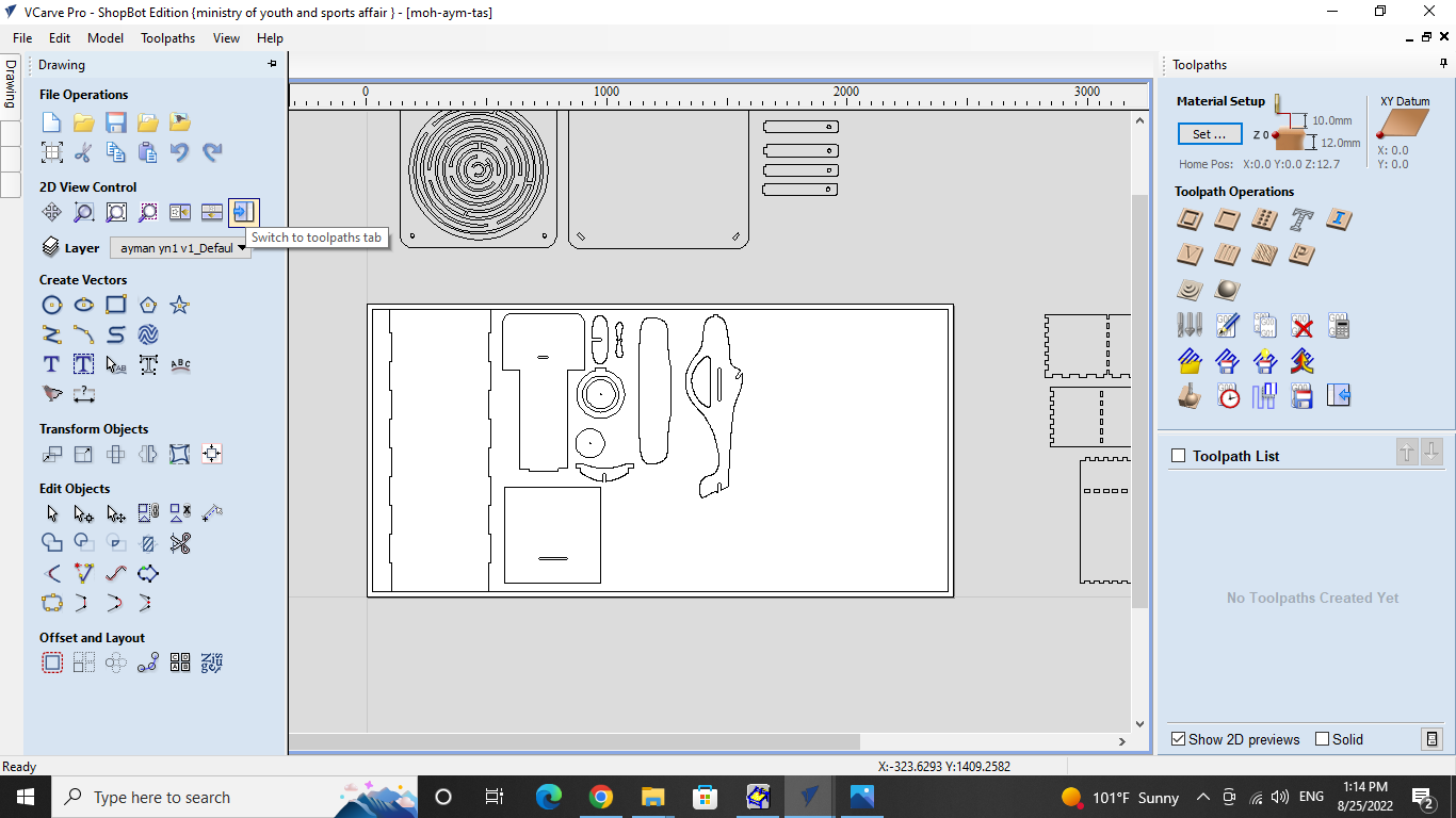
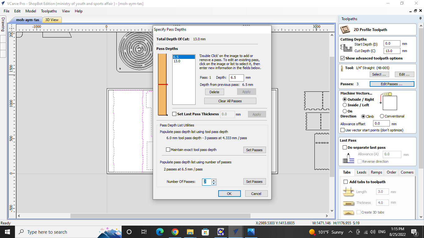
Tool info and depth values.
These values are necessary to cut plywood, which is described as having a cutting depth of 13 mm, a blade thickness of 3 mm, a moving blade head speed of 30 inches per minute, a feed rate of 110, and a blade rotation speed of 14000 revolutions per minute.
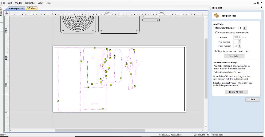
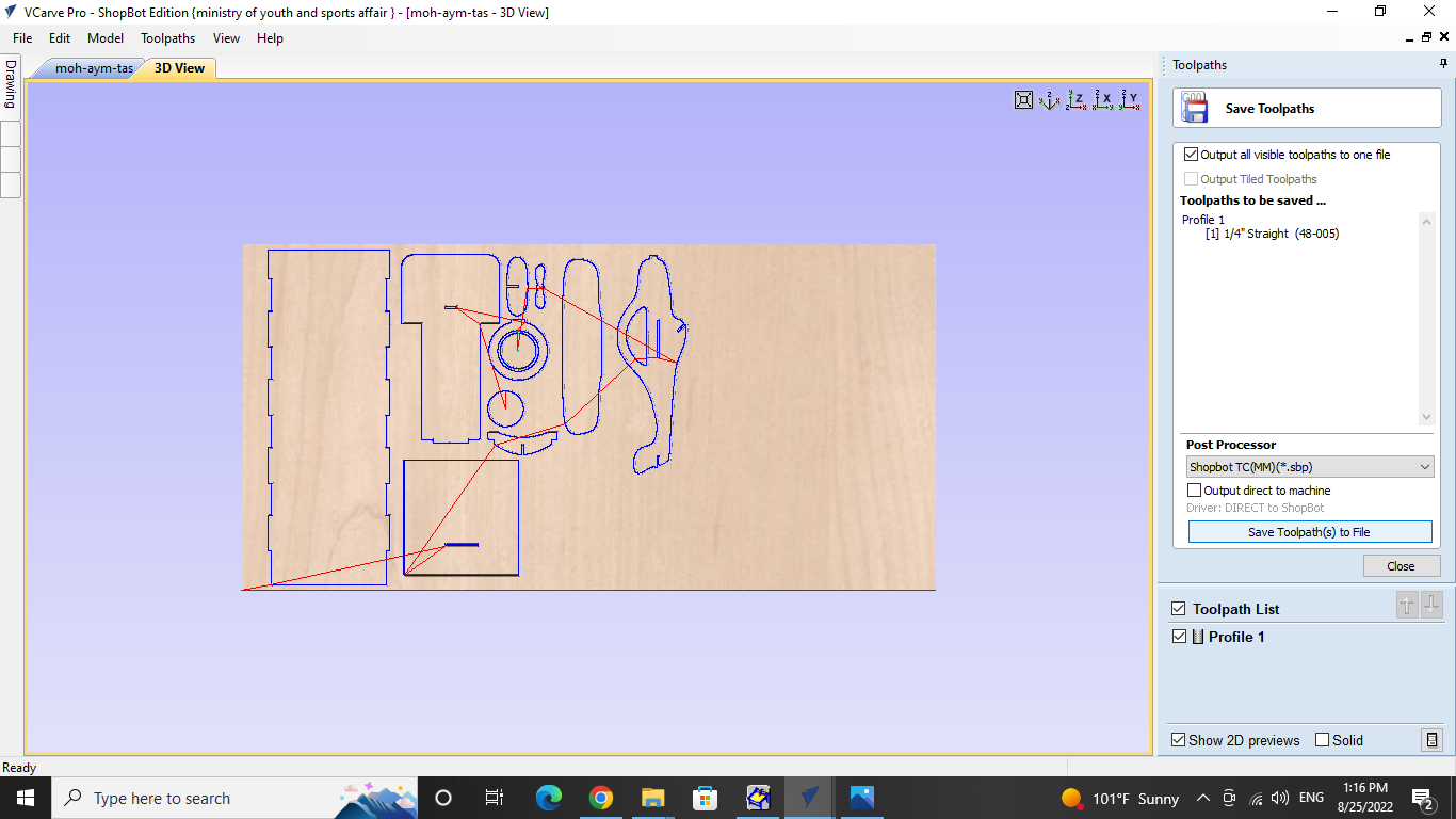
Tabs locations and preview of the toolpath.
Here where the tabs will be placed when cutting is taking place. The tabs will be used to keep the sections together and guard against anomalies we can see the tab location and also preview toolpath shown in the picture below.
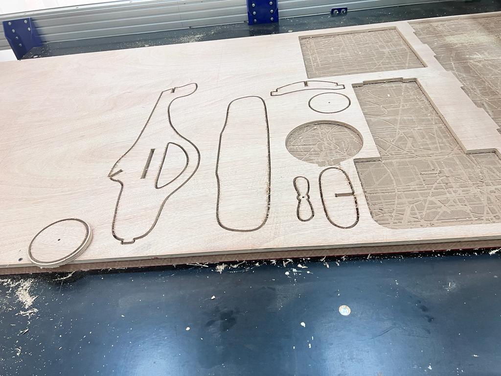
After Cutting.
After Setting and sending the file on to the CNC Machine it took almost 10 minutes to cut the design. So now my design is ready for Assemble.
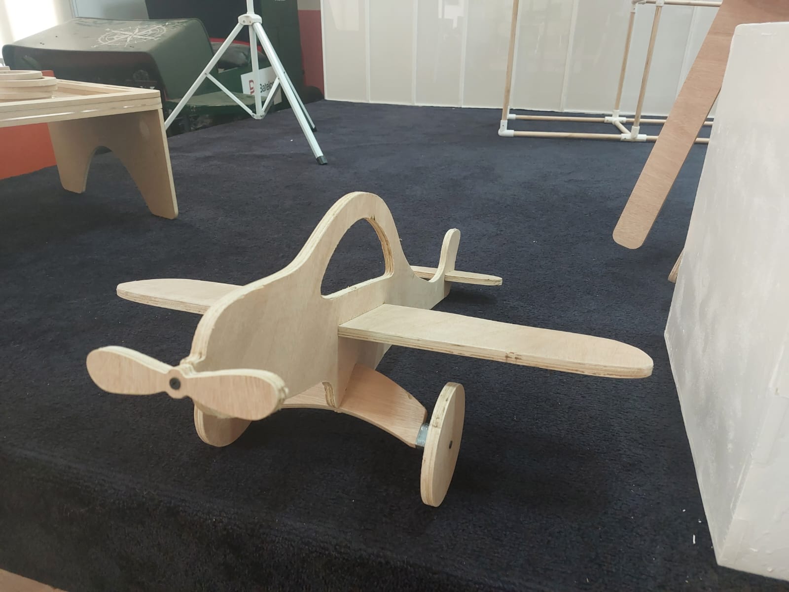
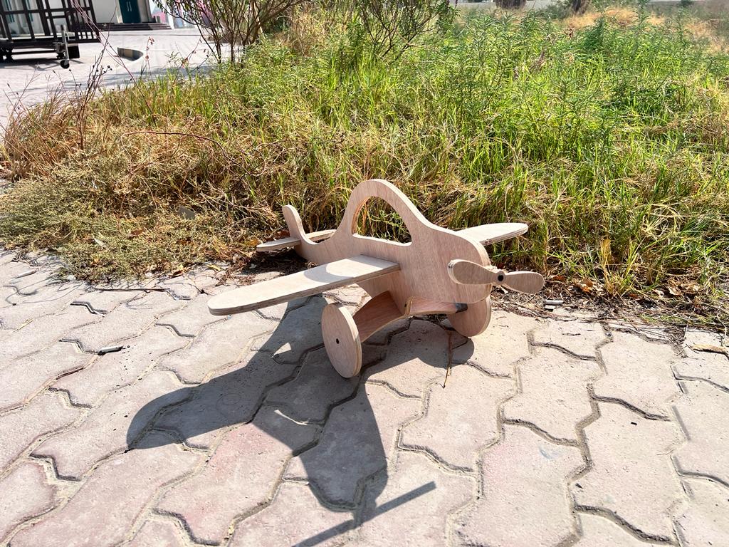
Final Result.
After completing from cutting i took my design and assembled the design with joints.We can see the results in pictures shown below.
Problems and their solutions.
I faced many problems during this assignment the frist problem was creating the design in wich i was not able to creat the joints parametrically so i asked one of my instructor and he gave me the idea.second problem was to use the cnc machine so help of my instructor i was able to use the CNC machine.