7. 3D printing and scanning
This week I worked on 3D printing and 3D scanning using several programs and for different applications.
3D Printing
Instrument
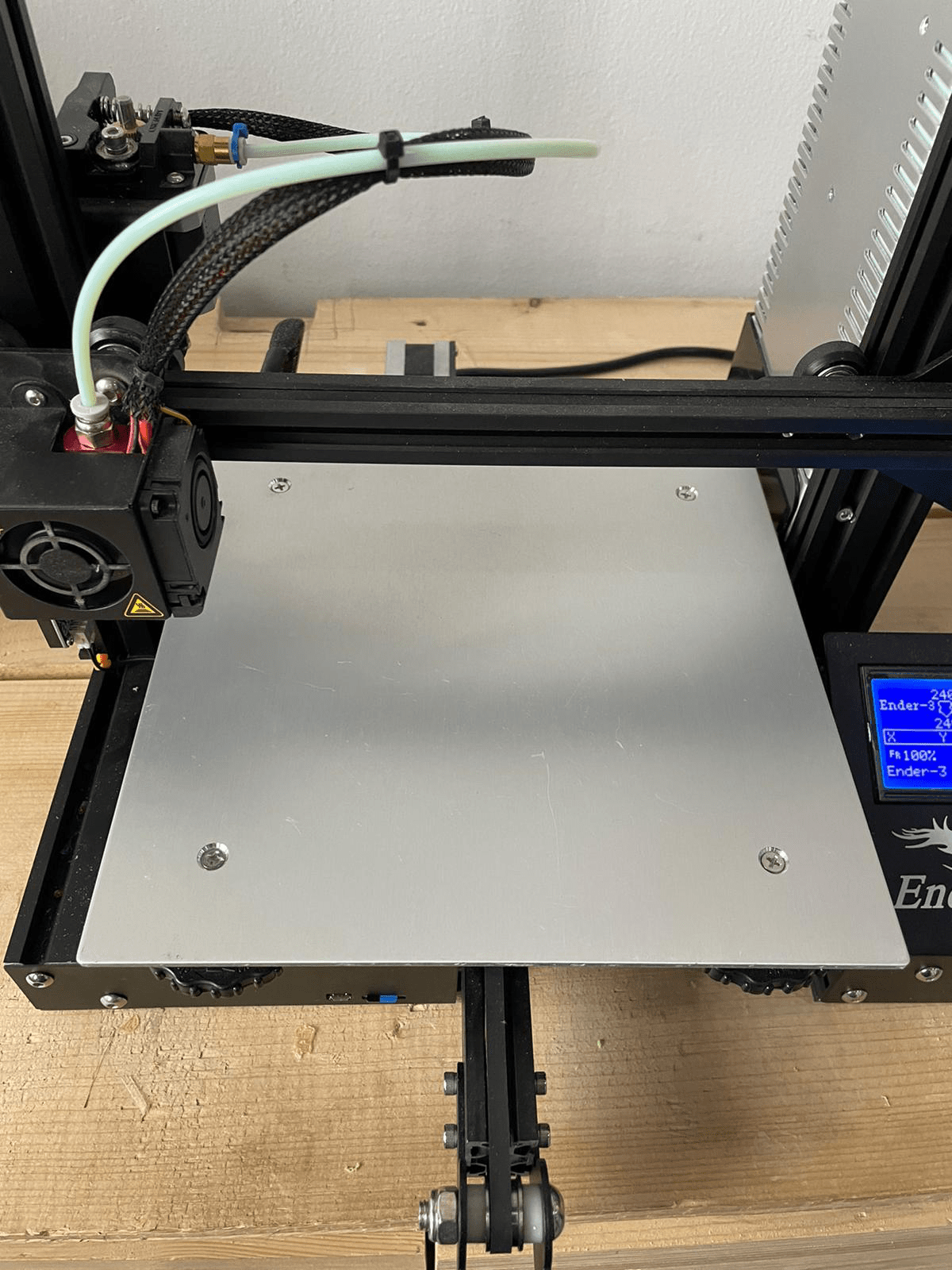
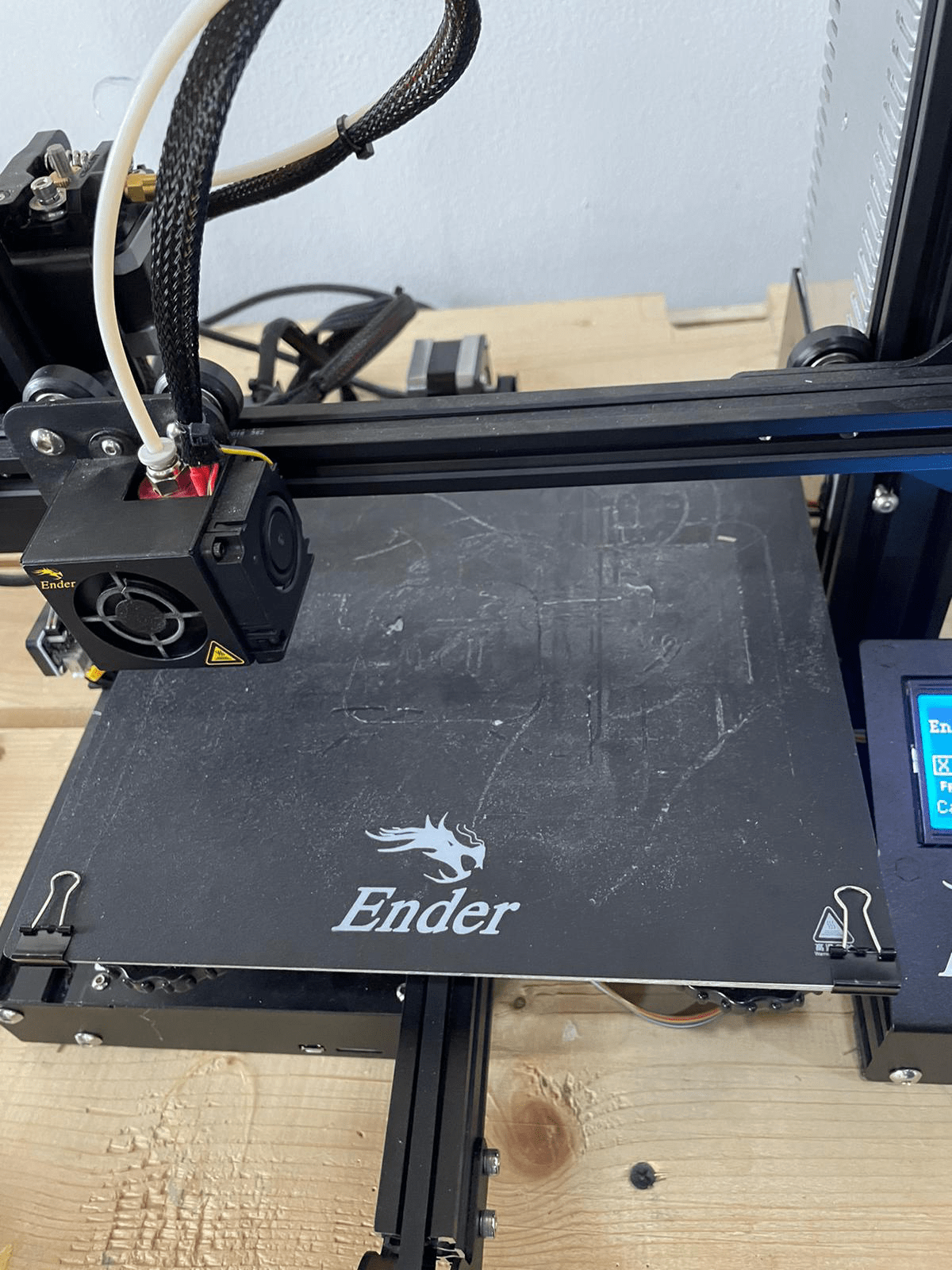
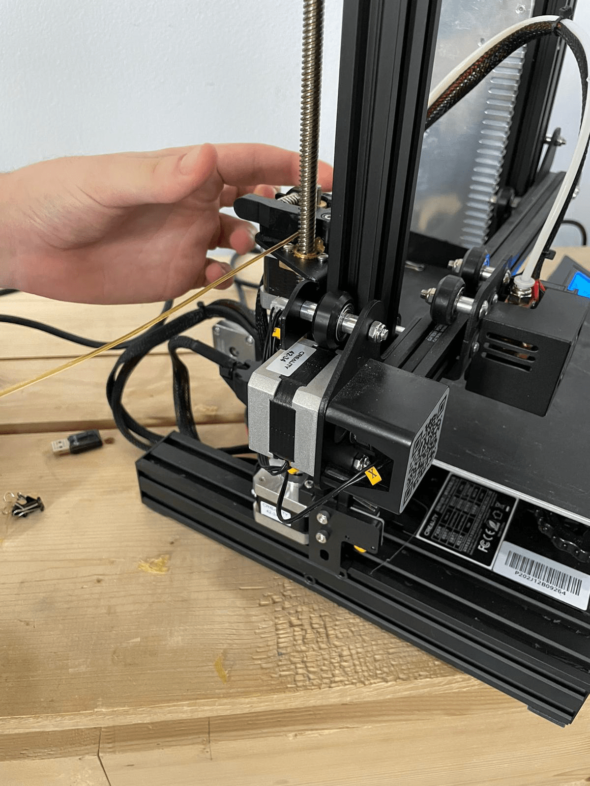
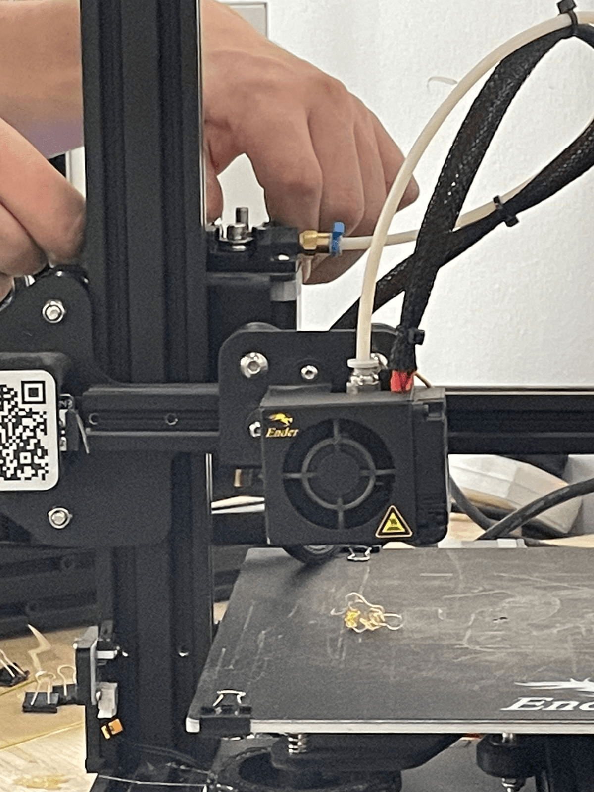
The instrument used for 3D printing is called Ender. The designed files were transferred to the instrument using a SD card. Some specification were identified. Such as layer height, speed and build plate adhesion type, etc. A flexible bed was fixed above the instrument surface with clips on the corner. The surface is heated uniformly to prevent any shrinkage due to sudden temperature change and to maintain the shape of the printed object.
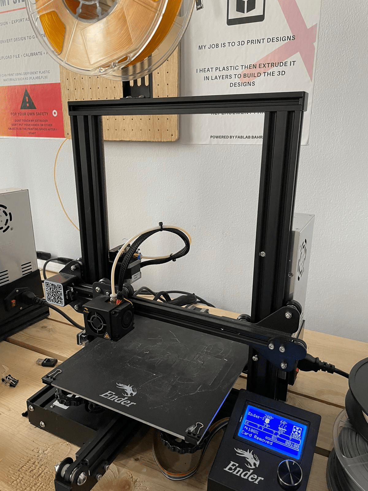
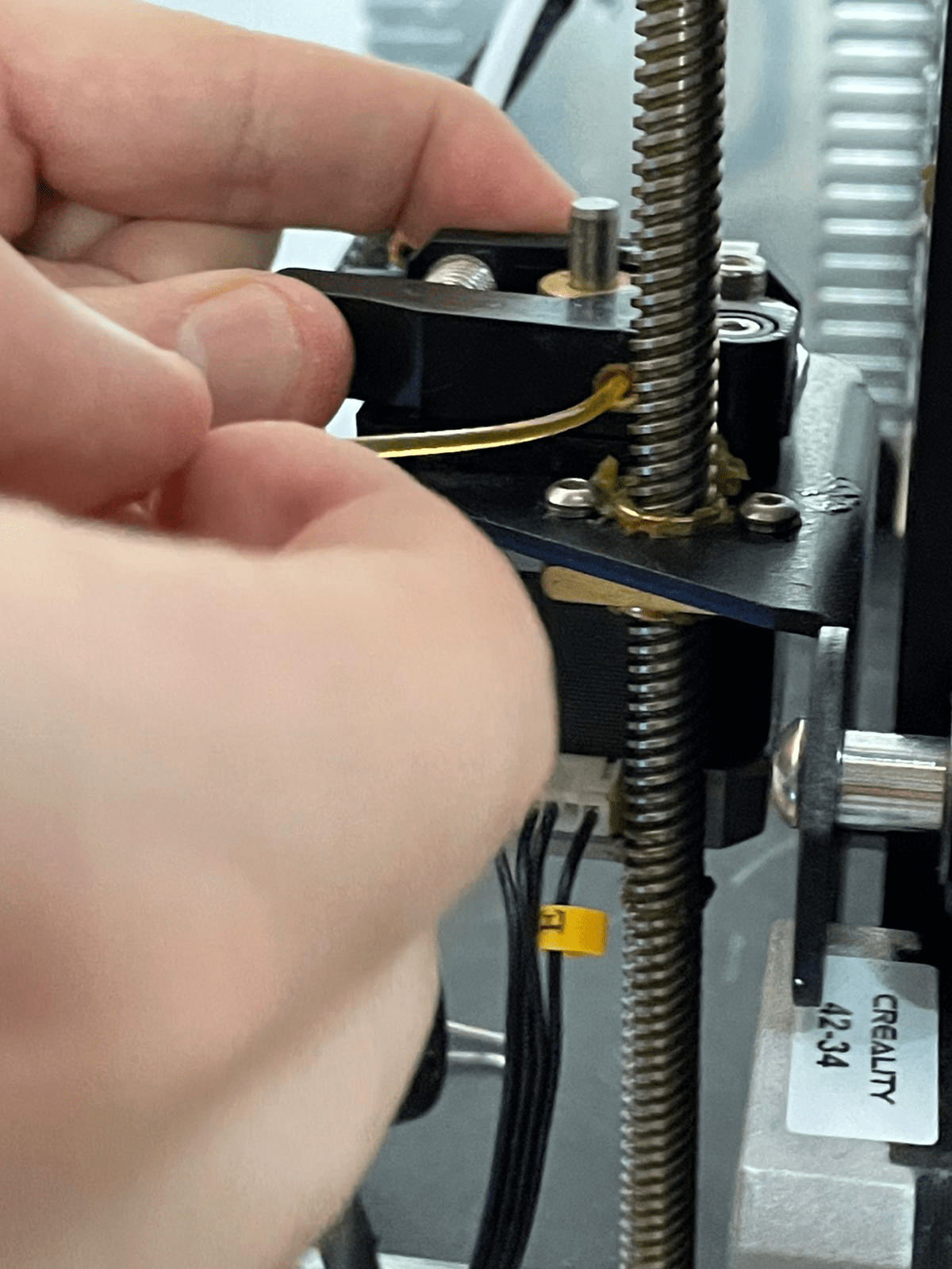
The desired material was attached to the instrument. A wire was introduced to the gap where the material is heated and melted to be formed to the desired design. Before printing the wire is pushed until some of it get out melted to make sure no air gaps while printing.
Design
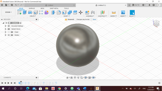
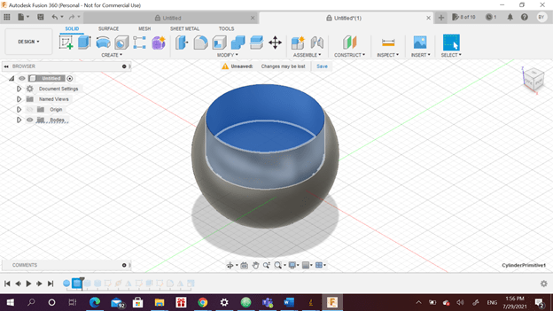
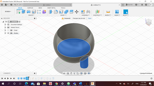
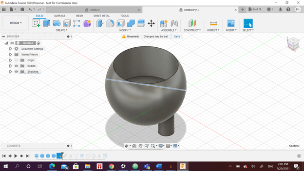
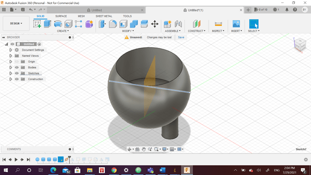
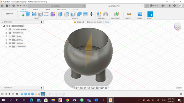
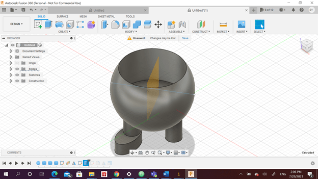
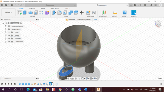
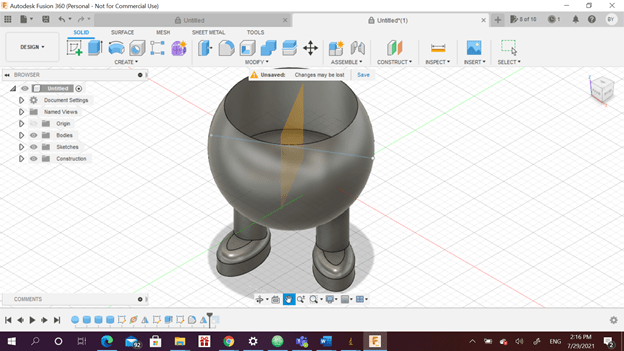
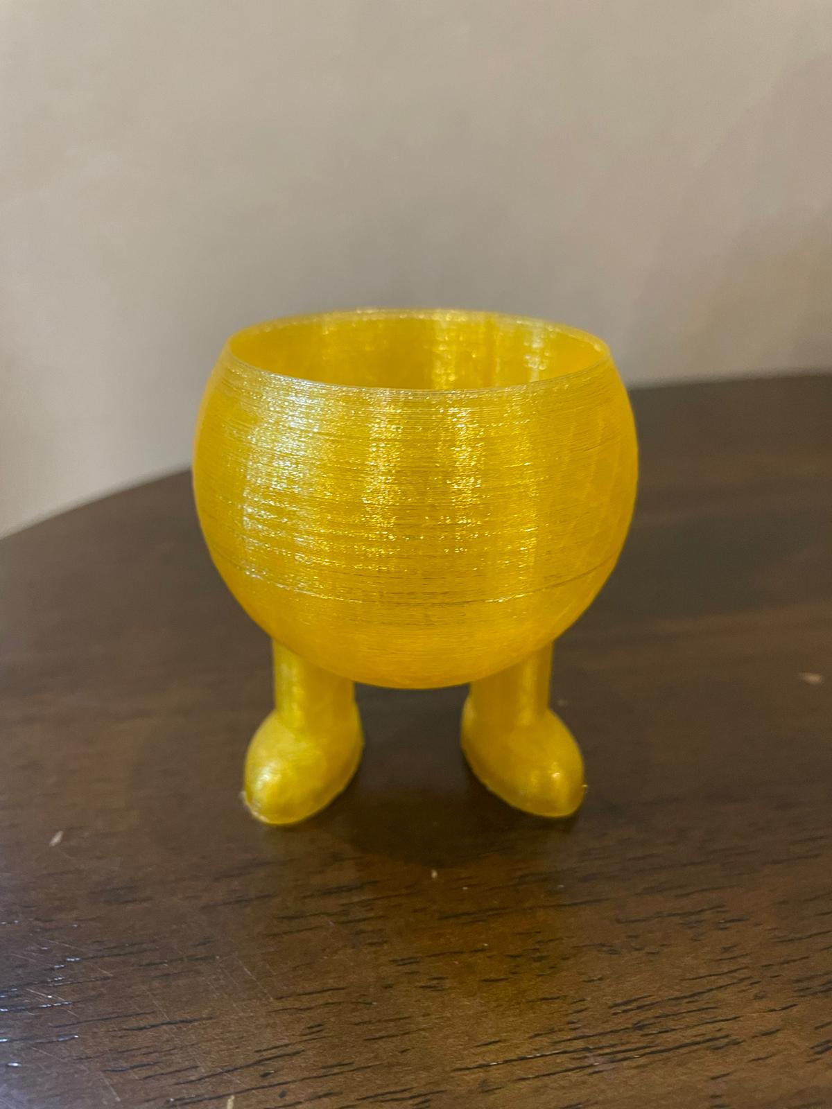
The first step is to design the object to be printed. It was designed using fusion 360. A sphere was constructed and then cut using a cylinder. Then the legs were located at the bottom. A line was sketched and plane along path was done to use the mirror later to create the other leg. The same procedure was done for the foot. A fillet was done for the feet to make it look smoother. The stl and fusion 360 files of the design will be attached down.
Printing Program
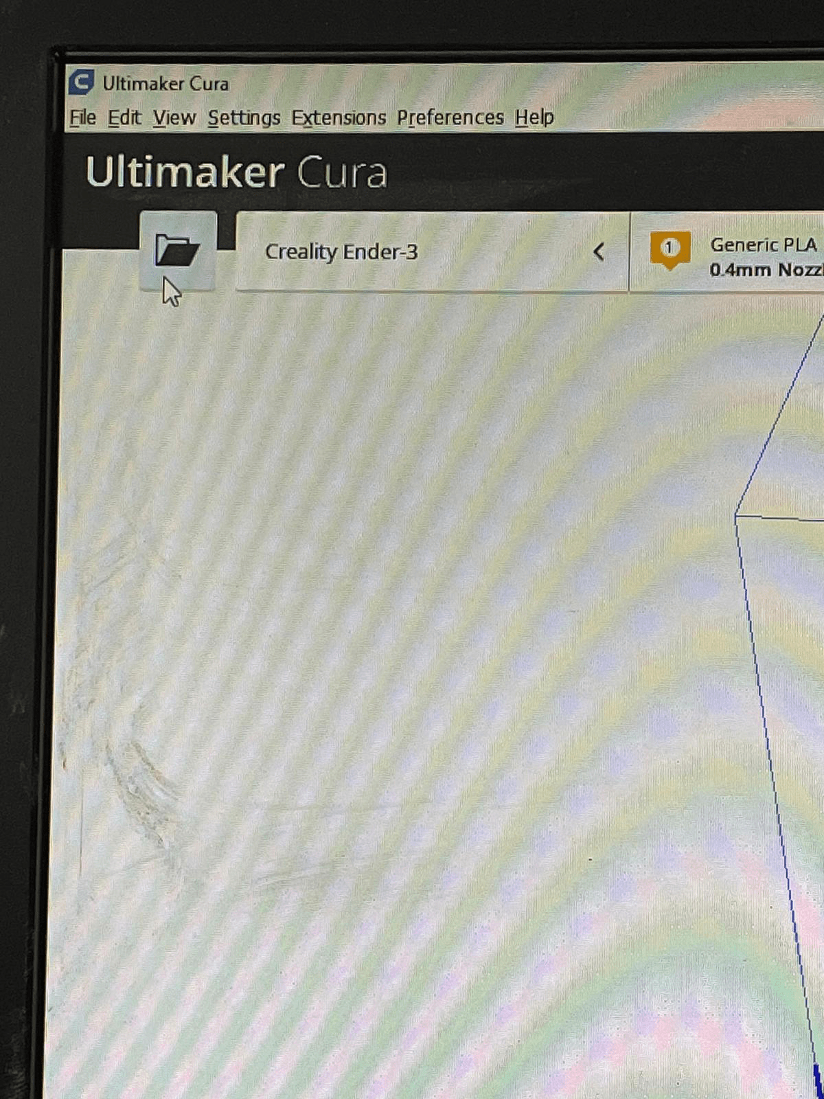
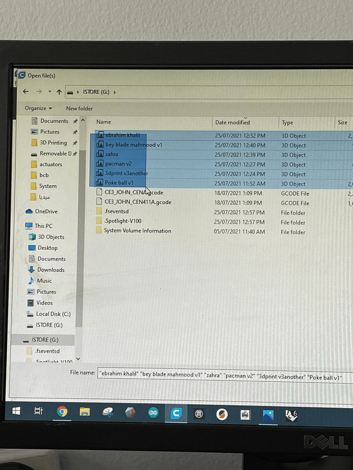
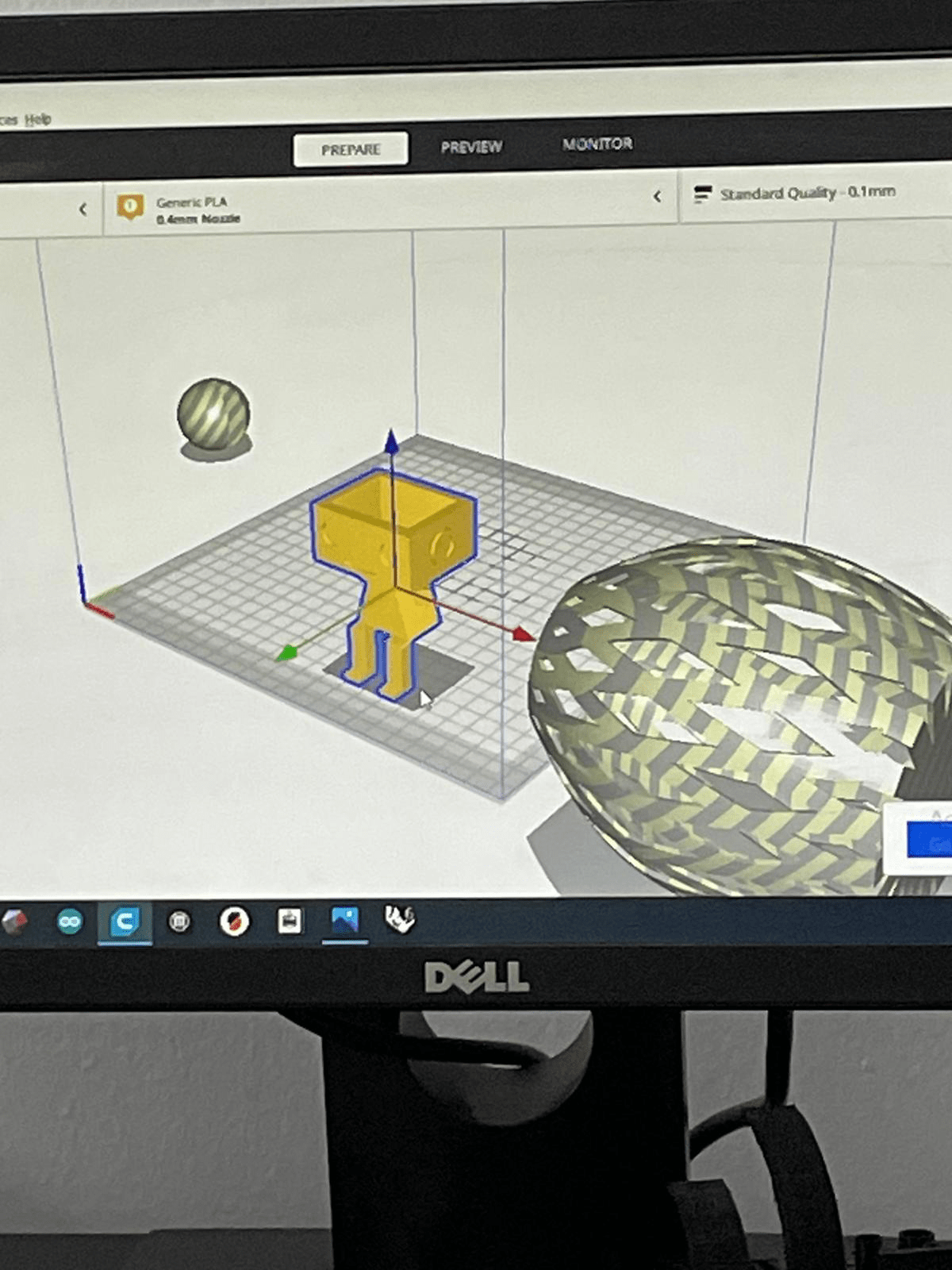
The used program is called Cura which was installed on Fablab computer. The file was opened as shown below and the desired files were selected.
Once the designs are imported they were arranged to be printed. The objects should be inside the box and not near the edges. When we put it near the edge it ignores the object and can’t print it.
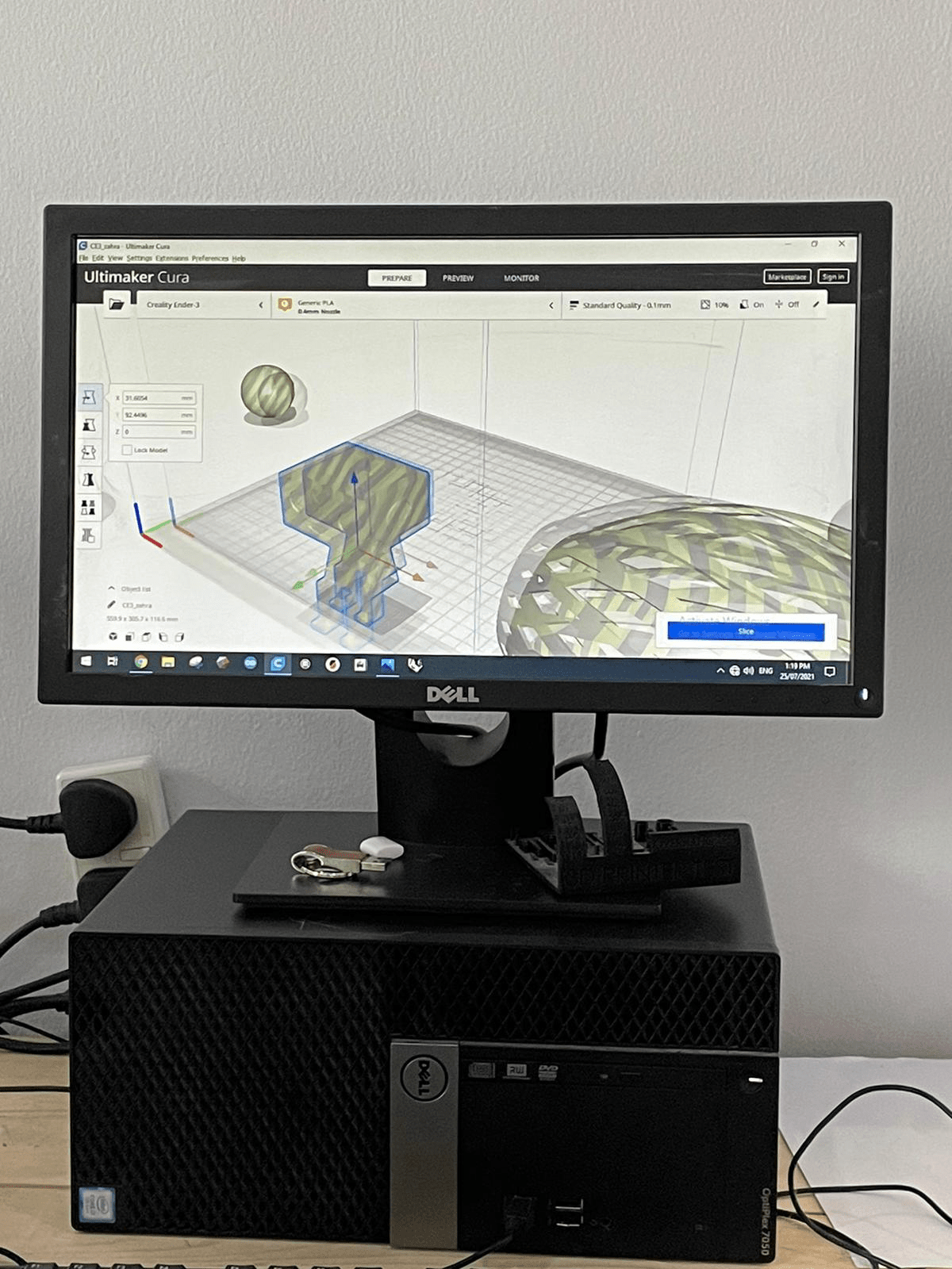
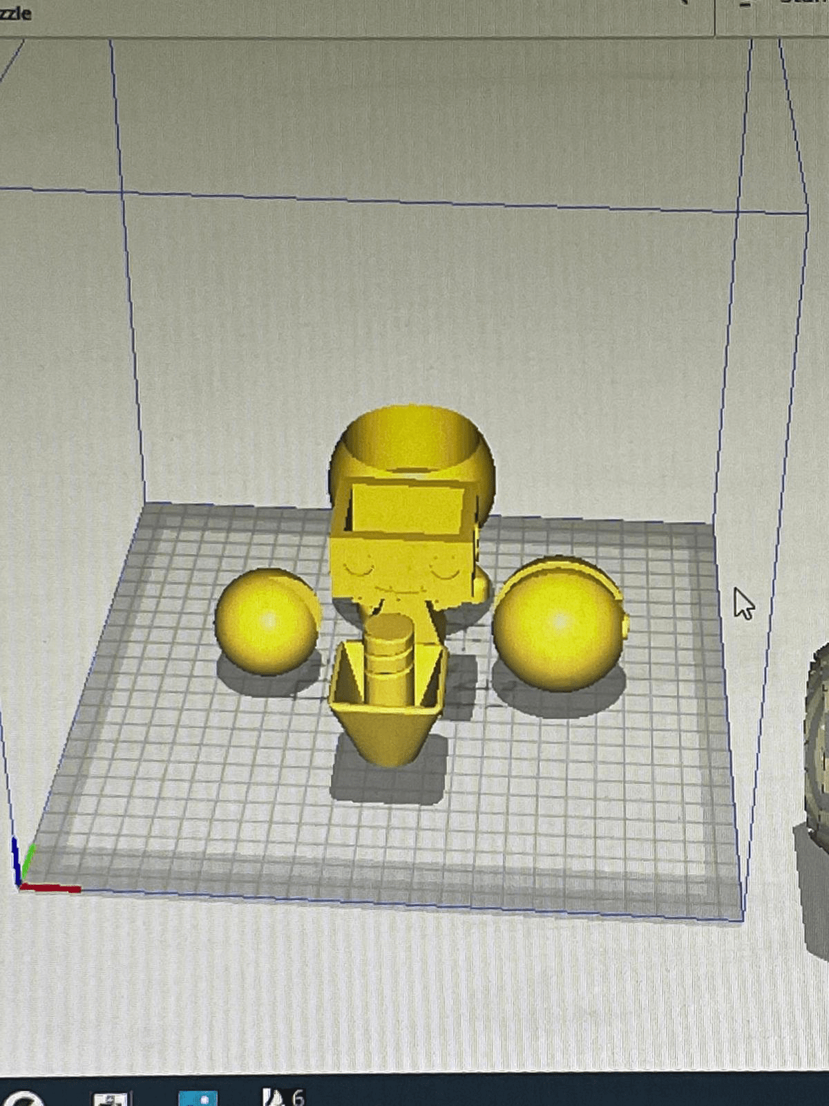
All objects are arranged inside the box.
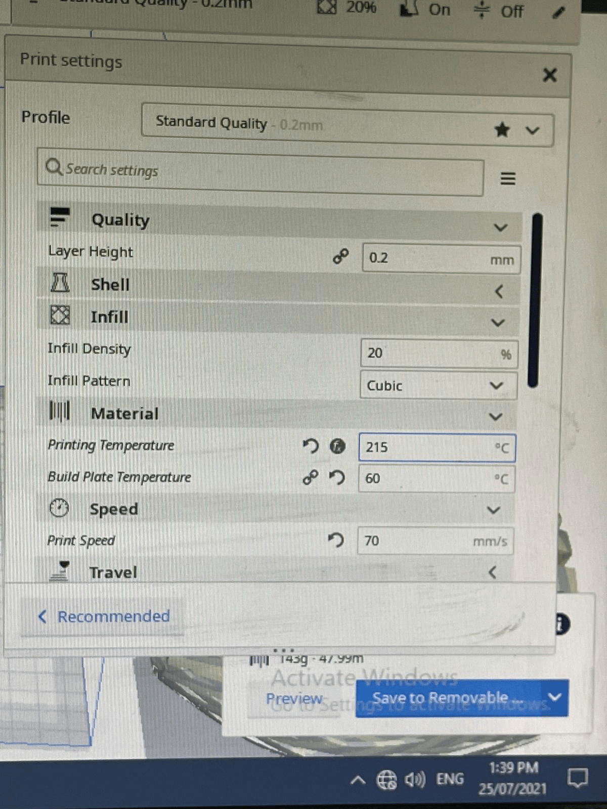
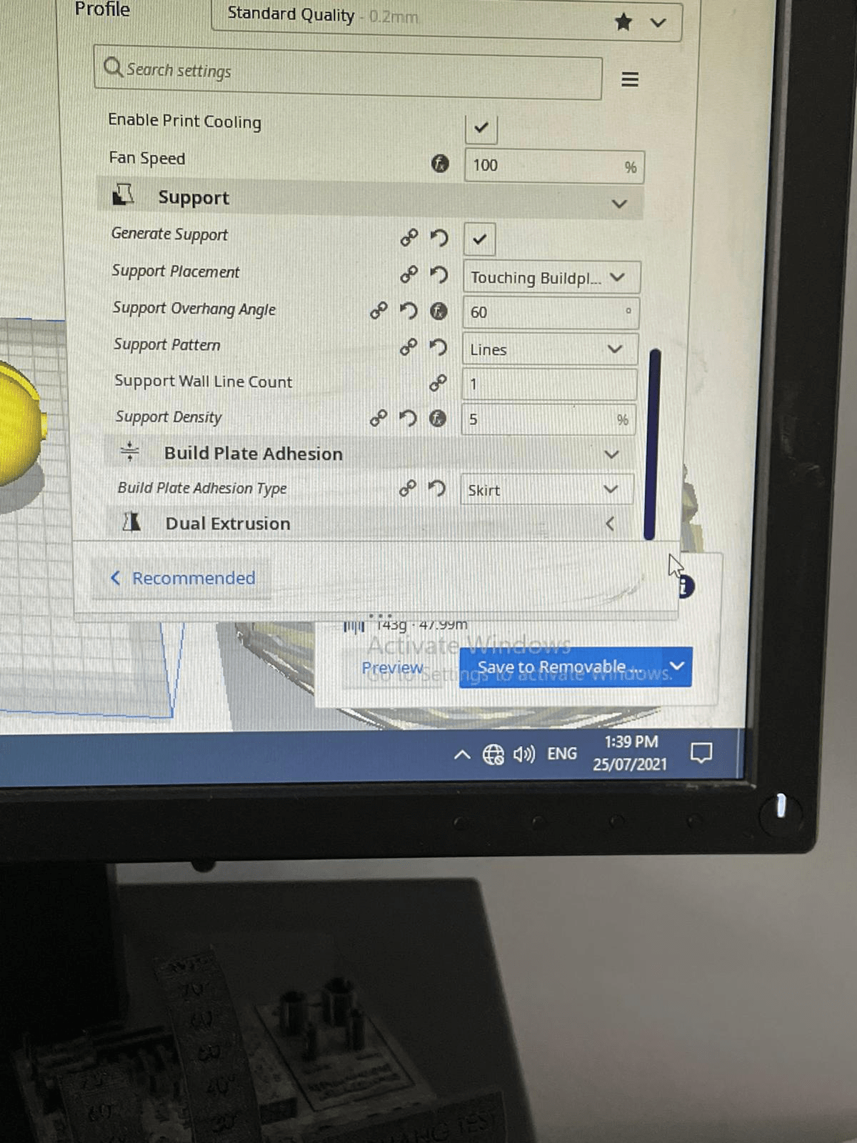
These are the settings that were assigned as following. The higher the layer height, the lower the quality and the higher the required time. The printing temperature and plate temperature were identified. The printing speed is inserted as 70 mm/s. The support overhang angle was adjusted to 60 degrees and the support density was put as 5%. The build plate adhesion type was chosen to be as skirt.
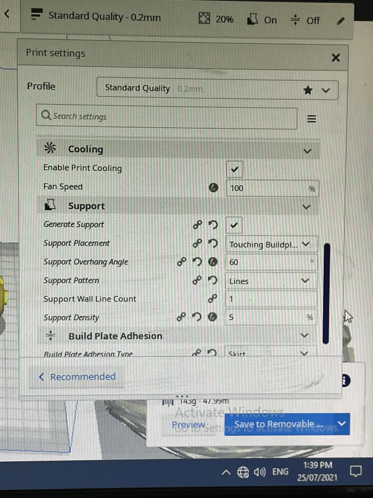
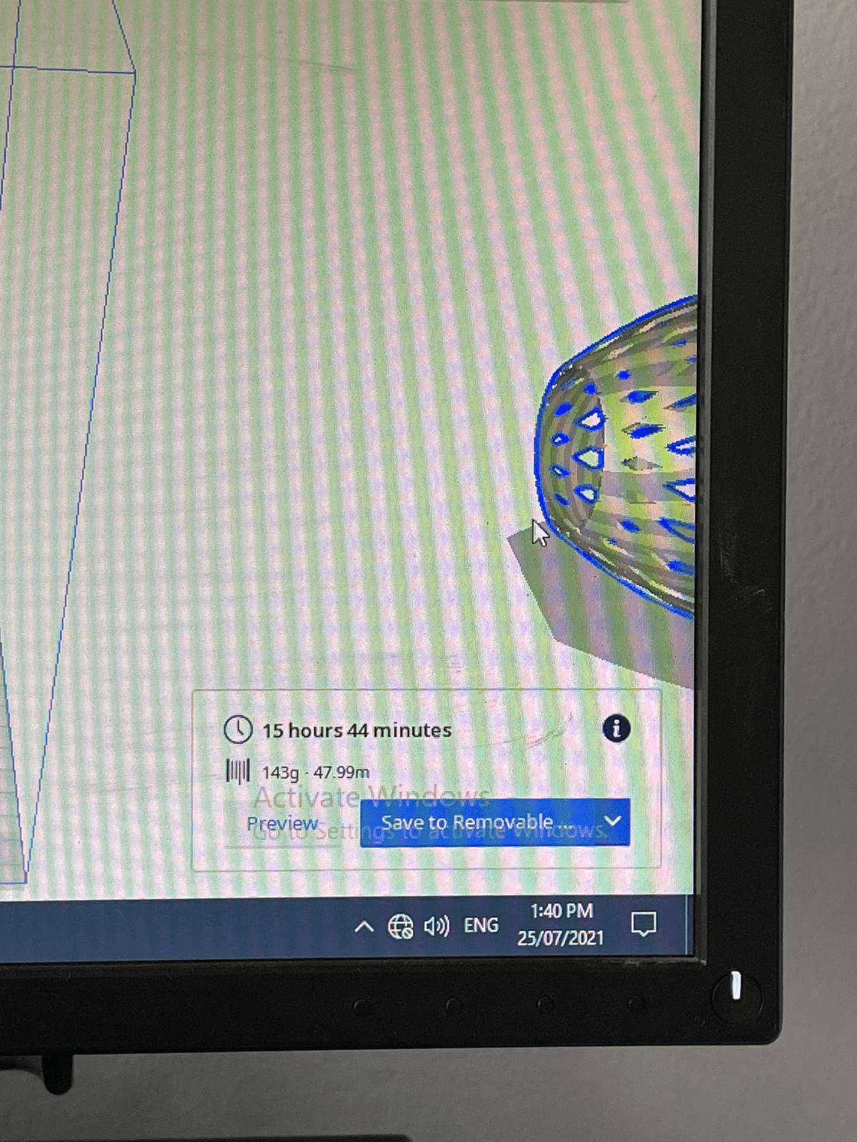
This is how the objects look with the support in blue and skirting around the objects in blue too.

The required time was calculated using the software.
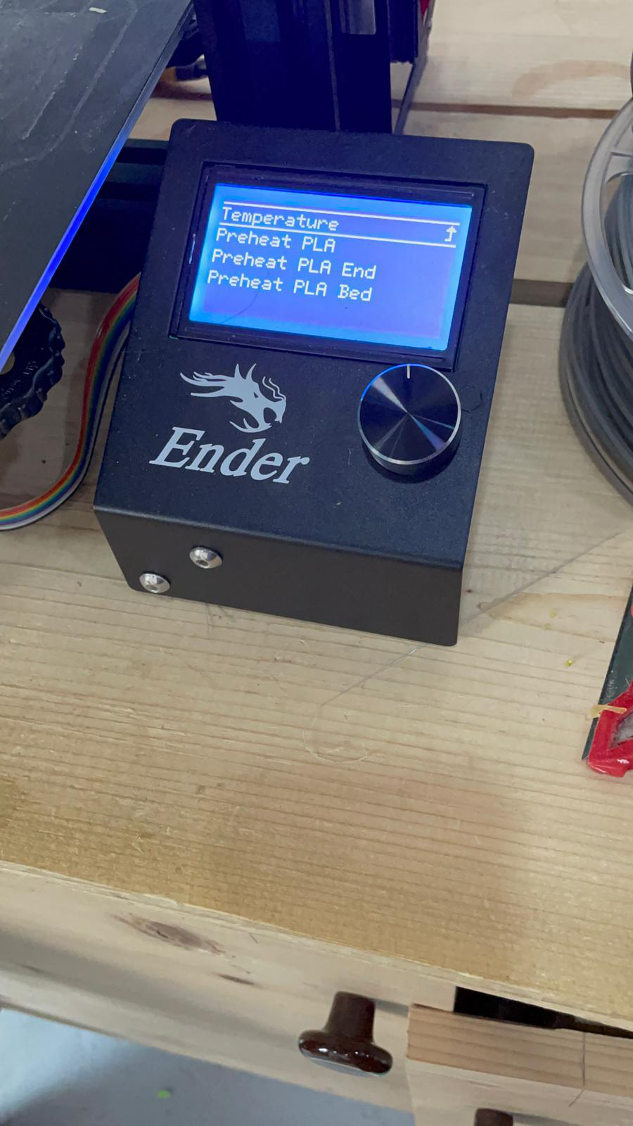
Both the bed and extruder should be heated by pressing on the following button.
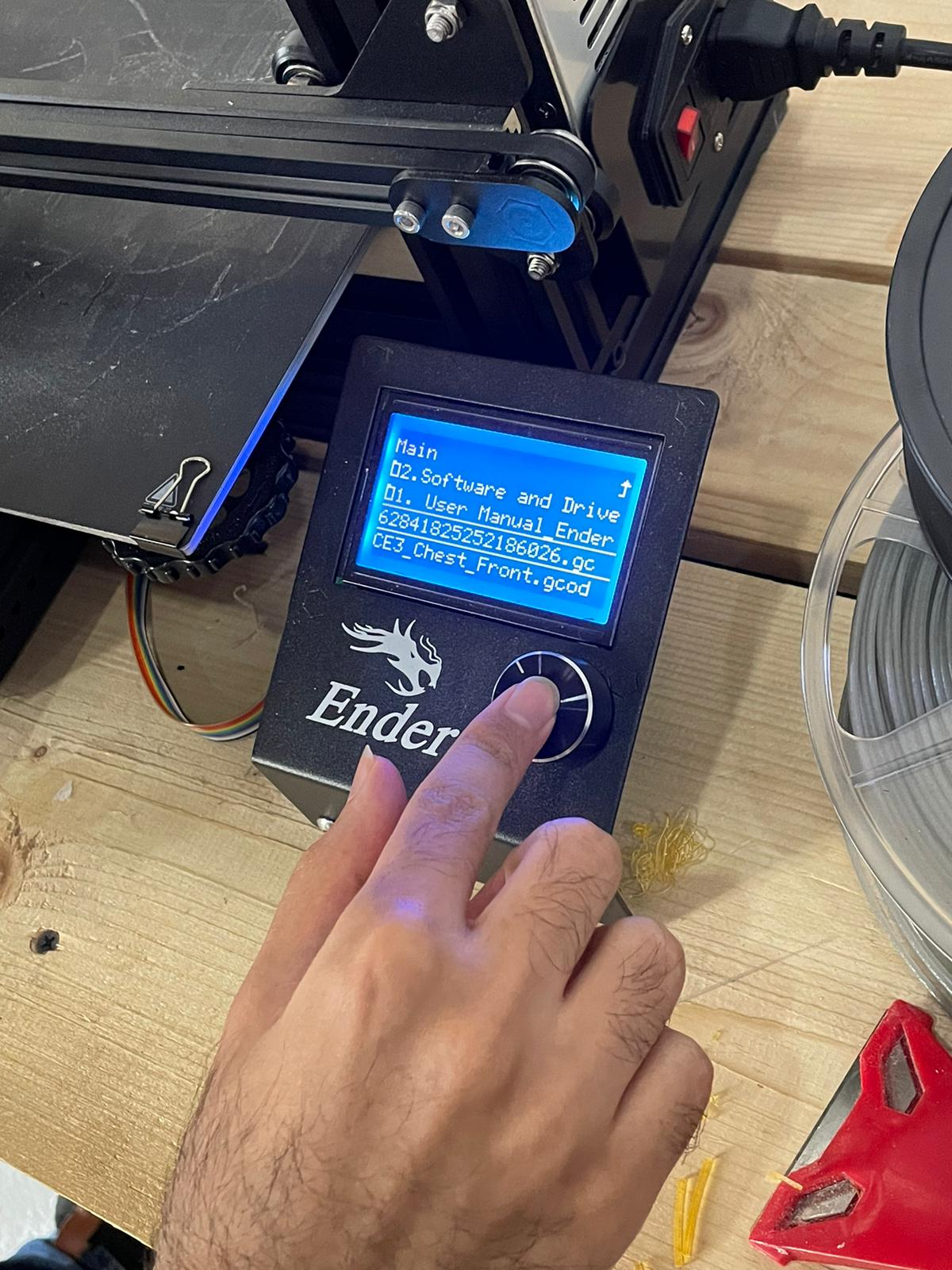
The desired file is chosen
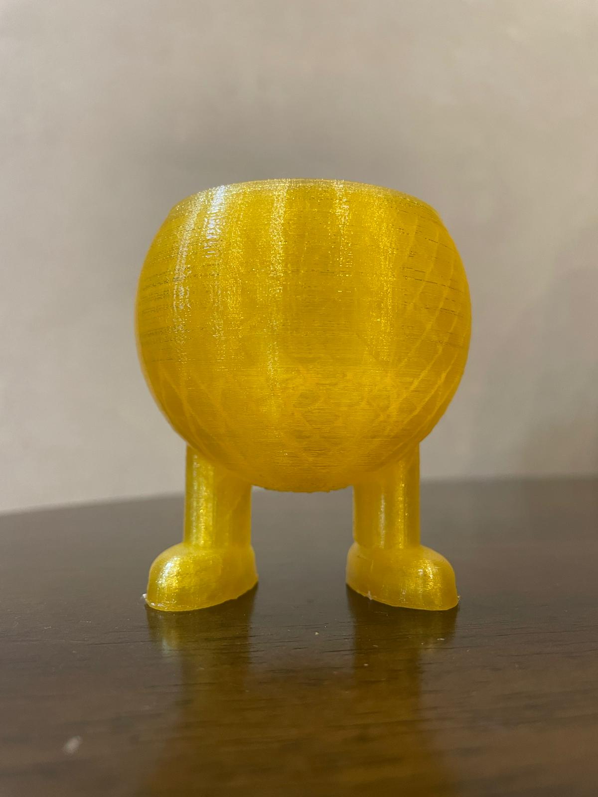
Once the printing was done, the support were removed. The result was good however butter quality could’ve been achieved to eliminate the lines that appears on the object.
3D scanning
3D scanning is a process were a real object/element from the real world is scanned and transformed into a digital sketch. Two programs were used to practice 3D scanning.
Qlone
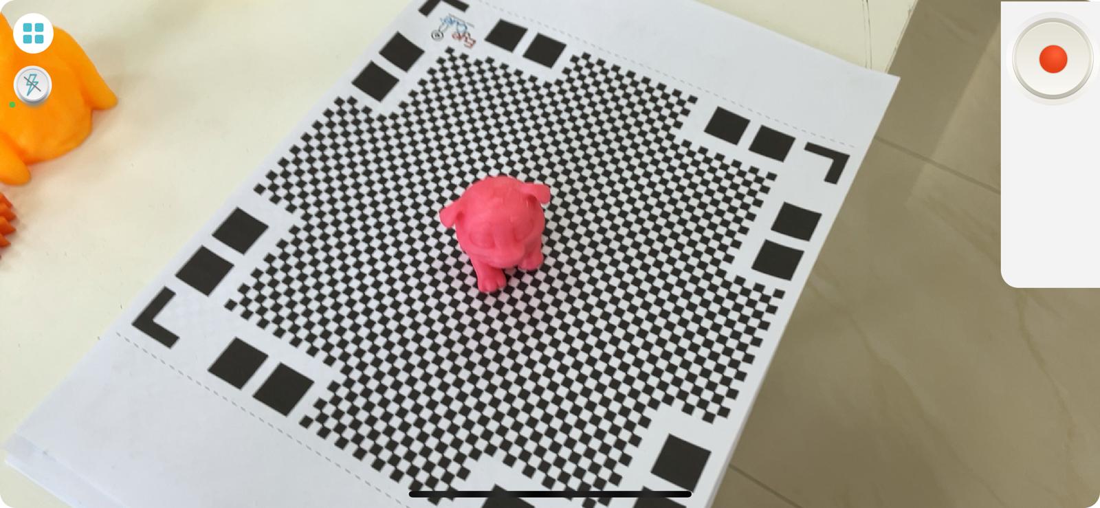
A program called Qlone was utilized to scan an object. It was downloaded on a smart phone where the phone’s camera is used to scan the object. A special mandatory Qlone mat was put under the object to be scanned.
This is the application logo

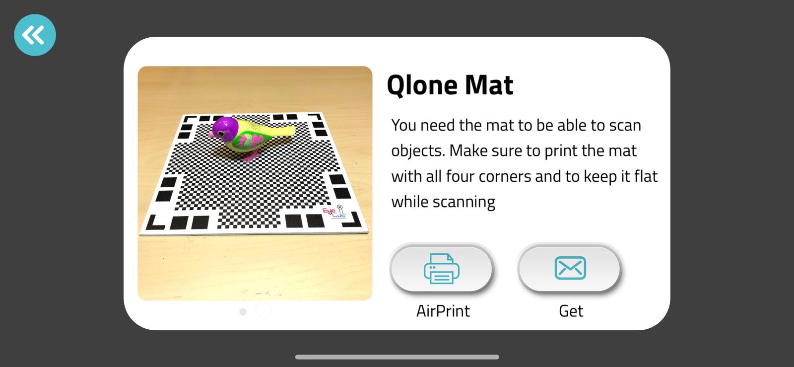
The mat was already printed by fablab team. However if you need to get the mat, the following steps should be pursued to get it.
1.Get Mat
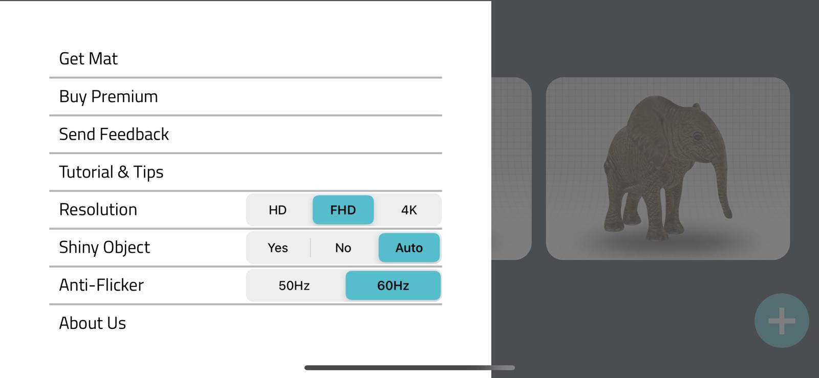
2.Get or AirPrint
Once the program is opened and the mat is placed under the object it should look like this in your camera. The red button should be pressed.
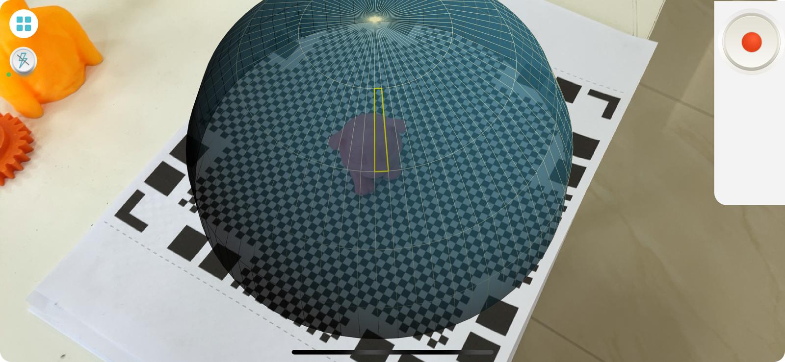
A dome appears and the slices can be eliminated by moving either the paper or the camera.
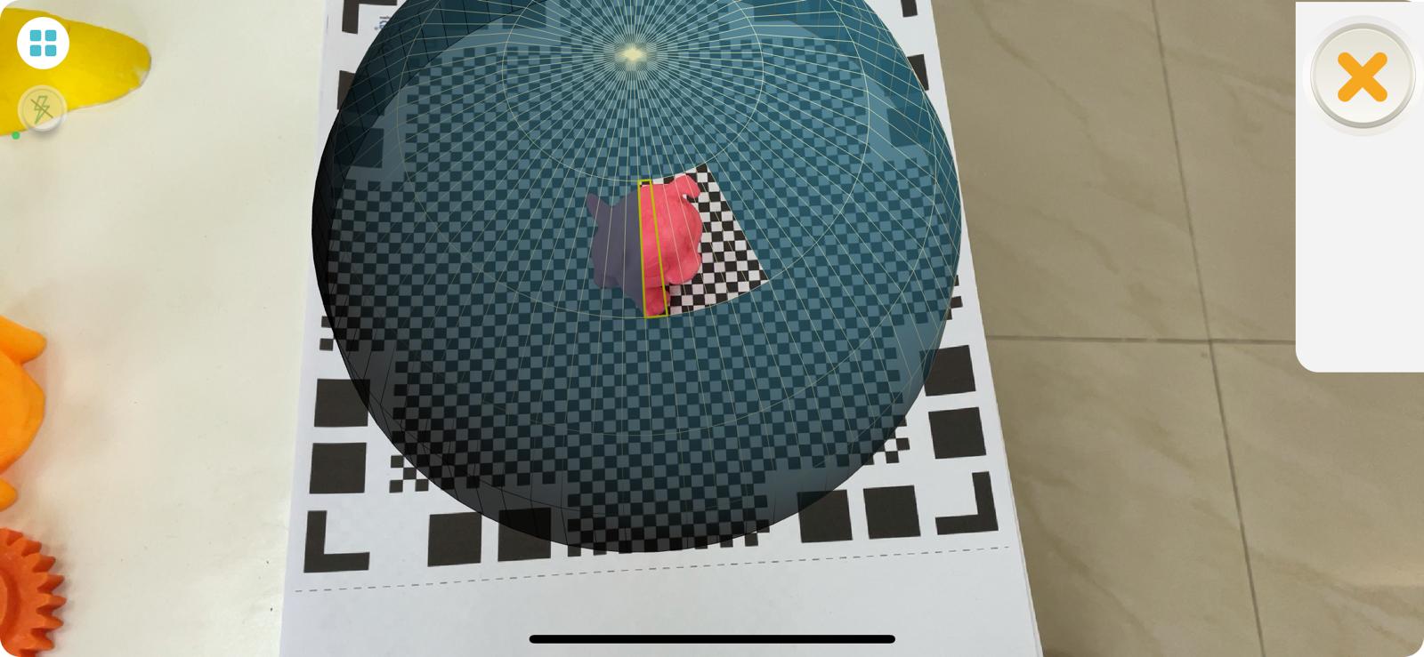
Once the dome is totally eliminated, the following 3D digital design is generated.
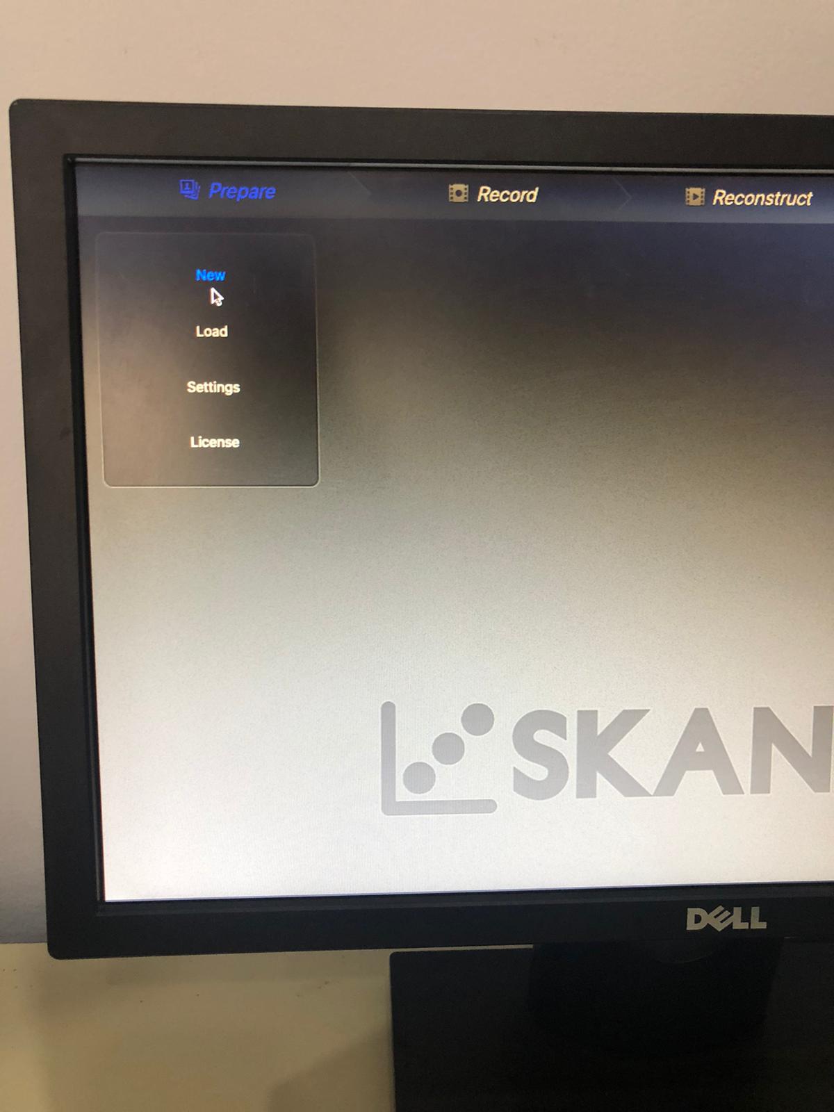
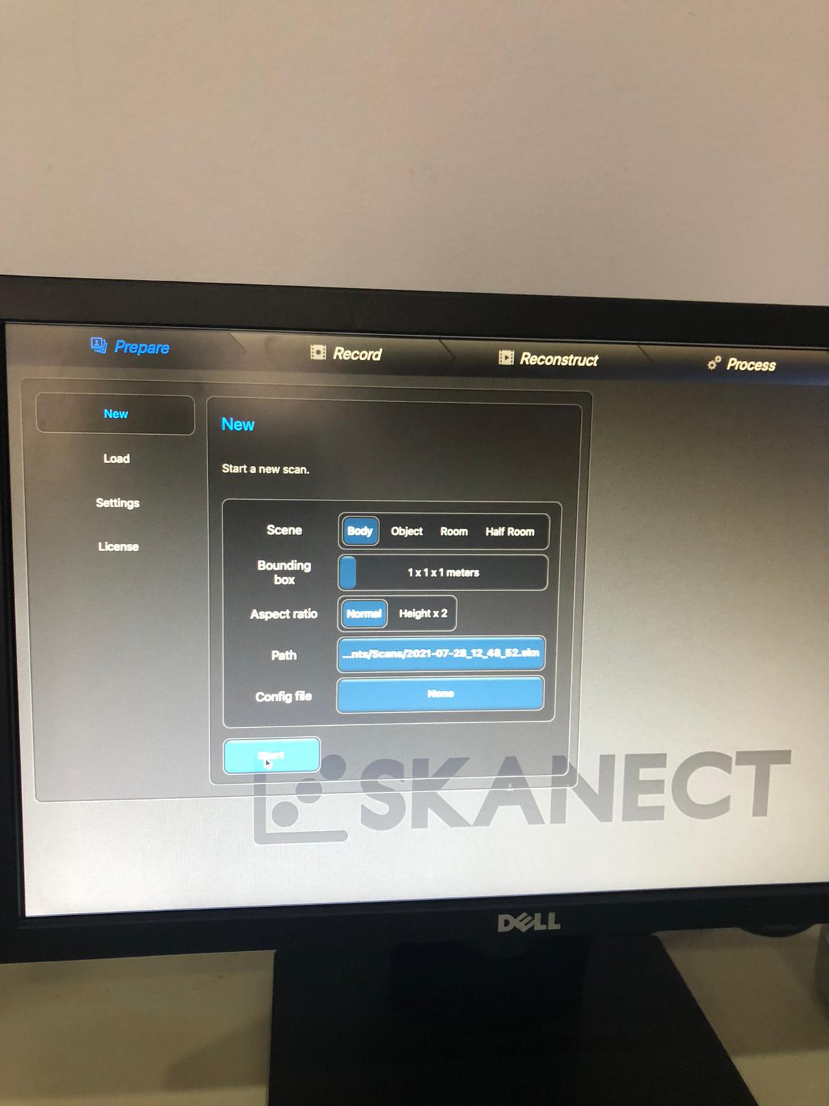
Skanet
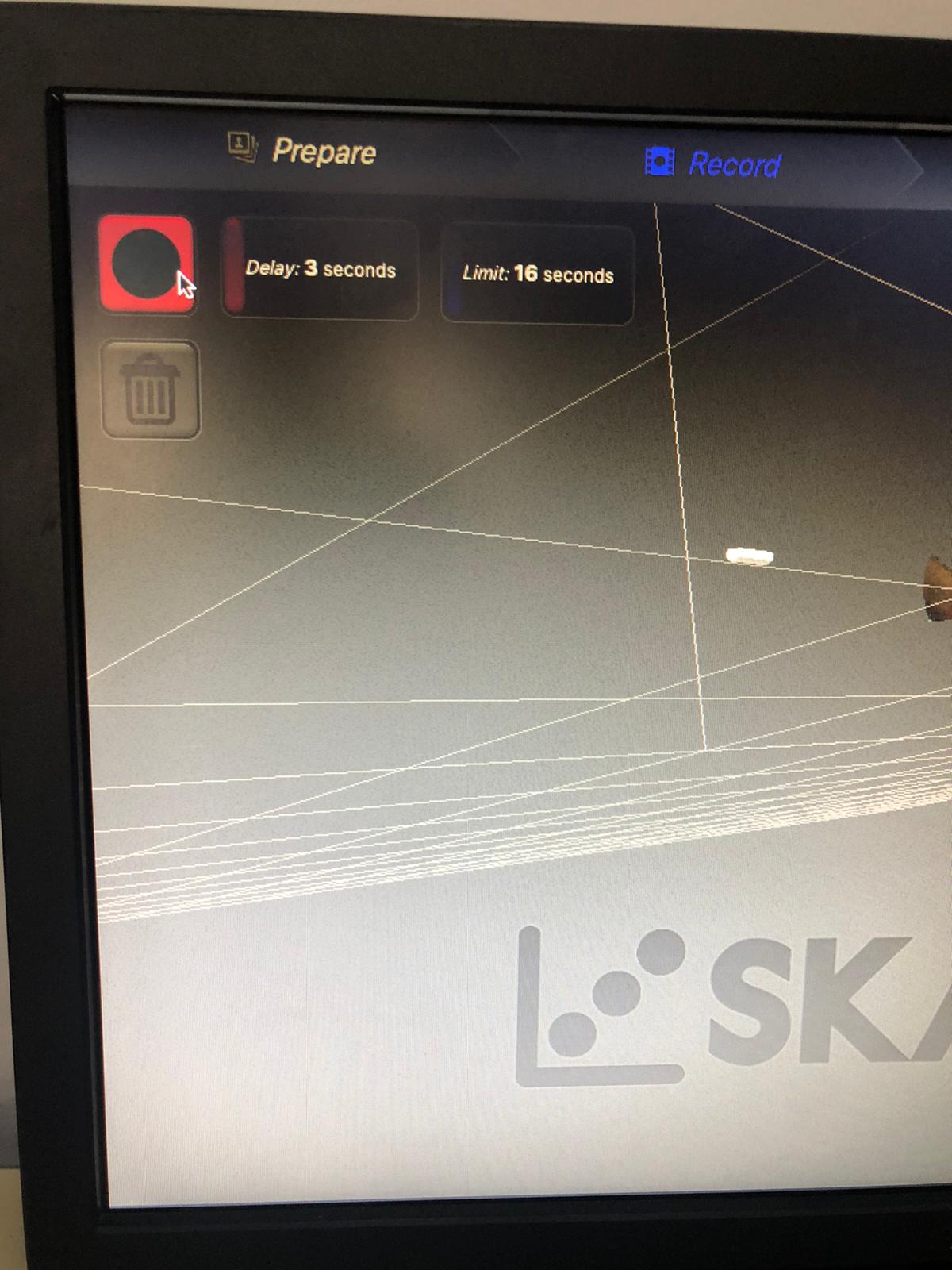
First, I started a new sketch, adjusted the limit time and started recording by clicking on the red square with black circle.
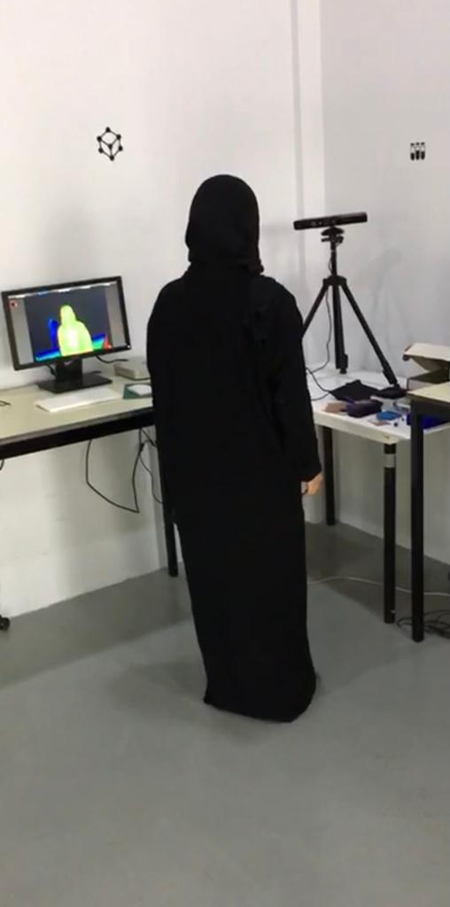
This is a picture of me while doing the process.
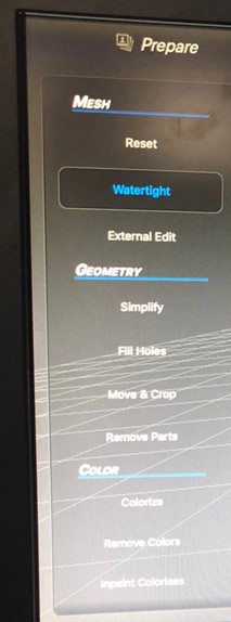
Once the sketch is taken I clicked fill holes to fill the gap that appears on the head and in bottom. Then click remove parts to remove any excess parts.
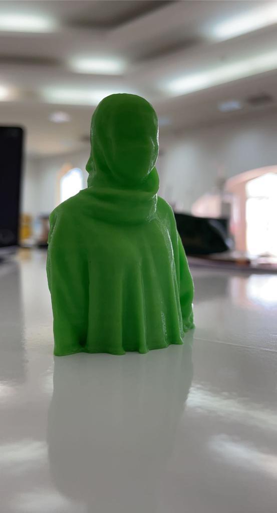
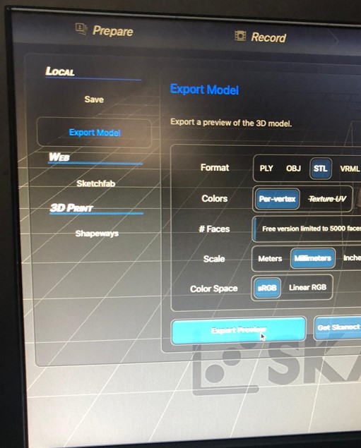
The design is then exported as following.
Finally, the stl file was transferred to the computer connected to the 3D printer and printed there. This is the final result.