10. Input/output devices
This week I worked on input and output devices which were connected to Arduino nano and programed using Arduino IDE software.
Input
Photoresistor
First, a photoresistor module was examined. The type provided by fablab was Arduino KY-018 Photoresistor module. A photoresistor is used to quantify the light intensity. Moreover, the module contains a photoresistor and 10 kΩ in line resistor. In the absence of light, the photoresistor’s resistance increases, and vice versa. The analog output determines light intensity. The device operating voltage is between 3.3 to 5V. To connect the photoresistor to the Arduino, the connect the signal (s), middle and ground pin (-) to pin A2, +5V and GRN pin located in the Arduino, respectively. The following picture illustrates the photoresistor connection to UNO Arduino.

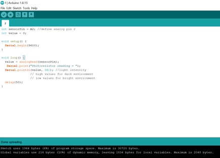
The following code was introduced to the microcontroller using Arduino IDE where the value read by the photoresistor appears. The brighter the intensity of the light, the lower the obtained value which agrees with what mentioned before about the relationship of resistance with light.
int sensorPin = A2; //define analog pin 2
int value = 0;

void setup() {
  Serial.begin(9600);
}

void loop() {
  value = analogRead(sensorPin);
   Serial.print("Photoresistor reading = ");
  Serial.println(value, DEC); //light intensity
                // high values for dark environment
                // low values for bright environment
  delay(50);
}
This is how the code looks in the software.
A modification was added to the code to open the Arduino nano light and write good night in the absence of bright light.
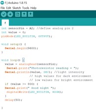
Whenever the reading is higher than 800 good night statement appears.
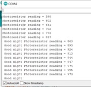
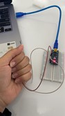
The photoresistor in ambient room light
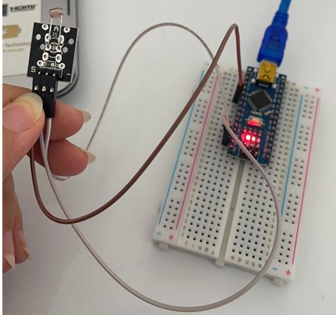
To create a dark environment the photoresistor is covered inside my hand.
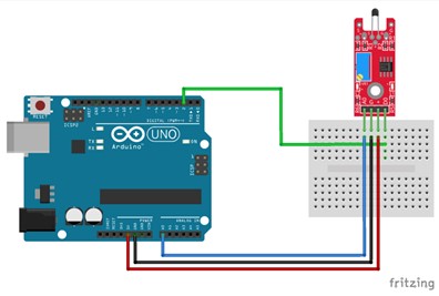
Temperature
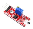
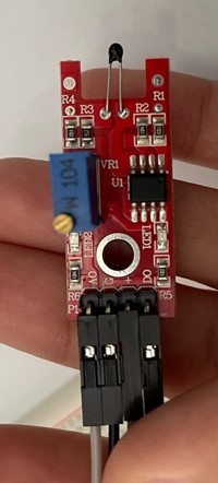
Digital Temperature Sensor KY-028 for Arduino is used to analyze and experience input devices. It measures temperature changes. The temperature sensor consists of thermistor resistance, digital and analog outputs and a potentiometer. The thermistor resistance measures the temperature while the digital input and analog input returns a numerical value depending on the exposure temperature and potentiometer position. The digital pin in the module which is referred to as (DO) is connected to a digital pin in the Arduino. Similarly, the analog pin (AO) and ground pin (G) are connected in the same way. The positive pin is connected to +5v pin in the Arduino. The following pictures illustrates the connection of the Arduino and the module.
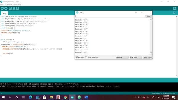
The following code was used to control the temperature sensor. The LED light opens when the sensor is connected to the Arduino. It prints the obtained temperature value.
int led = 13; // define the LED pin
int digitalPin = 2; // KY-028 digital interface
int analogPin = 2; // KY-028 analog interface
int digitalVal; // digital readings
int analogVal; //analog readings
void setup() {
pinMode(LED_BUILTIN, OUTPUT);
Serial.begin(9600);
}

void loop() {
  // Repeat the process:
analogVal = analogRead(analogPin);
 Serial.print("Reading =");
  Serial.println(analogVal); // print analog value to serial

  delay(50);
}
To mentor the module reading serial monitor was opened.
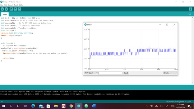
The obtained measurements were plotted in a curve.
This curve resulted when the sensor was left alone in ambient temperature.
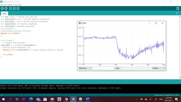
This curve illustrates the reading of the sensor when I left the sensor free than put my hand around the sensor then remove it later. Of course, the room temperature is lower than our body. This means that a high voltage value is obtained when the temperature is low and vice versa. The resistance increases when the temperature decreases. Thus, the resistance has an inversely proportional relationship to the temperature and a proportional relationship to the voltage.
Output
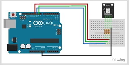
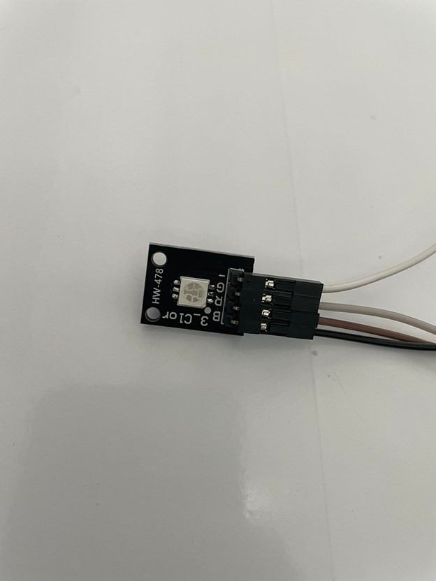
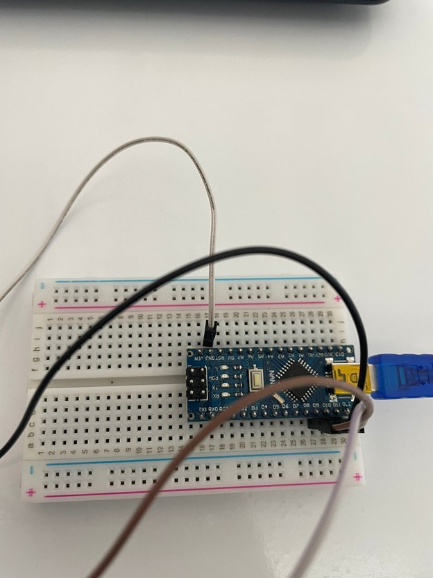
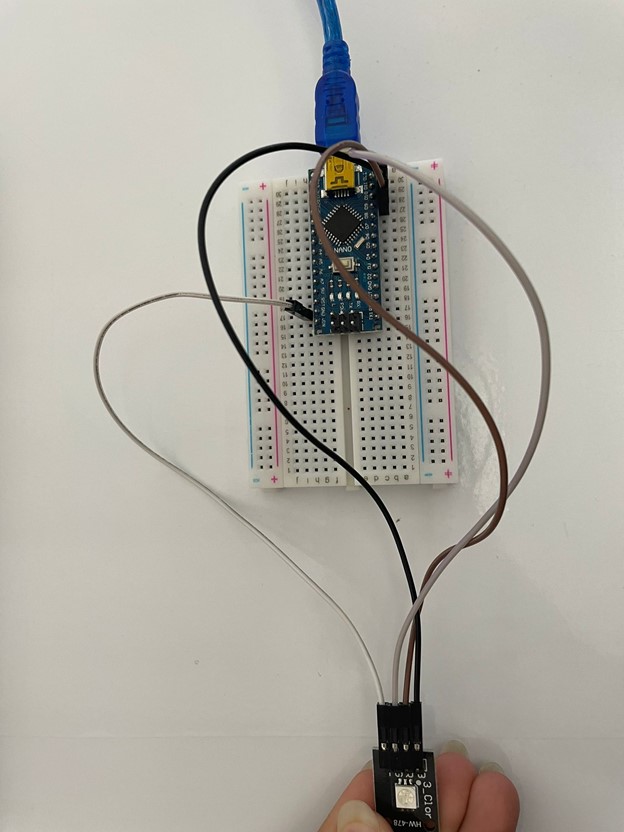
Arduino KY-009 3-color LED SMD module was used to study output. The output module can emit a range of colors by mixing red, green and blue light. The amount of light is adjusted using the code. The module consists of a 5050 SMD LED, use with limiting resistors to avoid any possible burnout. The module has a maximum operating voltage of 5V. The following figure represent the connection for the output module to the Arduino UNO. It can be similarly attached to Arduino nano. The ground pin, R, G, B should be connected to the ground pin, 9, 11 and 10 in the Arduino nano, respectively.
The following code was used to create a mixture of all colors. The fraction of each color depends on the value given by the code.
int redpin = 9; // pin for the red LED
int bluepin =10; // pin for the  blue LED
int greenpin = 11;// pin for the green LED

int val;

void setup() {
  pinMode(redpin, OUTPUT);
  pinMode(bluepin, OUTPUT);
  pinMode(greenpin, OUTPUT);
  Serial.begin(9600);
}

void loop()
{
  for(val = 255; val > 0; val--)
  {
    analogWrite(redpin, val);  //set PWM value for red
    analogWrite(greenpin, 255 - val); //set PWM value for green
    Serial.println(val); //print current value
    delay(100);
  }
    for(val = 255; val > 150; val--)
  {
    analogWrite(bluepin, val); //set PWM value for blue
    Serial.println(val); //print current value
    delay(100);
  }
  }
A traffic light code was later developed to challenge myself. The code depends on the time period identified in the code for each color mixture of red, mixed green and red and finally pure green color. A suitable statement appears to indicate the meaning of each color in traffic language.
int redpin = 9; // pin for the red LED
int bluepin =10; // pin for the  blue LED
int greenpin = 11;// pin for the green LED
int val;

void setup() {
  pinMode(redpin, OUTPUT);
  pinMode(bluepin, OUTPUT);
  pinMode(greenpin, OUTPUT);
  Serial.begin(9600);
}

void loop()
{
     Serial.print("Stop "); //print current value
  for(val = 255; val > 150; val--){
    analogWrite(redpin, val);  //set PWM value for red
  delay(50);
  }

  Serial.print(" Be ready "); //print current value
   for(val = 200; val > 100; val--){
    analogWrite(redpin, 220);  //set PWM value for red
    analogWrite(greenpin, 30);  //set PWM value for red
     delay(50) ;
  }
  Serial.print(" Go"); //print current value
    for(val = 255; val > 150; val--){
    analogWrite(greenpin, val); //set PWM value for green
   delay(50);
  }
  delay(3000);
}
To see a video of the traffic light working click here
Input and Output Devices
Finally, input and output modules were utilized together. Furthermore, the code was written so that the input controls the output. The input device was the previously used photoresistor whereas the output device was the 3 colors light. The code simply tunes the light intensity of the LED light according to brightness of the environment. If the environment is bright and its morning, the LED will be brighter because it’s hard to see because of the sun light. In contrast, in the evening, normal light intensity is sufficient to recognize the color. When the light intensity if the traffic light is high because it is morning, the Arduino nano light turns on, and vice versa.
int sensorPin = A2; //define analog pin 2
int value = 0;

int redpin = 9; // pin for the red LED
int bluepin =10; // pin for the  blue LED
int greenpin = 11;// pin for the green LED
int val;

void setup() {
  pinMode(LED_BUILTIN, OUTPUT);
  pinMode(redpin, OUTPUT);
  pinMode(bluepin, OUTPUT);
  pinMode(greenpin, OUTPUT);
  Serial.begin(9600);
}

void loop()
{value = analogRead(sensorPin);
  if (value <= 800) { // It's morning
Serial.print(" High traffic light intensity ");
   digitalWrite(LED_BUILTIN, HIGH);

  Serial.print(" Go"); //print current value
    for(val = 255; val > 150; val--){
    analogWrite(greenpin, val); //set PWM value for green
   delay(50);
  }
  }
  if (value > 800)
  {
    Serial.print(" Low traffic light intensity ");
    digitalWrite(LED_BUILTIN, LOW);

  Serial.print(" Go"); //print current value
    for(val = 150; val > 50; val--){
    analogWrite(greenpin, val); //set PWM value for green
   delay(50);
  }
  }
  delay(3000);
}
To see the result of this code click here
Useful links
Morse code
// Wait as a morse code
int dot = 500;
int dash = 1000;

void setup() {
  // put your setup code here, to run once:
 pinMode(LED_BUILTIN, OUTPUT);

}

void loop() {
  // put your main code here, to run repeatedly:
morsefunction(dot);
morsefunction(dash);
morsefunction(dot);
morsefunction(dot);
morsefunction(dot);
delay (3000);
}
void morsefunction(int dot0Rdash) {
  digitalWrite(LED_BUILTIN, HIGH);
  delay(dot0Rdash);
digitalWrite(LED_BUILTIN, LOW);
delay(500);