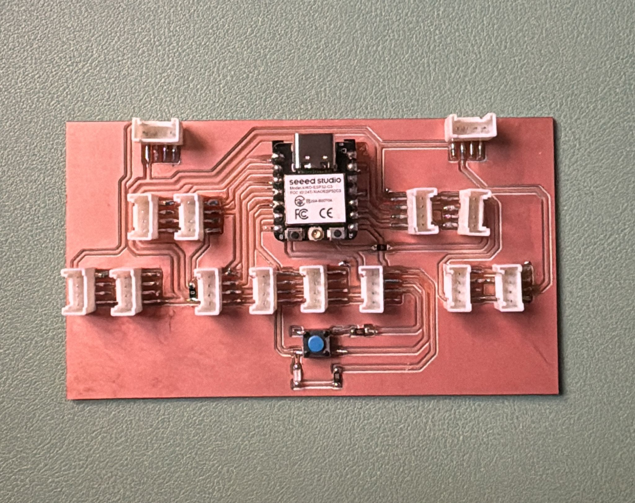
For this week’s production assignment, I milled the circuit board I designed earlier during Electronics Design week. The board is built around the XIAO ESP32C3 microcontroller and includes multiple SMD Grove connectors, which makes it easy to plug in different input and output devices using Grove cables.
I also added a pushbutton and a built-in LED directly on the PCB. This makes quick code testing a lot easier without needing to wire up anything extra. The board was specifically designed to support the kind of input/output setup I’ll need for my final project — so producing it this week was an important step toward bringing the full idea to life.
To get started with milling, I used the circuit I fully designed in KiCad during Electronics Design week. All the preparation steps—like schematic and footprint linking—were already covered back then, so now I just needed to get everything ready for production.
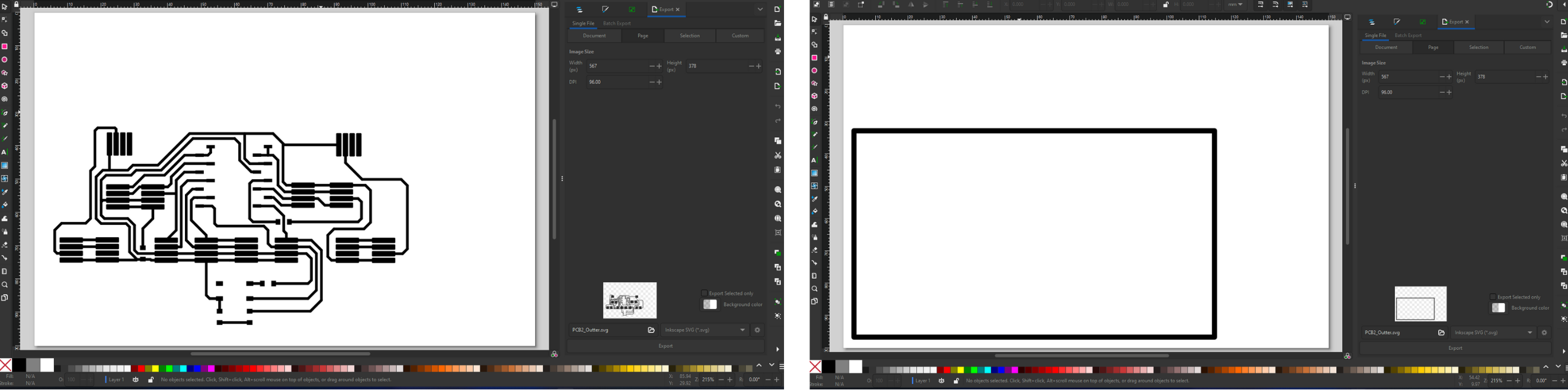
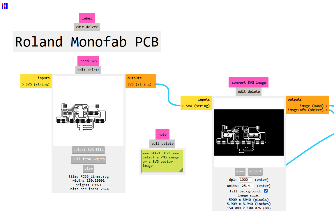
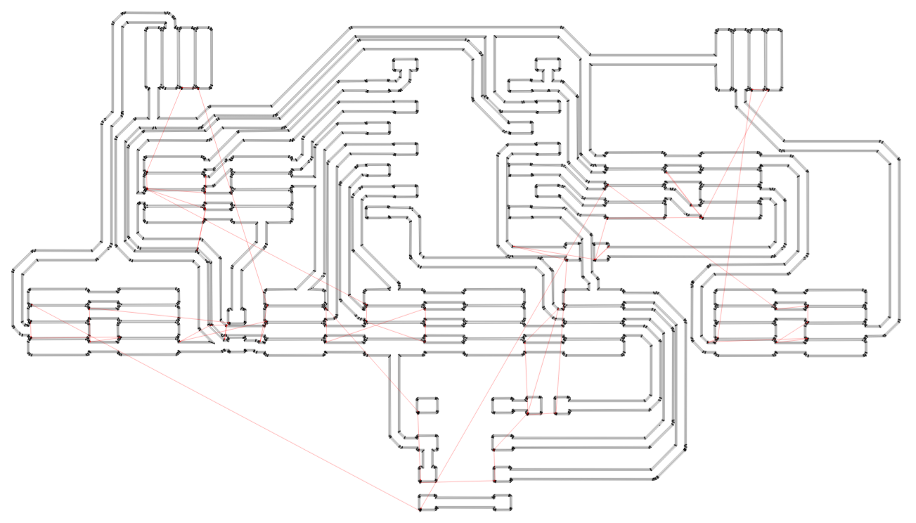
I exported the design as SVG files, since SVGs are easy to handle in multiple software tools. Specifically, I created two separate SVG files: one for the circuit trace paths, and another for the board outline cut. I used Inkscape to cleanly separate the layers and export each part individually.
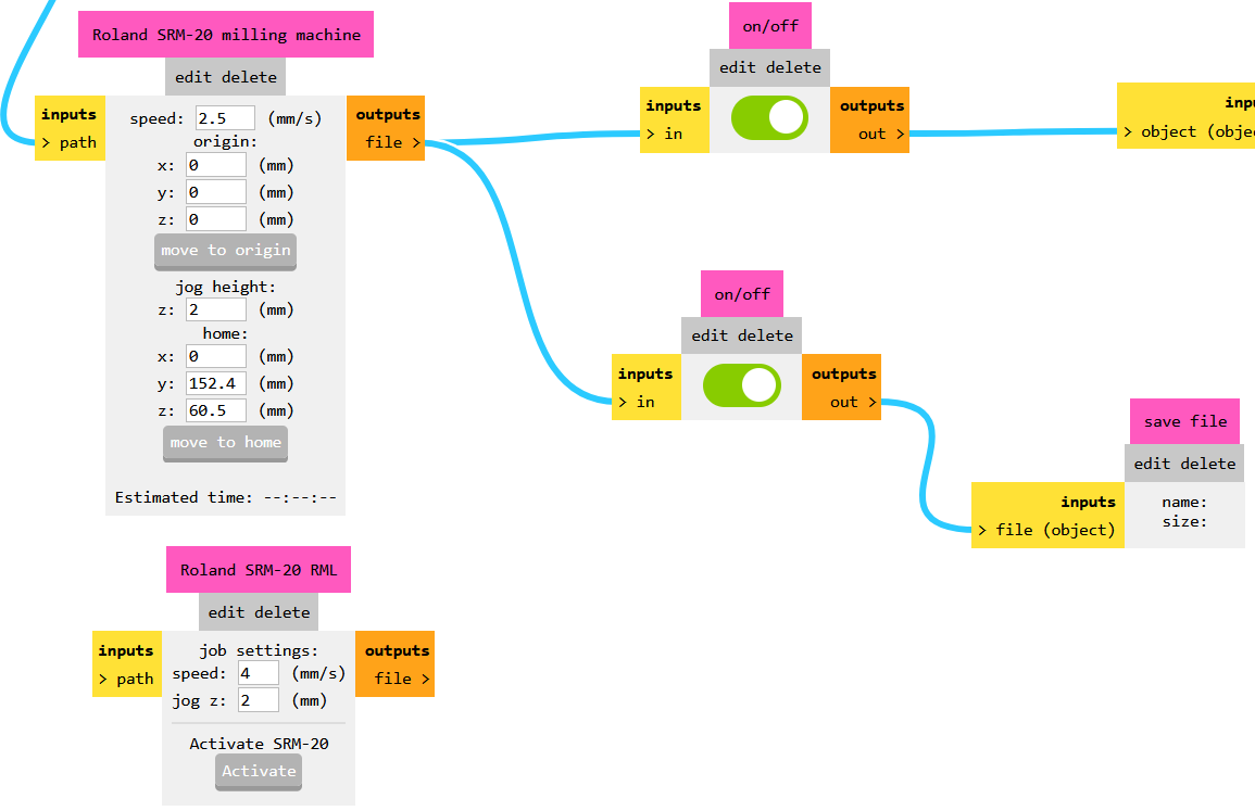
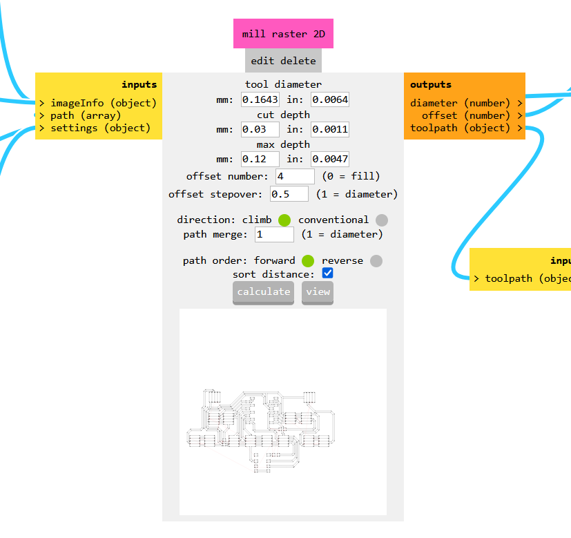
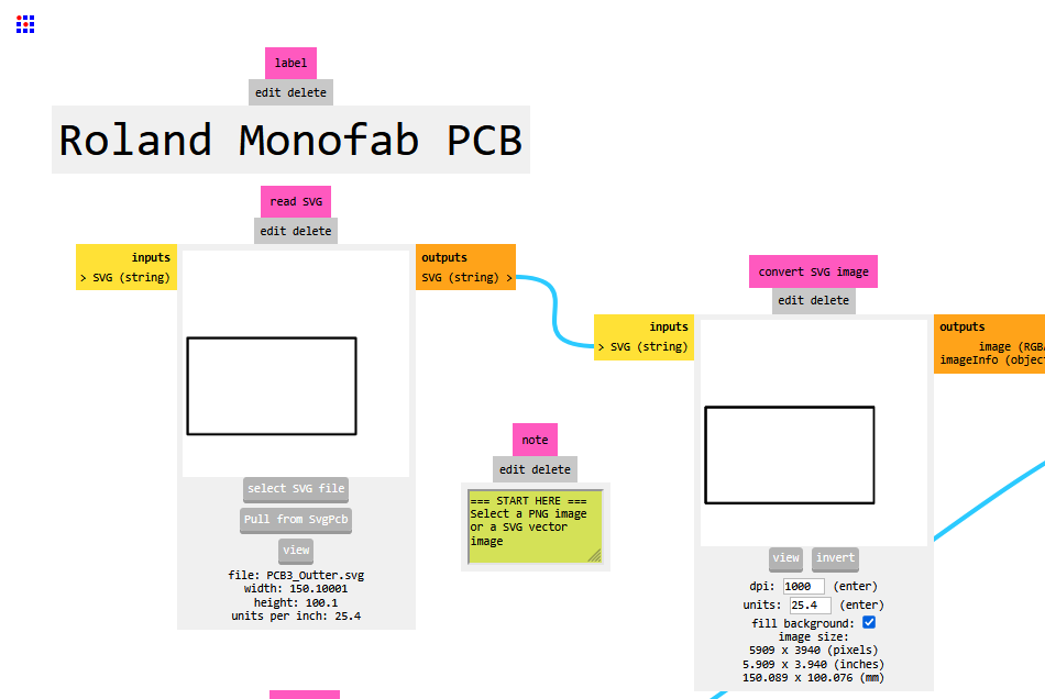
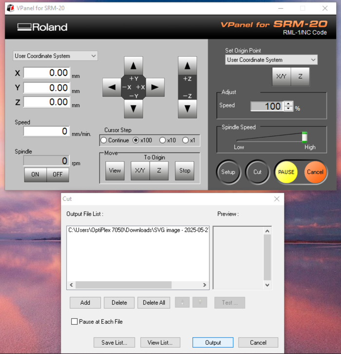
I used modsproject.org to generate the actual milling paths for the Roland SRM-20 machine in our lab. Here’s how it went:
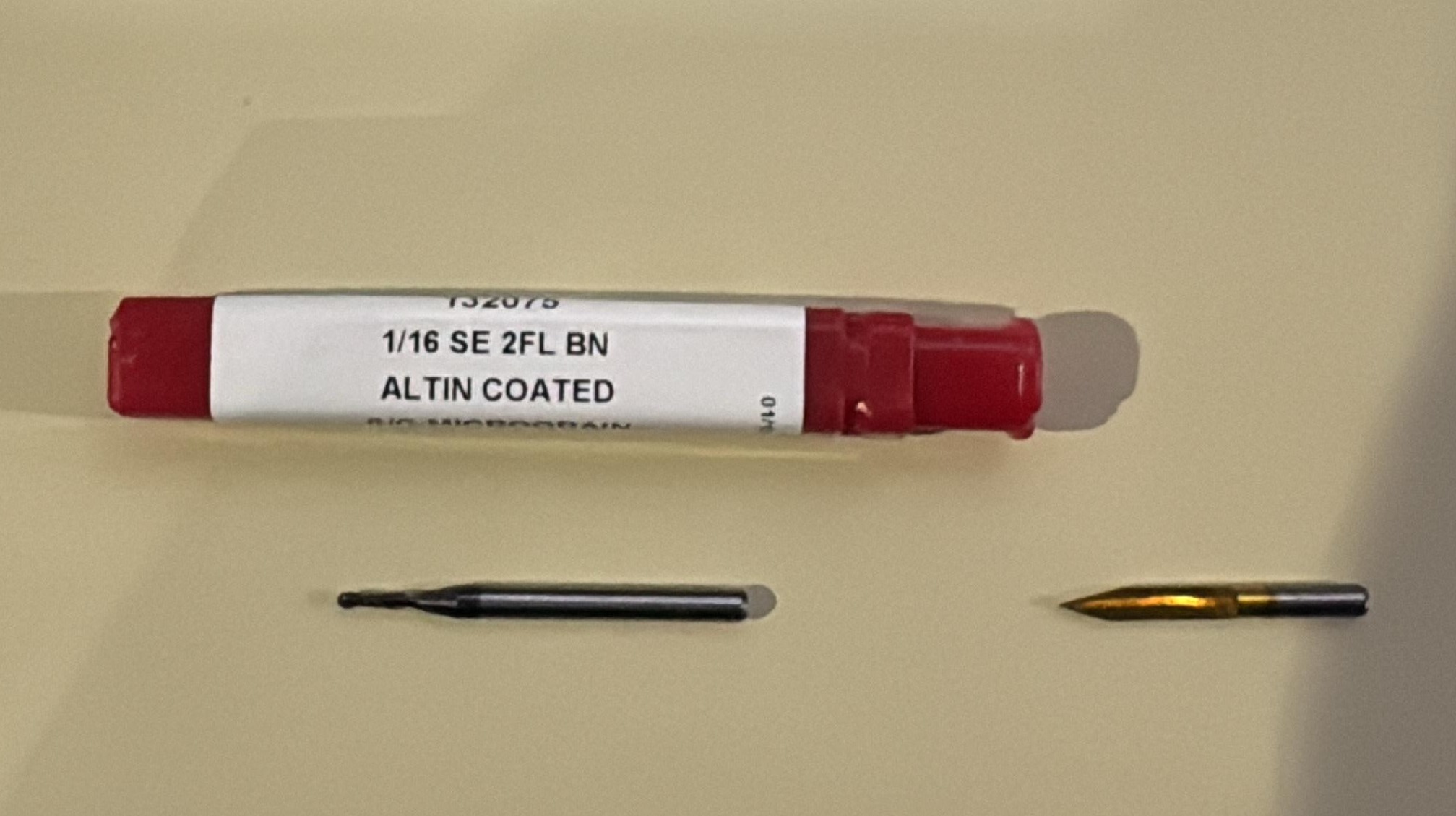
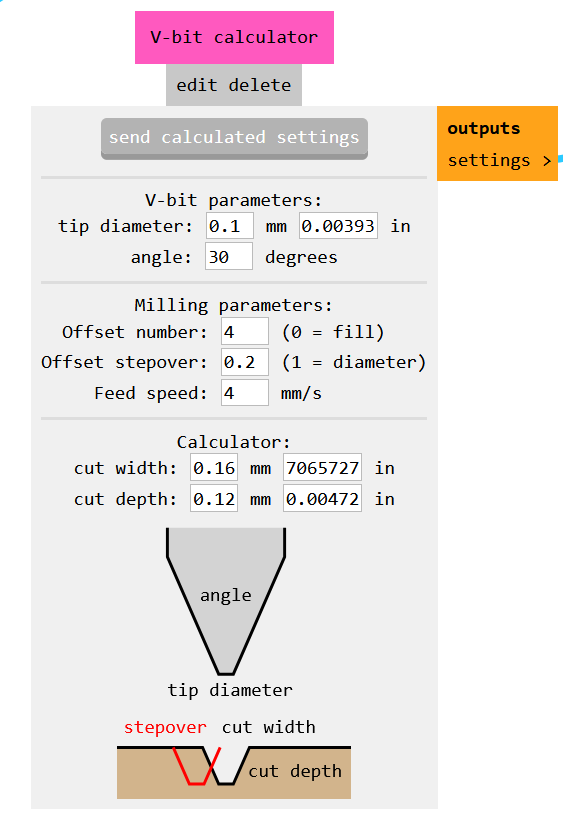
It’s important to know what bits are available in your lab before generating the toolpaths. If you're unsure, ask your instructor or search online for recommended bit sizes for PCB milling.
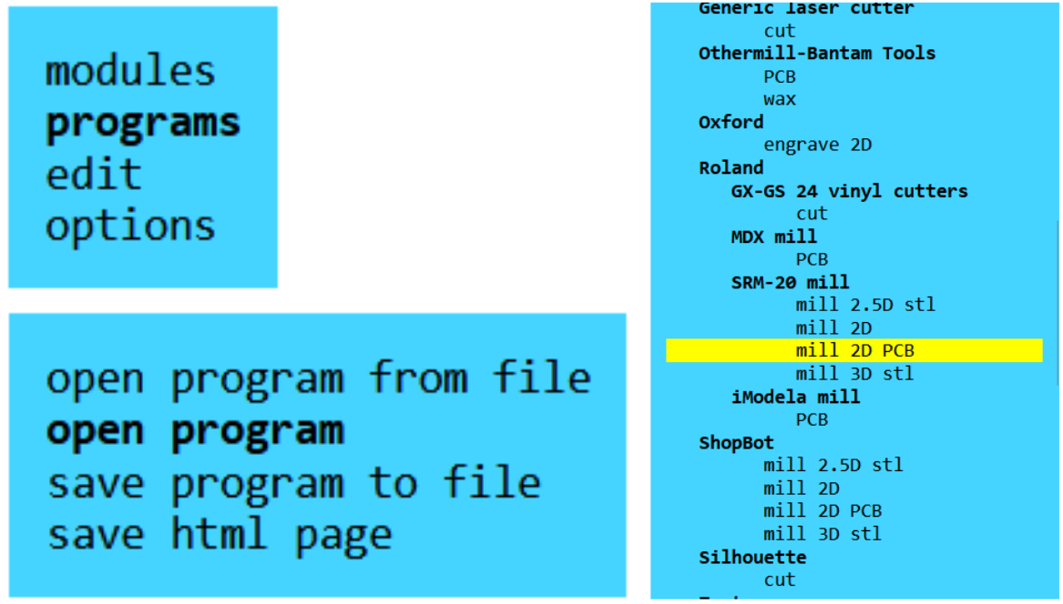
Repeat the same for the outline SVG:
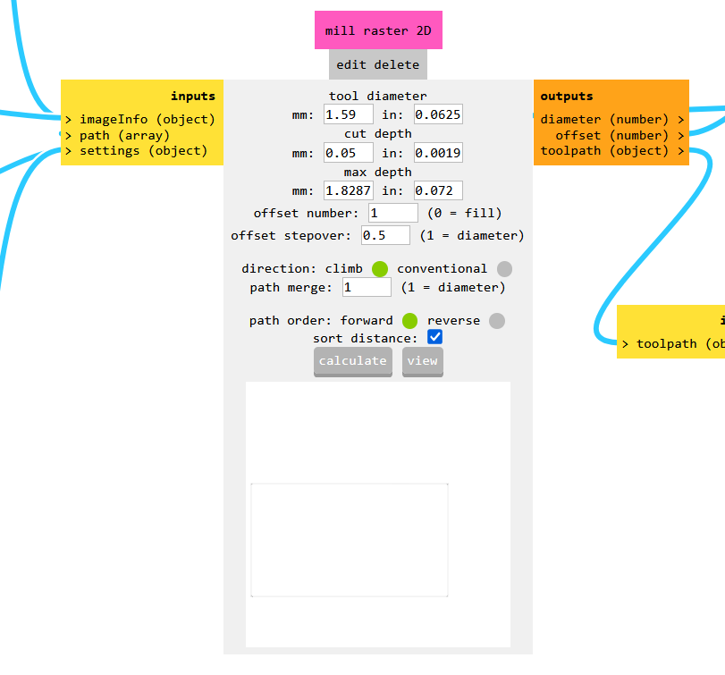
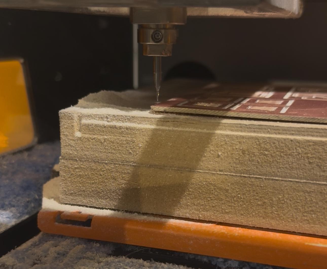
I used an FR4 board because it's sturdier and longer-lasting than FR1. My bit choices were:
To set up the Roland SRM-20:
Soldering went great. I used a TENMA Digital Solder Station and HiFlo Rosin-Activated Core Solder Wire. Here are the components I soldered:
| Component | Value/Type | Notes |
|---|---|---|
| Microcontroller | XIAO ESP32C3 | Through-hole headers |
| Grove Connectors | SMD 4-pin | Plug-and-play |
| Resistors | 0Ω, 100Ω, 10kΩ | Bridging, pull-up |
| LED | Green (SMD) | Feedback |
| Button | SMD push-button | Input testing |
I used a multimeter for continuity testing before powering the board. I checked all the power lines, the button, and LED paths.
Then I flashed the following code to test the LED and button:
#define LED_PIN 10
#define BUTTON_PIN 0

void setup() {
  pinMode(LED_PIN, OUTPUT);
  pinMode(BUTTON_PIN, INPUT_PULLUP);
}

void loop() {
  if (digitalRead(BUTTON_PIN) == LOW) {
    digitalWrite(LED_PIN, HIGH);
  } else {
    digitalWrite(LED_PIN, LOW);
  }
}
The test was successful — pressing the button turned the LED on!
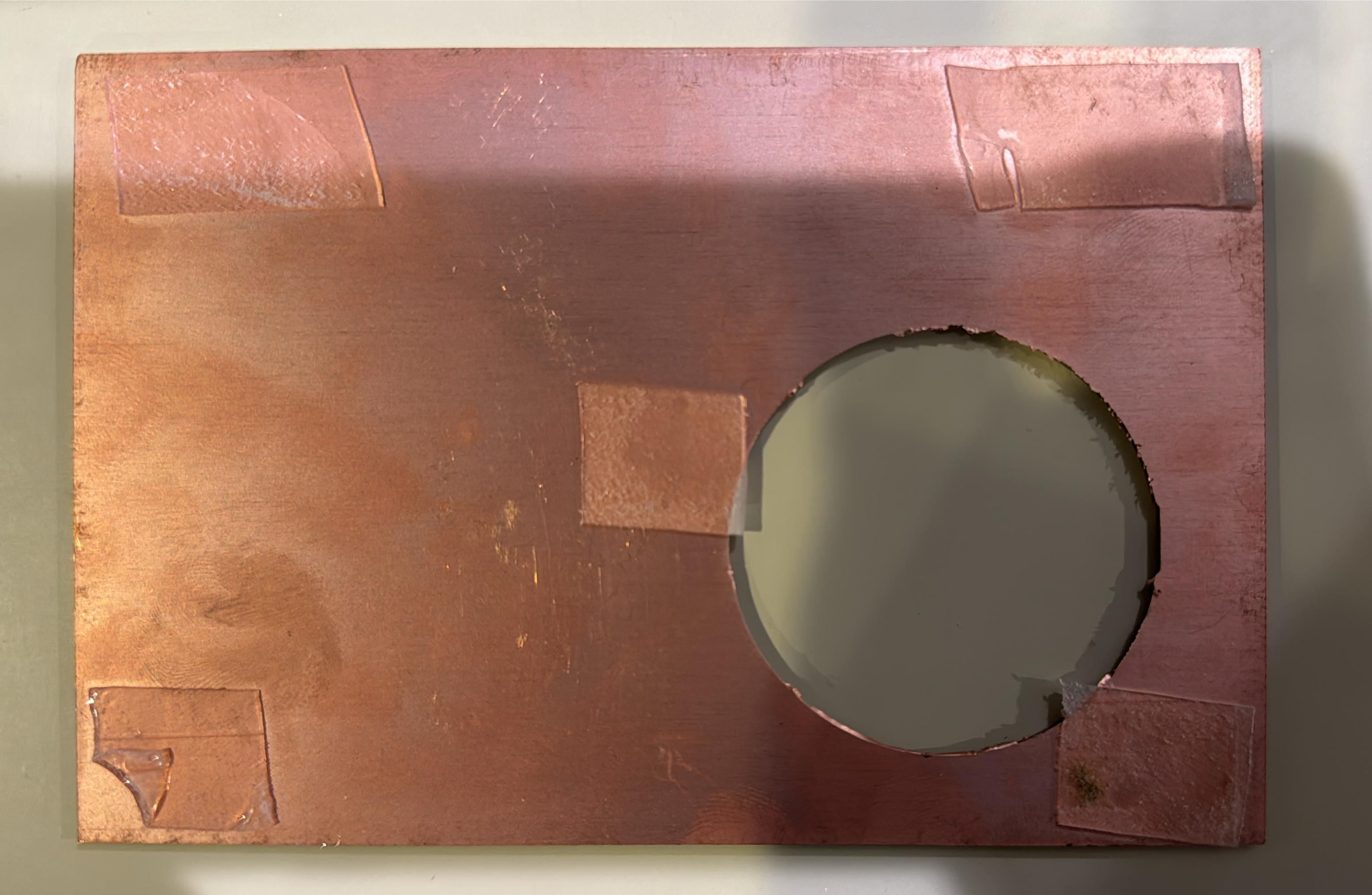
Nothing was wrong with the soldering or wiring, but I realized I should’ve matched my trace widths more closely to the bit size. Milling took a lot longer than expected because the machine had to trace each line multiple times at slow speed. Next time, I’ll:
grove_shield.kicad_sch – Schematic from KiCadgrove_shield.kicad_pcb – PCB layoutinner_mill.svg – For trace millingoutline_cut.svg – For outline cuttinginner_path.rml – Generated toolpath for tracesoutline_path.rml – Toolpath for cutting the boardled_button_test.ino – Test codeGrove_1x04-90Degree.kicad_mod – Custom SMD Grove connector footprintEverything is documented and organized for easy reuse, sharing, or improvement.