2. Computer Aided design
This week I worked on a variety of 2D and 3D design softwares.
2D
Cuttle
Cuttle is a 2D design tool on the web that allows you to make interesting 2D designs quickly.
Creating A Design On Cuttle
Note
Make sure you create an account on the Cuttle website to use their features.
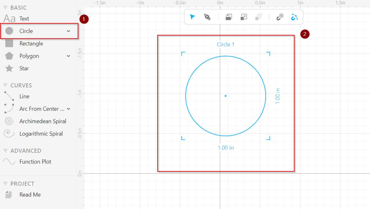
- Pick the Circle Tool from the toolbar
- Hold Ctrl then click and drag on the canvas to create a perfect circle.
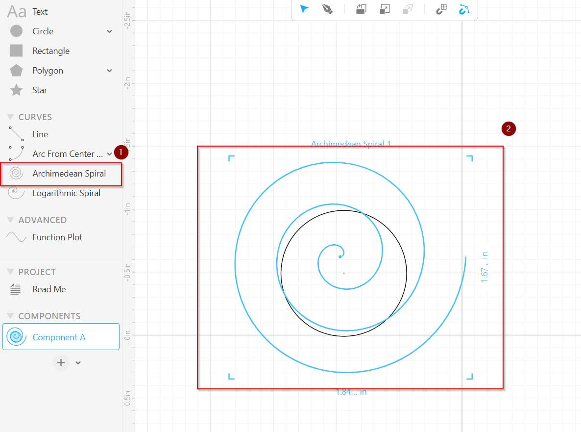
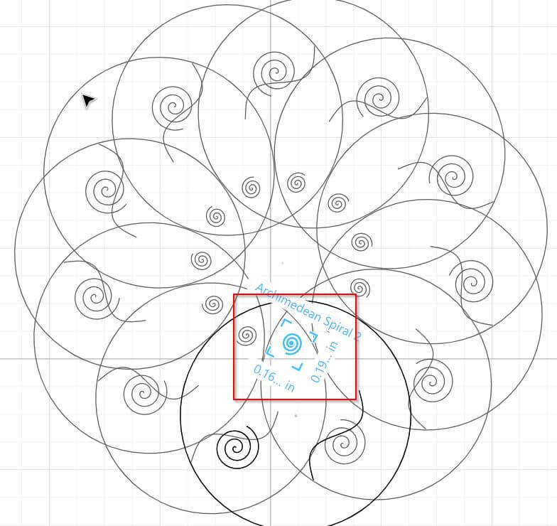
- Pick the Sprial Tool from the toolbar
- Hold Ctrl then click and drag on the canvas to create a Archimedean Spiral.
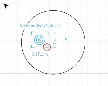
Tip
You can click and drag the corners of an object to resize it.
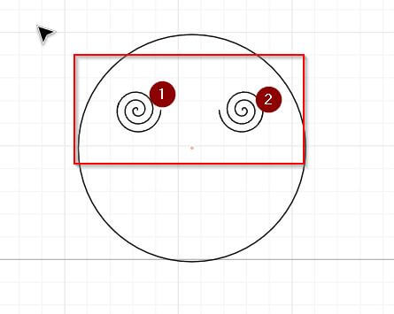
- Copy the spiral using Crtl C then press Crtl V to paste.
- [ Optional ] You can flip the other spiral horizonatly by using Crtl H
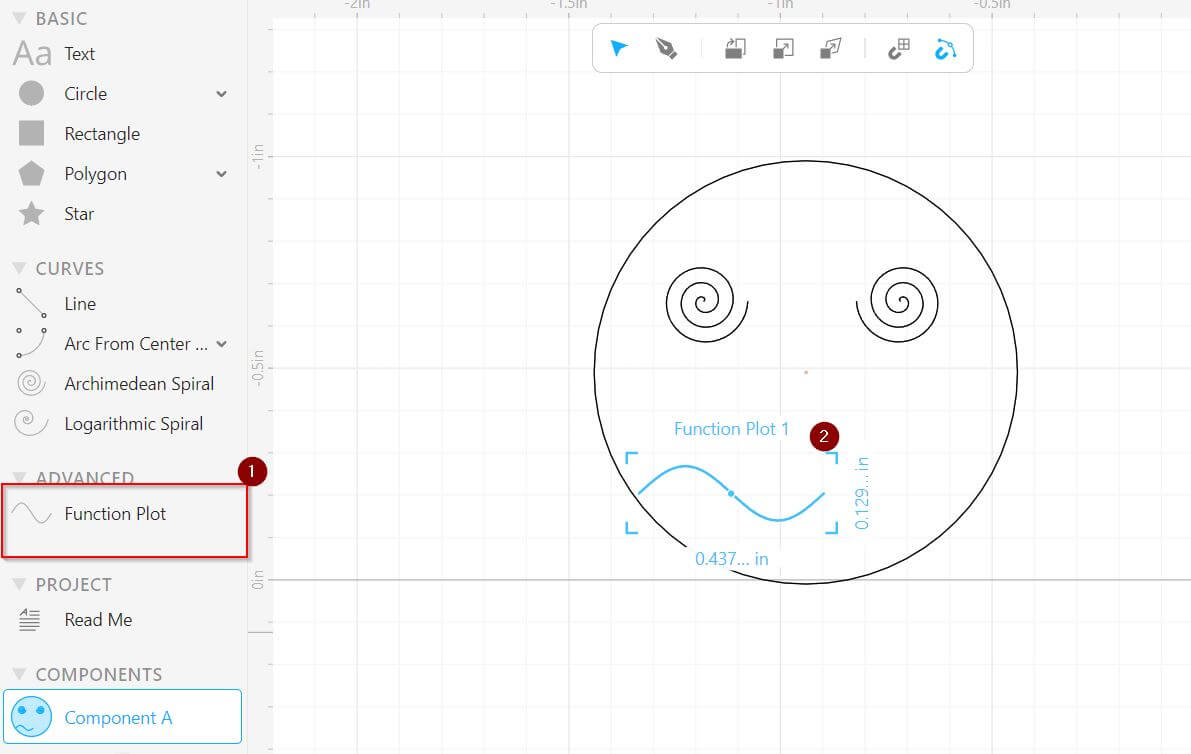
- Pick the Function Plot Tool from the toolbar
- Hold Ctrl then click and drag on the canvas to create a swigly line.
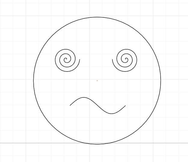
Success
If you did the steps correctly you should have a funny face like the one below. =)
Creating A Pattern
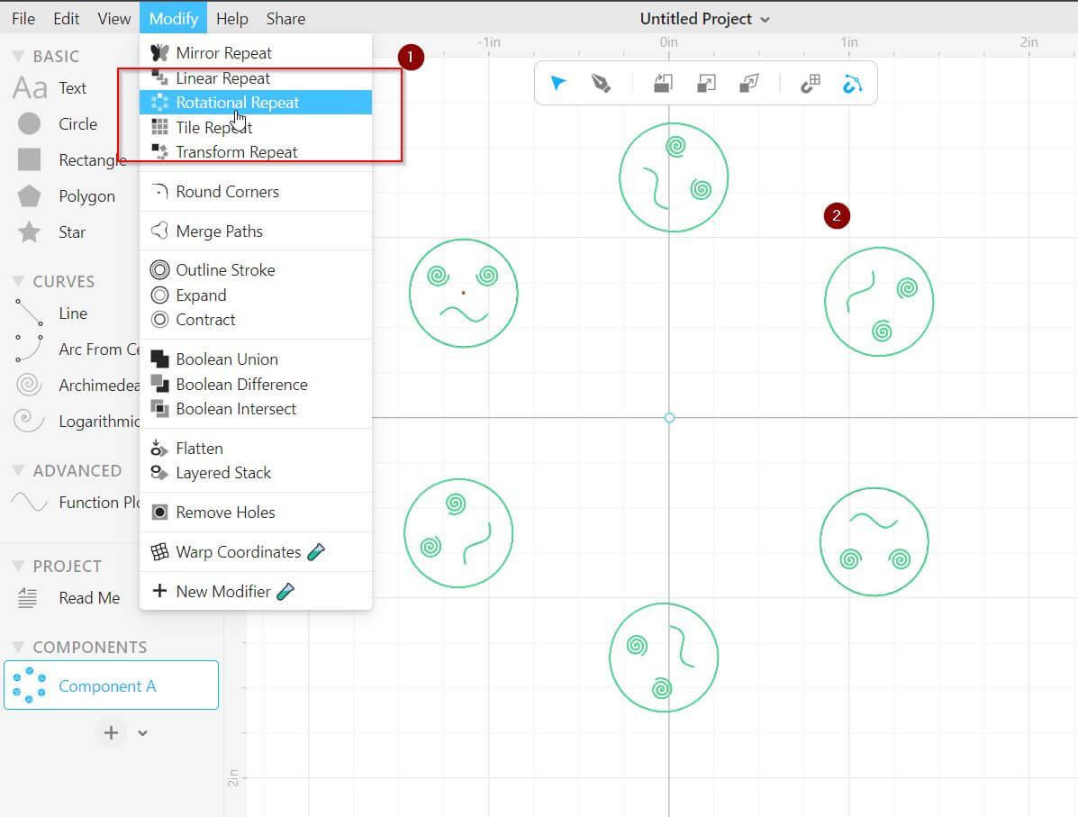
We can create a pattern from this design in several easy steps. First you want to repeat your design by using (1) Modify > Rotaional Repeat
You should see your design repeated several time in the shape of a circle (2) if the proccess was successful.
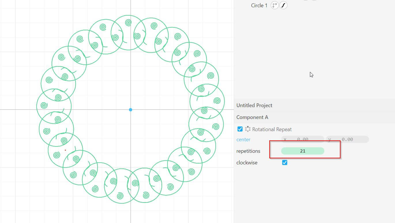
You can increase or decrease the number repetitions by adjusting the number highlided above.
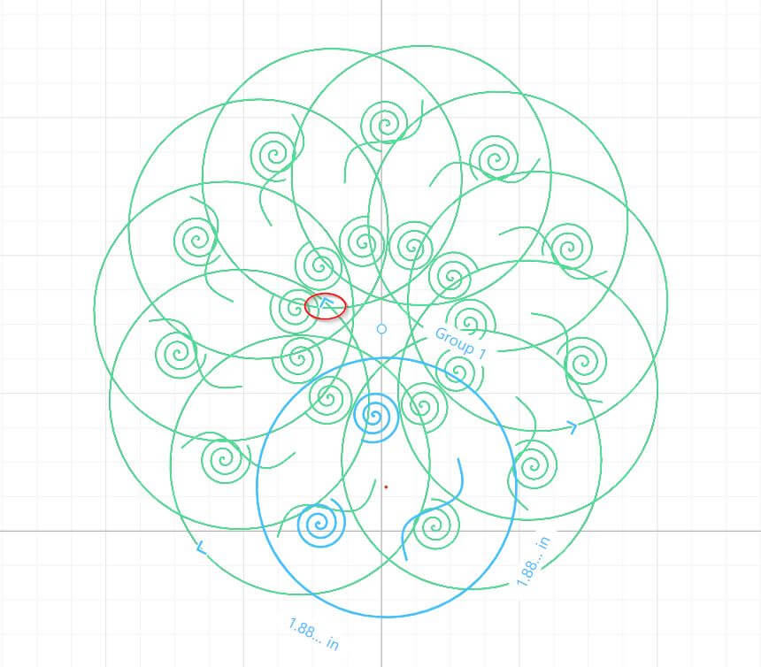
At the moment all of the designs are in green which means they are clones of the original design. Clicking on one of them will highlight the main design in blue.
We can resize the main design by using the corners highlighted in the image above. Since the rest of the designs are clones of the main one, they will change to match the original.
At the moment the pattern looks messy. We can fix it by adjusting individual elements such as the spiral in the image above to make it more appealing.
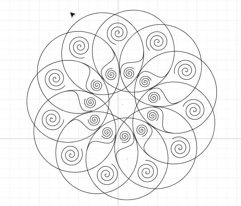
we can continue to resize elements until we have a pattern that we are satisfied with.
Success
At the end you should end up with something that looks like the image bellow.
You can download my design from here .
Inkscape
Generating Vector
Info
“Vector graphics are digital art that is rendered by a computer using a mathematical formula. Which means they can be scaled without losing any quality.
Raster images are made up of tiny pixels, making them resolution dependent and best used for creating photos”
I tried to test out the trace bitmap feature of inkscape that generates a vector image from a raster image.
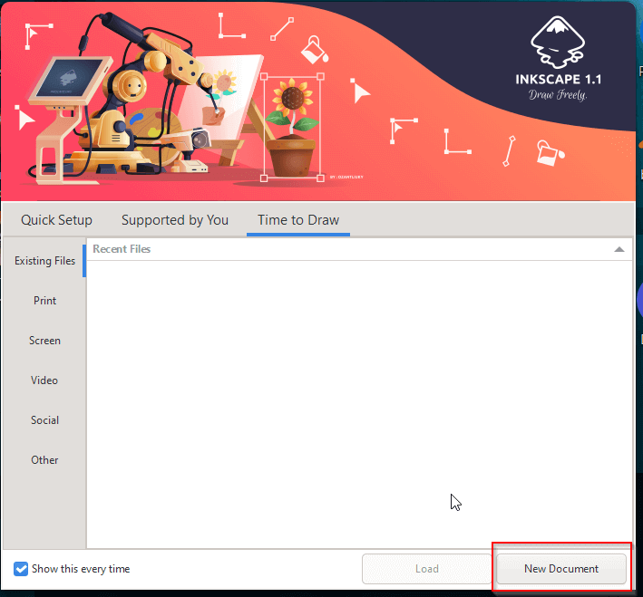
Start by creating a new document
copy and paste an image you want to convert
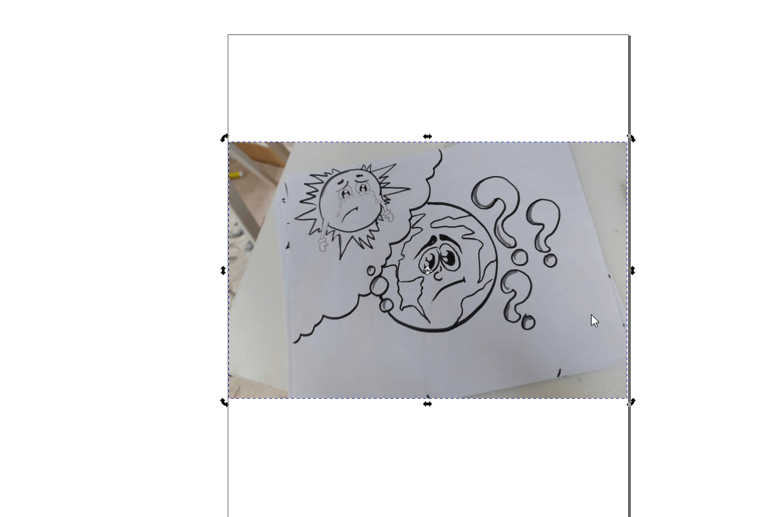
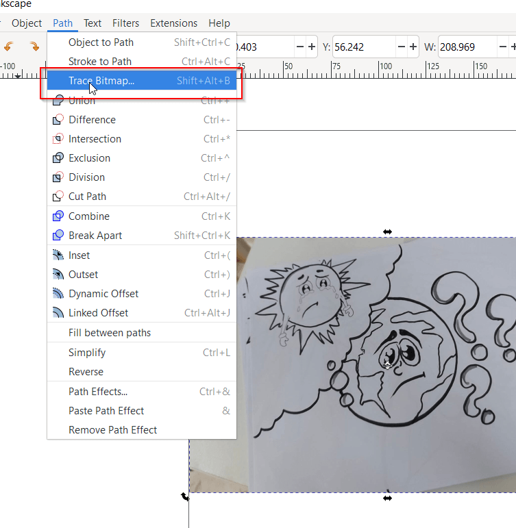
Select path > Trace Bitmap
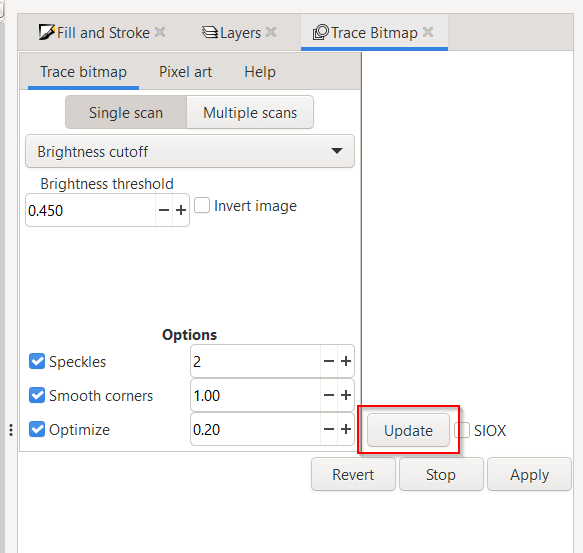
Click update to preview what the vector image will look like
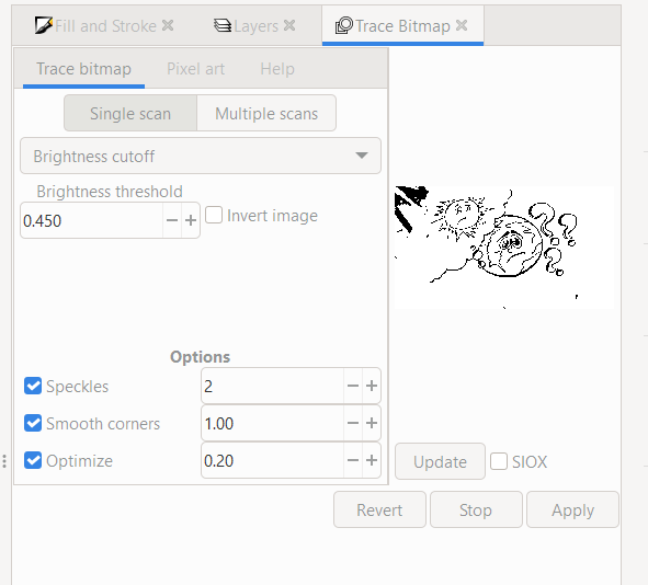
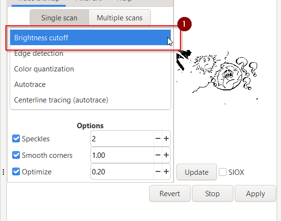
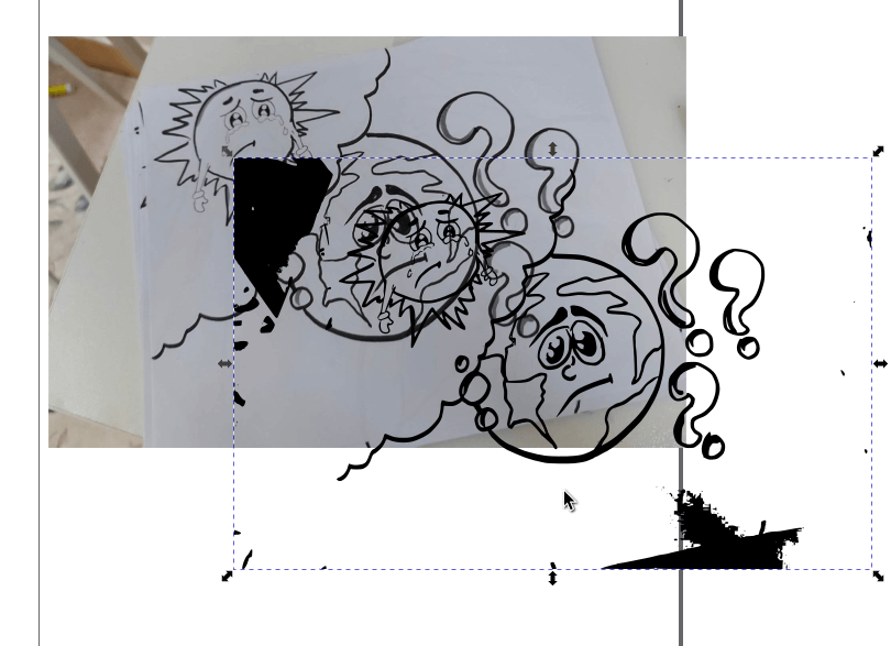
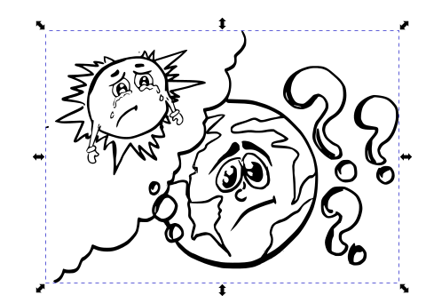
Sometimes i doesnt catch all the details of the original image, as you can see in the image below the lines are distorted and it did not capture details like the suns tears.
We can adjust Bitmap values to impove this. Each value changes a specific think about the image.
For instance we can select the brightness cuttoff option
Increase its value then update
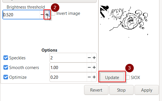
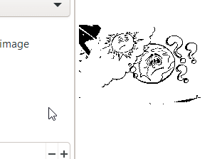
As you can see the lines are more defined now
Here is a basic table outlining what each value changes
| Value | Description |
|---|---|
| Brightness Cuttoff | Usesshades of gray of a pixel as an indicator of whether it should be considered black or white. |
| Edge Detection | Uses an edge detection algorithm as a way of quickly finding isoclines of similar contrast. |
| Color Quantization | Finds edges where colors change, even at equal brightness and contrast, then coverts them to either black or white. |
Once satisfied click apply
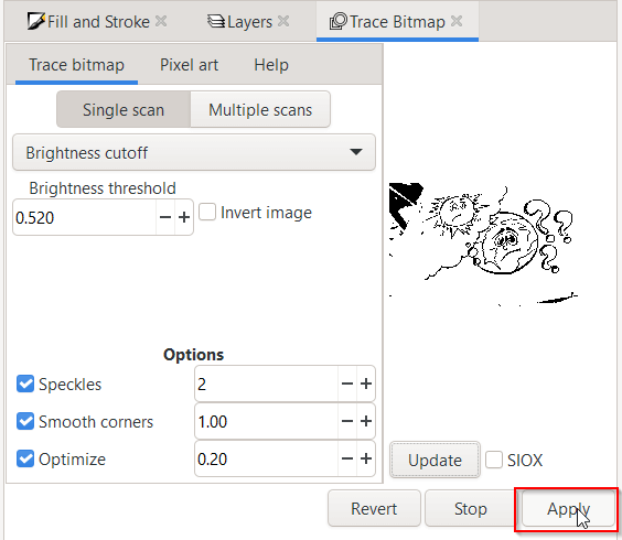
The vector image has been generated above the orginal image.
Edit and Color
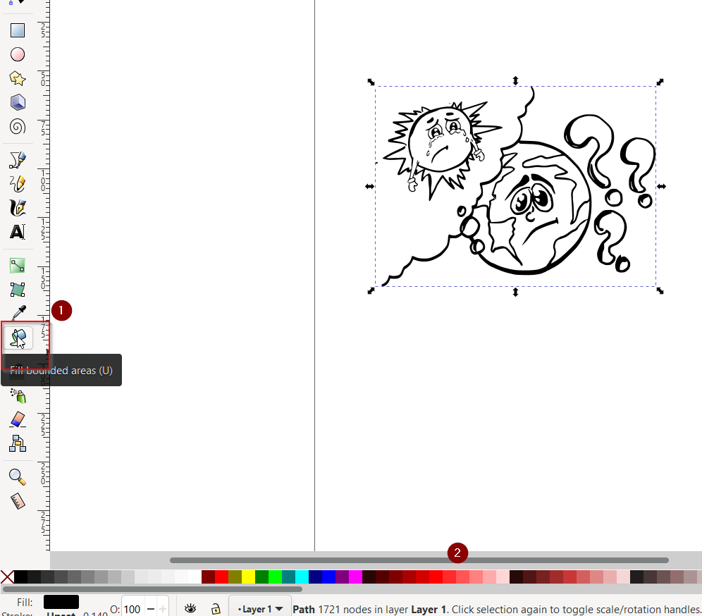
To remove the black parts of the design first select the Node Tool
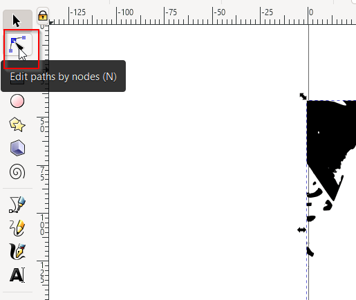
You well be able to see all the nodes in your vector image.
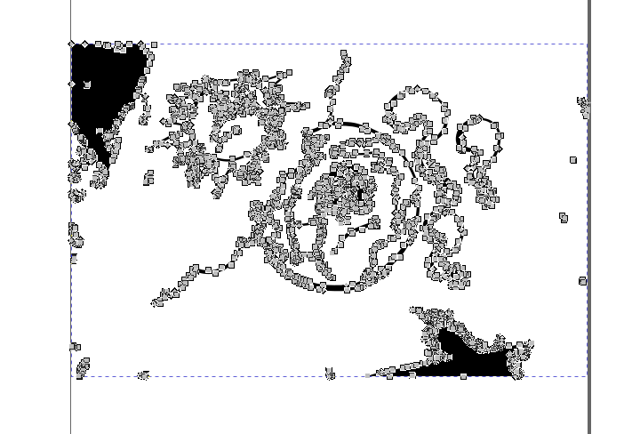
Highlight all the nodes you dont want Then press Delete on your keyboard.
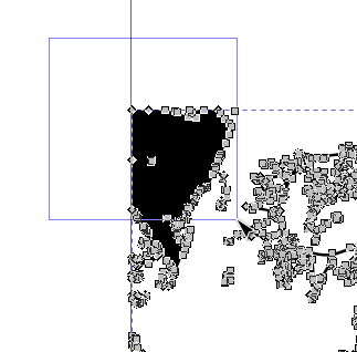
Continue to delete nodes until you are statisfied with the resualt
To color the design select the Fill Tool then a color form the colors found at the bottom. Click on an area you would like to color and the tool will fill that area.
Final Result
this is the final result

You can download my design from here .
3D
TinkerCAD
TinkerCAD is a 3D design software that runs on the web browser, you can access their website by using the following link.
For this design software I am going to try to make my pixel art character 3D.

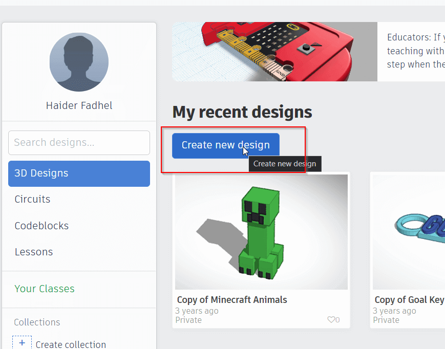
First I opened the tikerCAD website and logged in using my Gmail account.
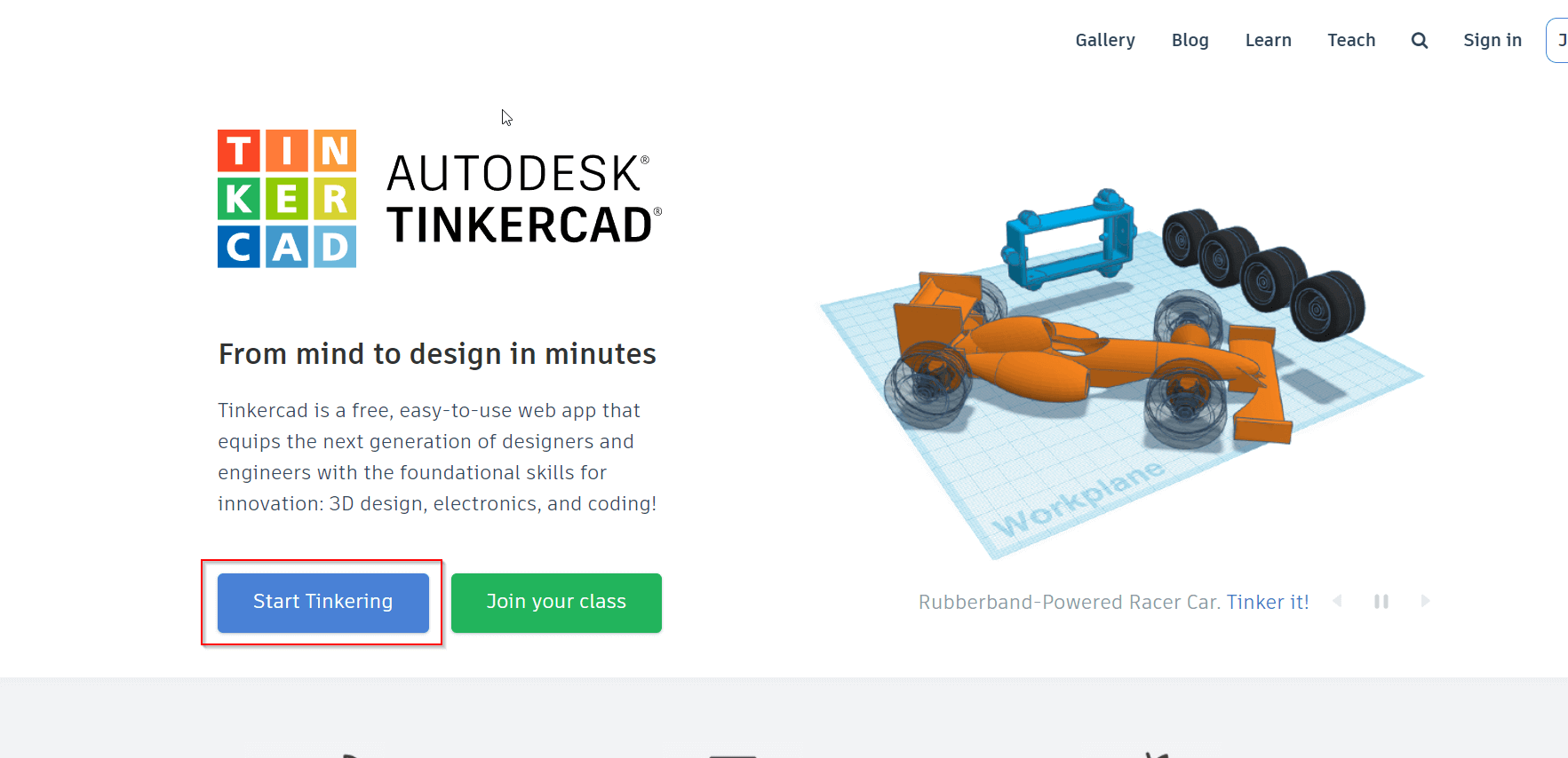
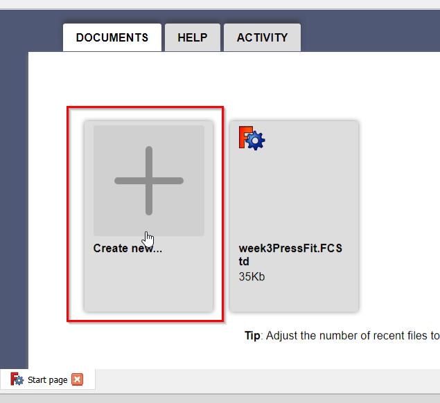
I clicked Create New Design.
Use the Box Tool to create a platform.
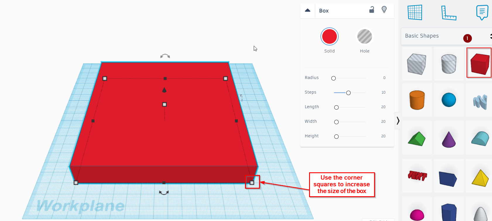
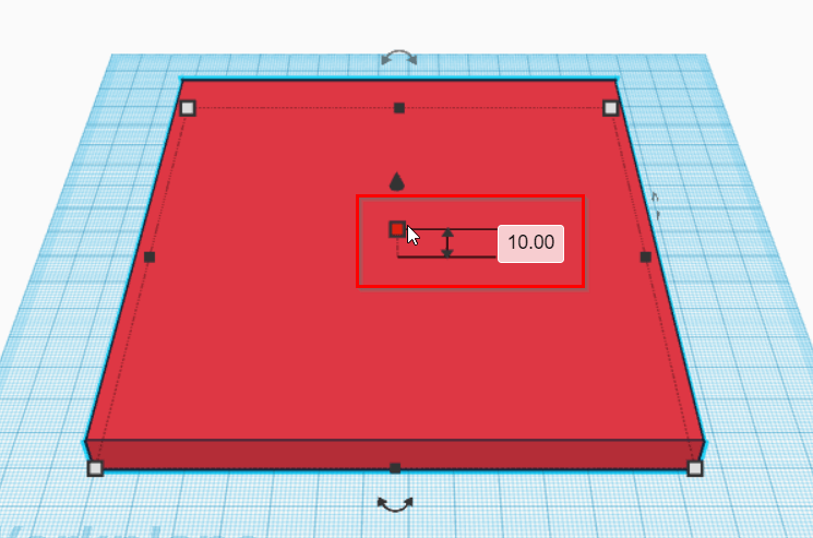
I used the middle square to adjust the platform height.
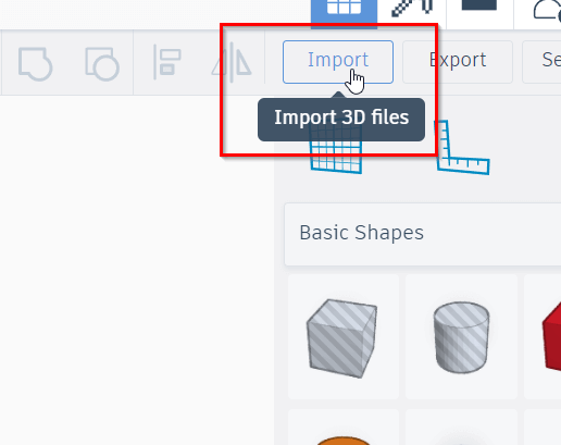
I converted my artwork to an SVG format so that I can import it in TinkerCad.
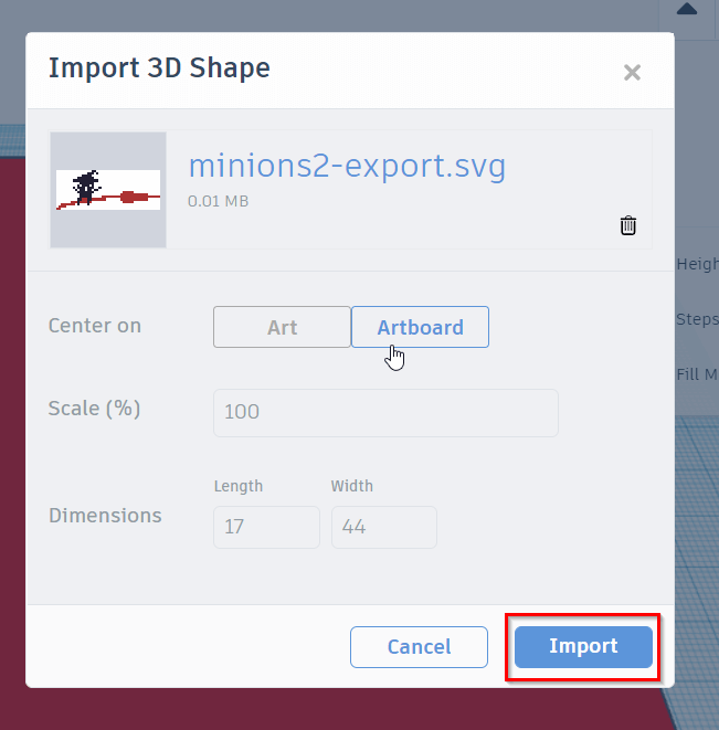
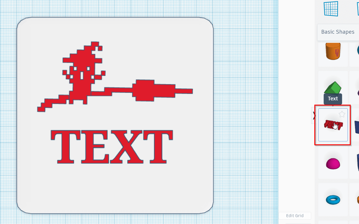
I Clikced the Import button in the top right of the screen.
I then selected the SVG file.
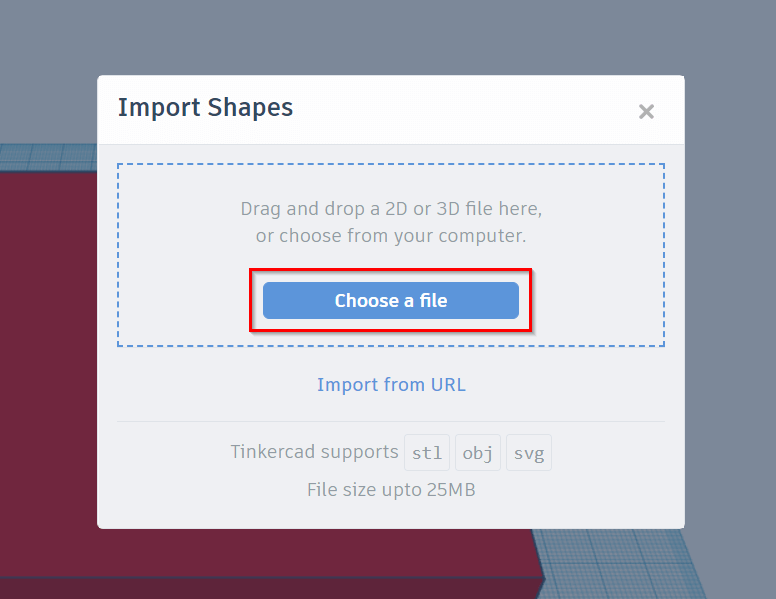
Finally I clicked Import to add my artwork to the canvas.
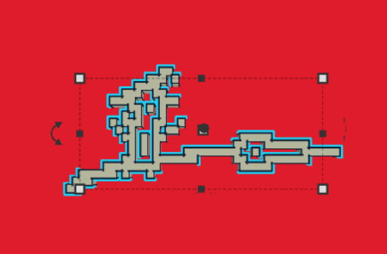
I noticed that there were some issues with the importing proccess.
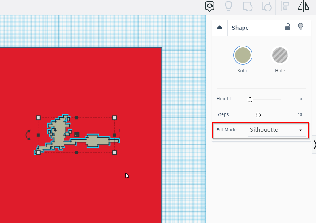
To fix this i first changed the fill mode to silouette.
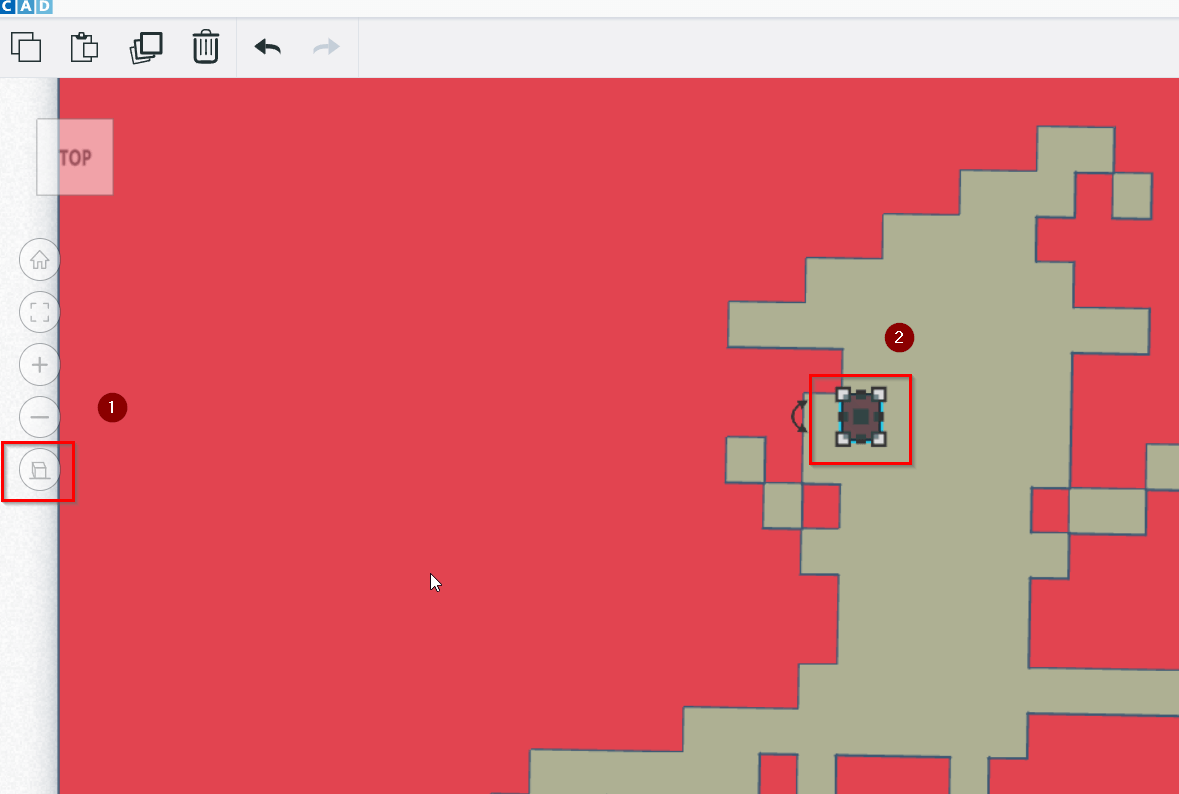
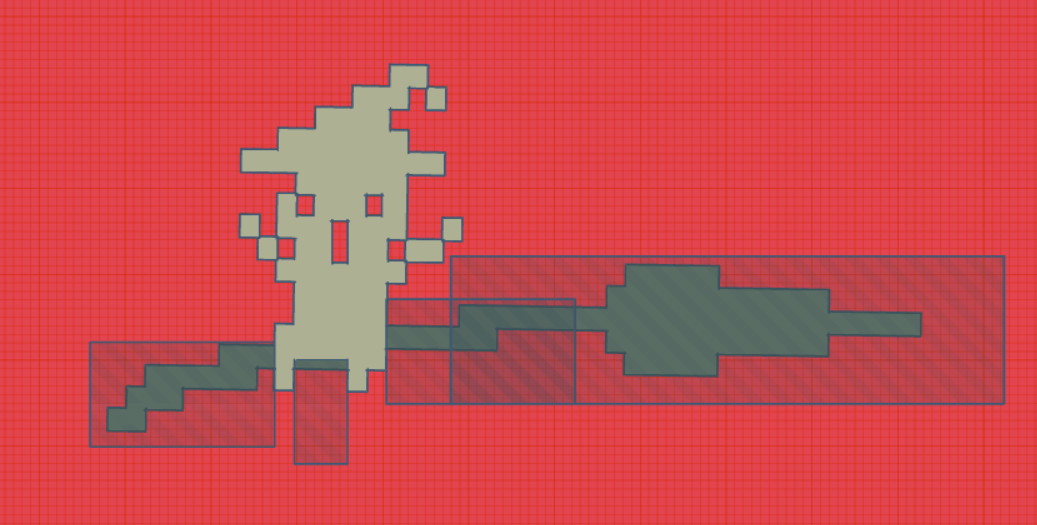
I grabbed an empty box to create holes in the design.
I also want to adjust the sizes of different elements so that the model isnt just a flat surface.
![]()
I clicked on the perspective button to so that i can adjust the size of the empty box in 2d (to better fit the design).
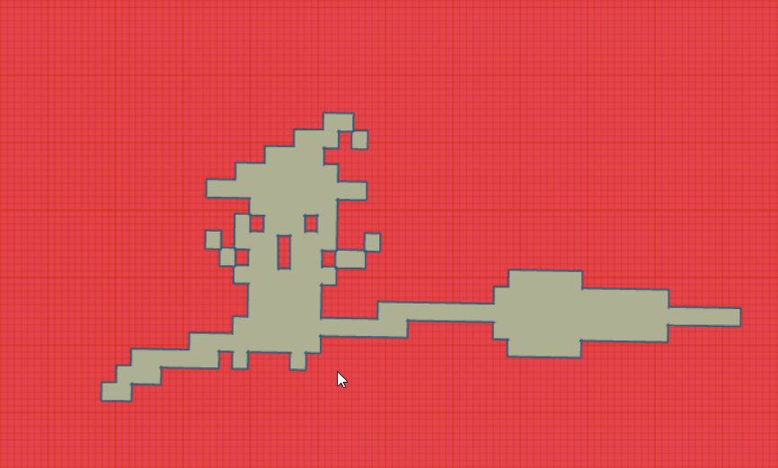
I copy pasted the empty box to create the face then I selected all the elements and clicked Group.
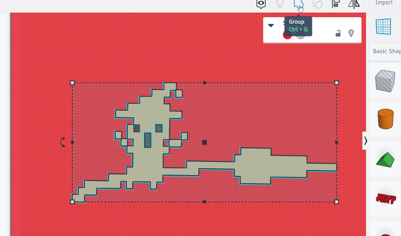
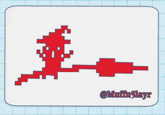
After grouping the artwork looks more like the image.
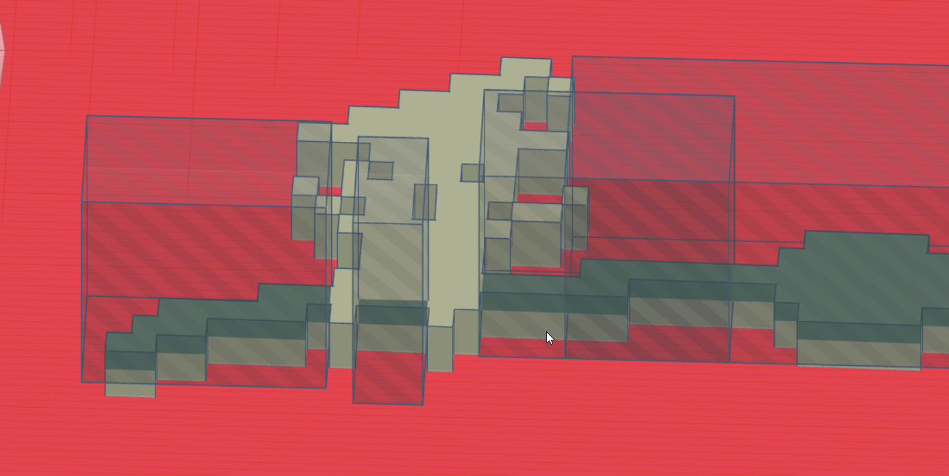
Next i tried to reduce the height in some areas to give the 3D model more depth.
I added a text element using the Text Tool .
After some minor adjustments this is the final product.
You can download my design from here .
freeCAD
To better familarize myself with freeCAD i used the yputube tutorial below.
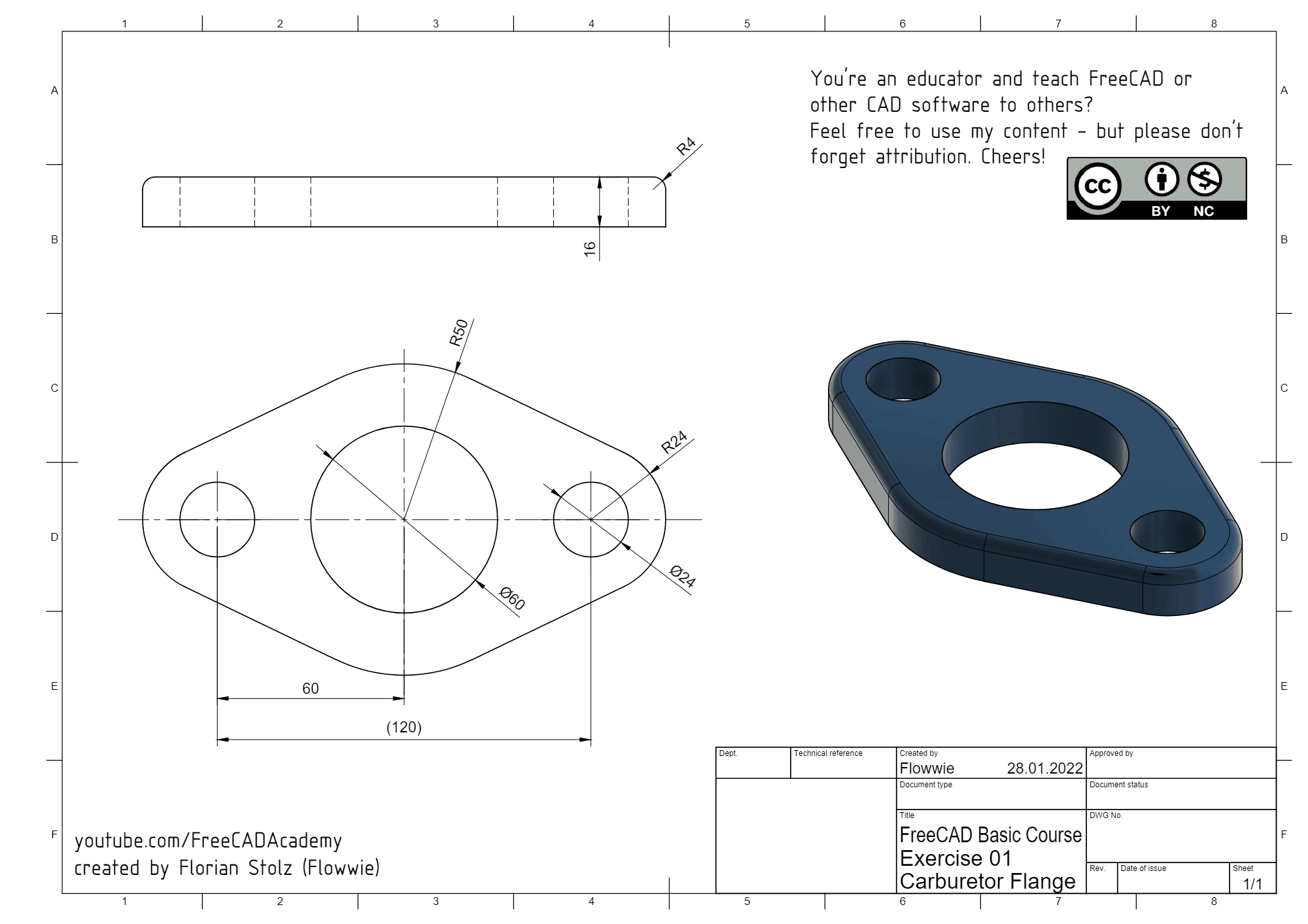
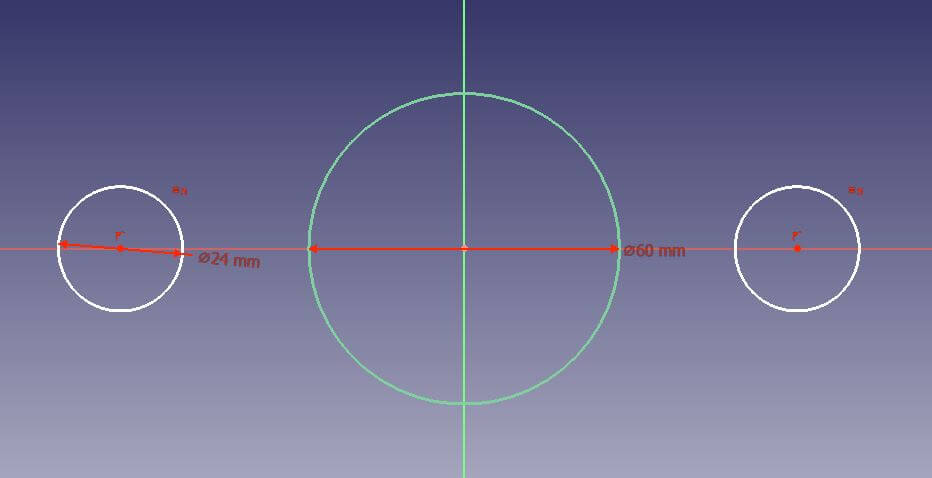
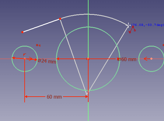
The objective of this tutorial is to create the following part. Below is a design diagram of the part’s dimentions.
Setup
First I created a new project.
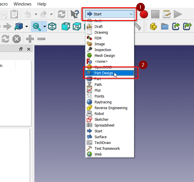
Then I seleceted the Part Design Workspace
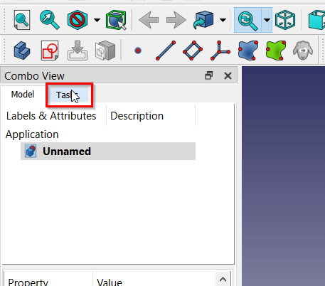
I selected the Tasks Tab from the Combo View
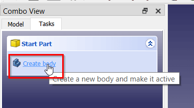
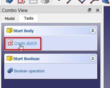
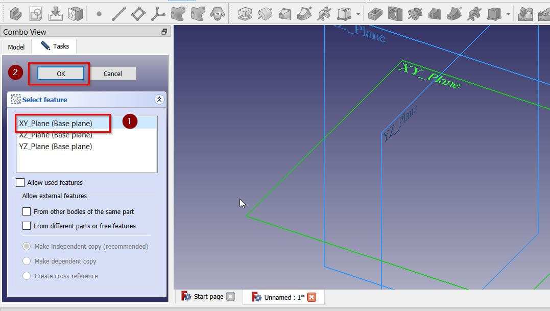
I clicked Create Body then Create Sketch
I selected the XY Plane the clicked OK
Sketch
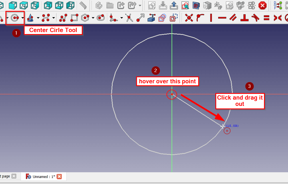
With the Center Cirle Tool selected, I hovered on top of the center point until it turned yellow then i clicked and dragged the point to create a circle.
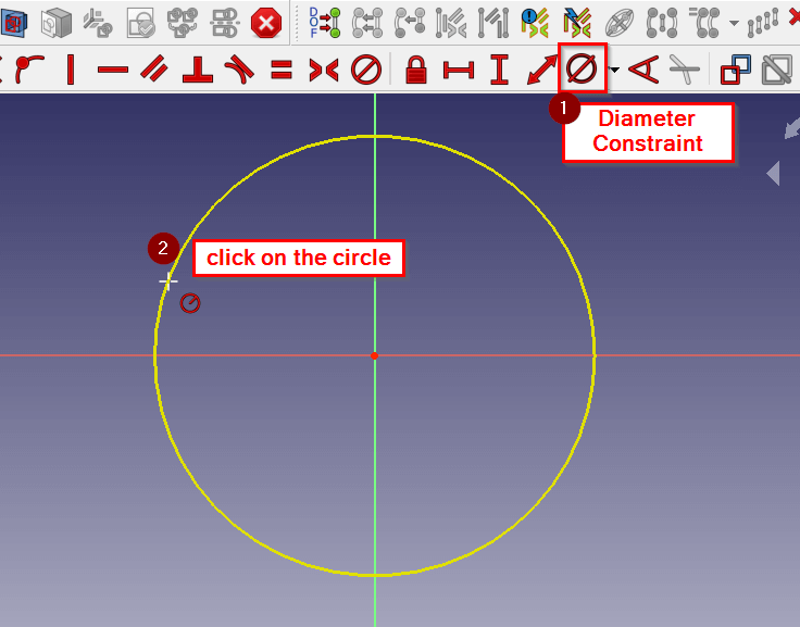
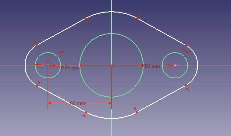
Using the Diameter Constraint, I was able to set the Diameter of the circle. I first selected the constraint then the circle.
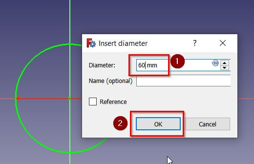
I set the Diameter to 60 mm to match the design document.
I repeated the steps above to create two more circles. Each of the smaller circles has a diameter of 24 mm.
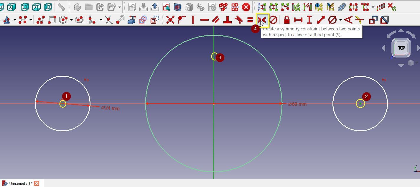
To center the two circles, I first selected the center point of the two circles then the line intersecting the circle in the middle and finally clicked the Symmetry Constraint
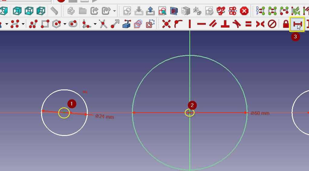
I used the Horizontal Distance Constraint in a similar way to set the distance between the circles. I set the distance to 60 mm.
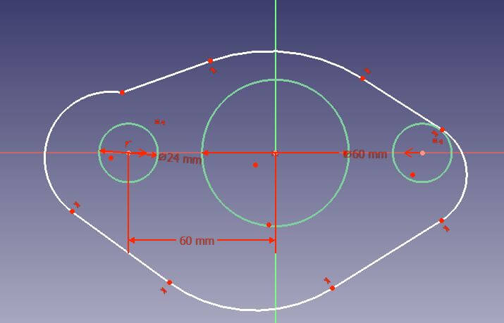
To create the outer area of the part, I first selected the Polyline Tool.
I started with a simple line.
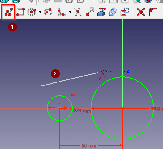
I clicked M on my keyboard to create an arc.
I was able to create this shape using lines and arcs.
To fix the shape of the part we need to add some more constraints.
First we’ll add a Tangent Constraint to join the last and first line of the shape. This constraint was added to the other lines automatically.

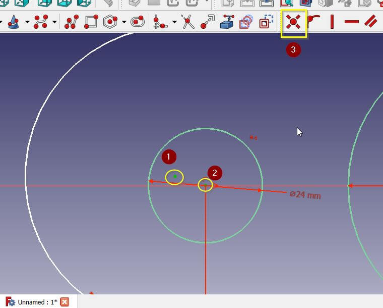
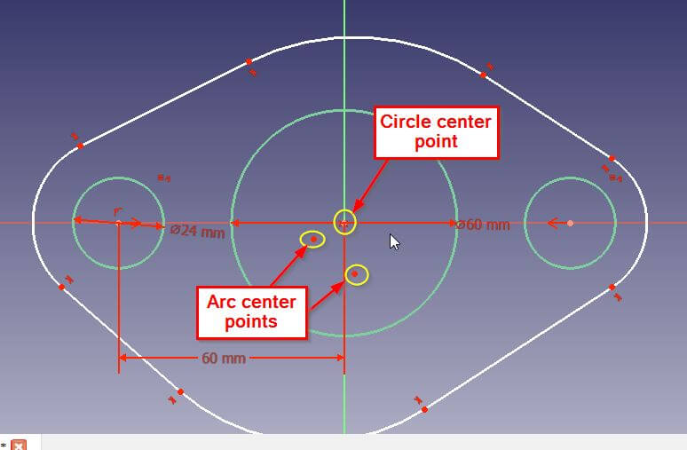
Next we will adjust the two Arcs on the sides so that they have the same center point as the small circles.
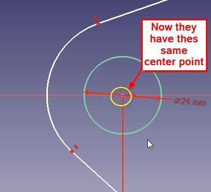
To do this click on both the center point of the arc and the one for the circle then use the Coincident Constraint.
Now it looks alot better , do the same for the other side.
We can do the same with the top and bottom Arcs and align them with the big circle.
After moving the points a little I ended up with something like this
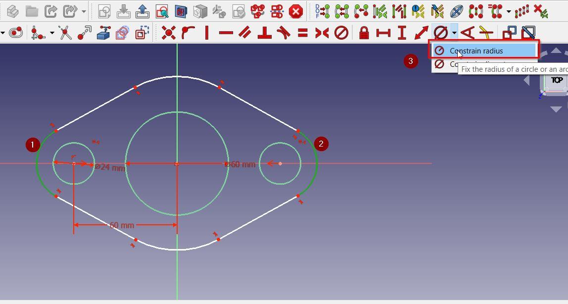
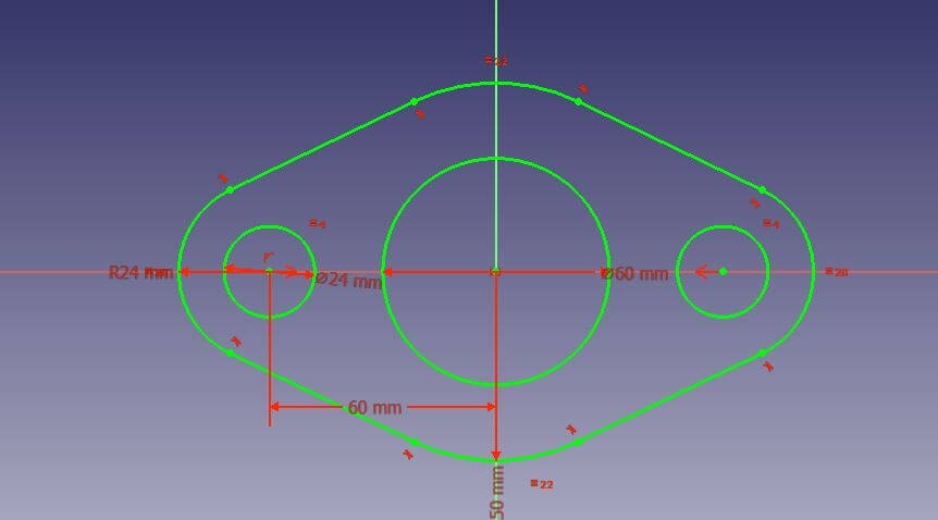
Last thing we need to do is set the radius of the arcs. To do this we click on the two side arcs then the Radius Constraint. (set it to 24 mm)
After doing the same for the top and bottom arcs (set them to 50 mm), the lines will be all green which means our sketch is fully constrained and ready for the next step.
3D Work
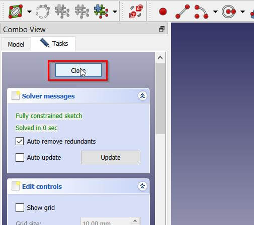
First close the sketch view
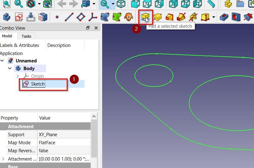
click the sketch file then the Pad Tool.
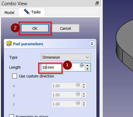
Set the length of the pad to 16 mm then press OK.
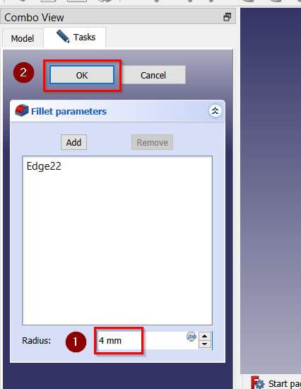
Lastly to round the corners click on one edge then click the Fillet Tool
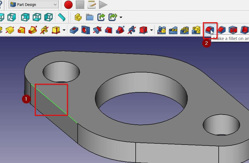
Set the radius of the fillet to 4 mm then press OK.
Final Resault
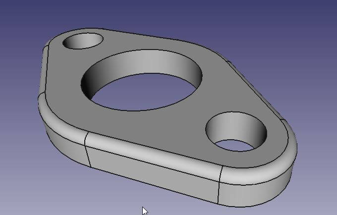
You can download the CAD files from here