6. Large format CNC (computer controlled Machining)
This week I worked on defining my final project idea and started to getting used to the documentation process.
Group Assignment
You can acccess the group assignment from here.
Individual Assignment
Idea
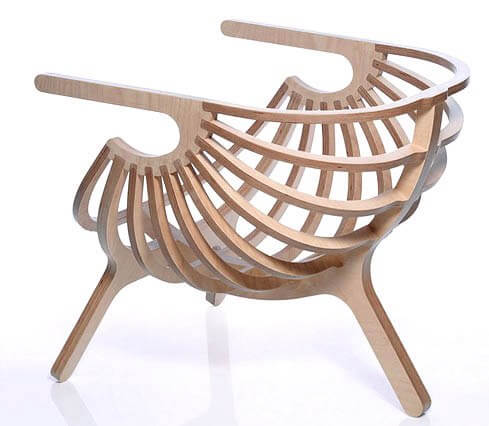
For my CNC project i was inspired by this chair i found on google images.
I tried to make it in freeCAD but i wasnt able to create it in time. I found it difficult to make parts in freeCAD so i choose to learn fusion 360 and try a simplier design.
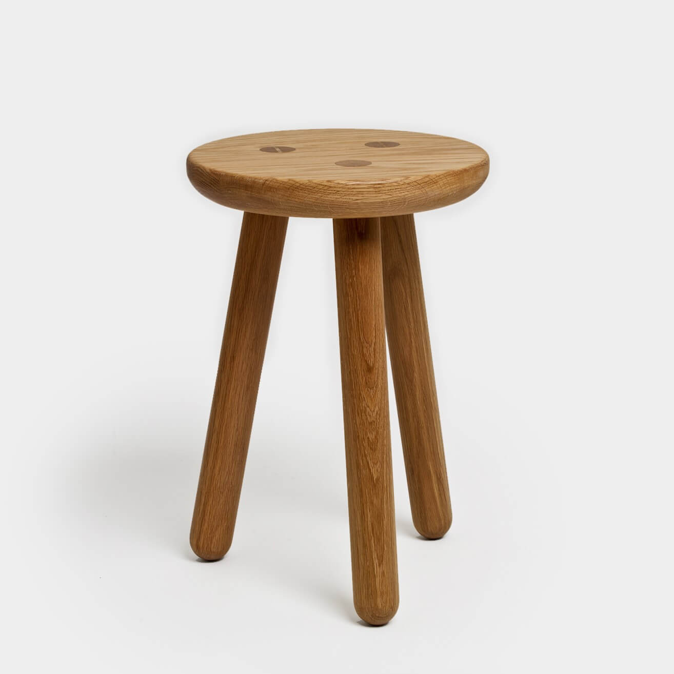
I choose to make a simple stool.
Design
To create the stool and learn more about using fusion 360 i followed this Youtube tutorial.
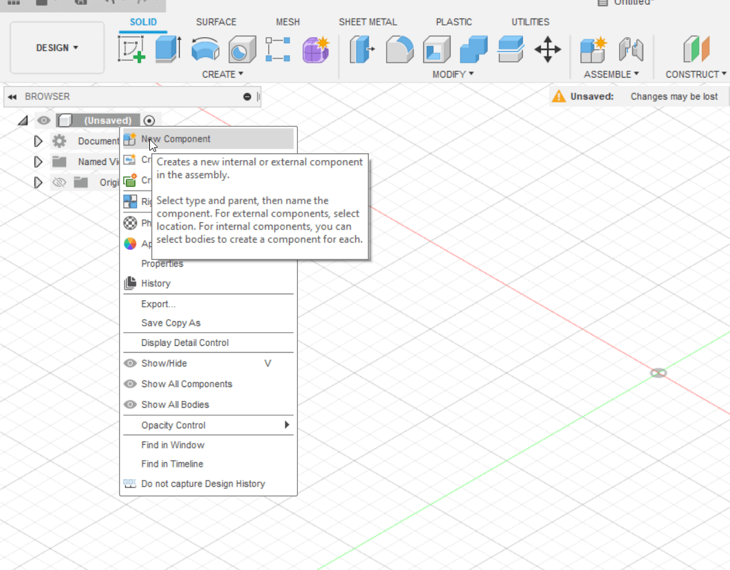
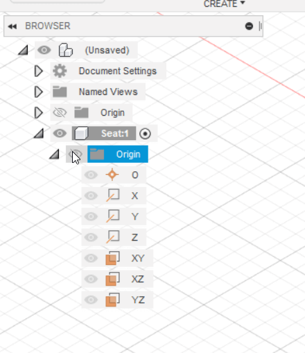
First I right clicked the project file and created a new component for the seat of my stool.
I make the origin folder visible.
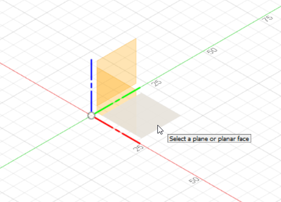
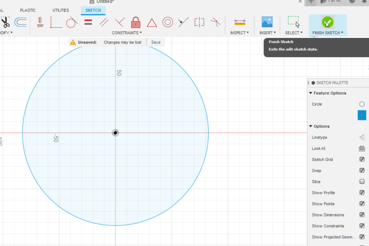
I create a sketch on the bottom plane.
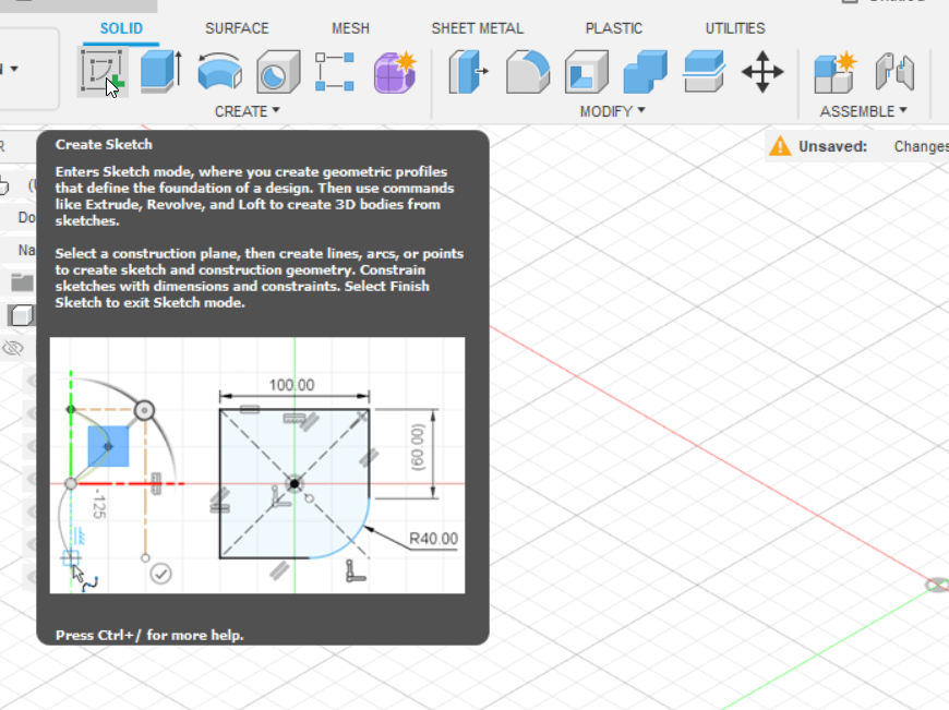
I use the circle tool to create a 14 in diameter circle.
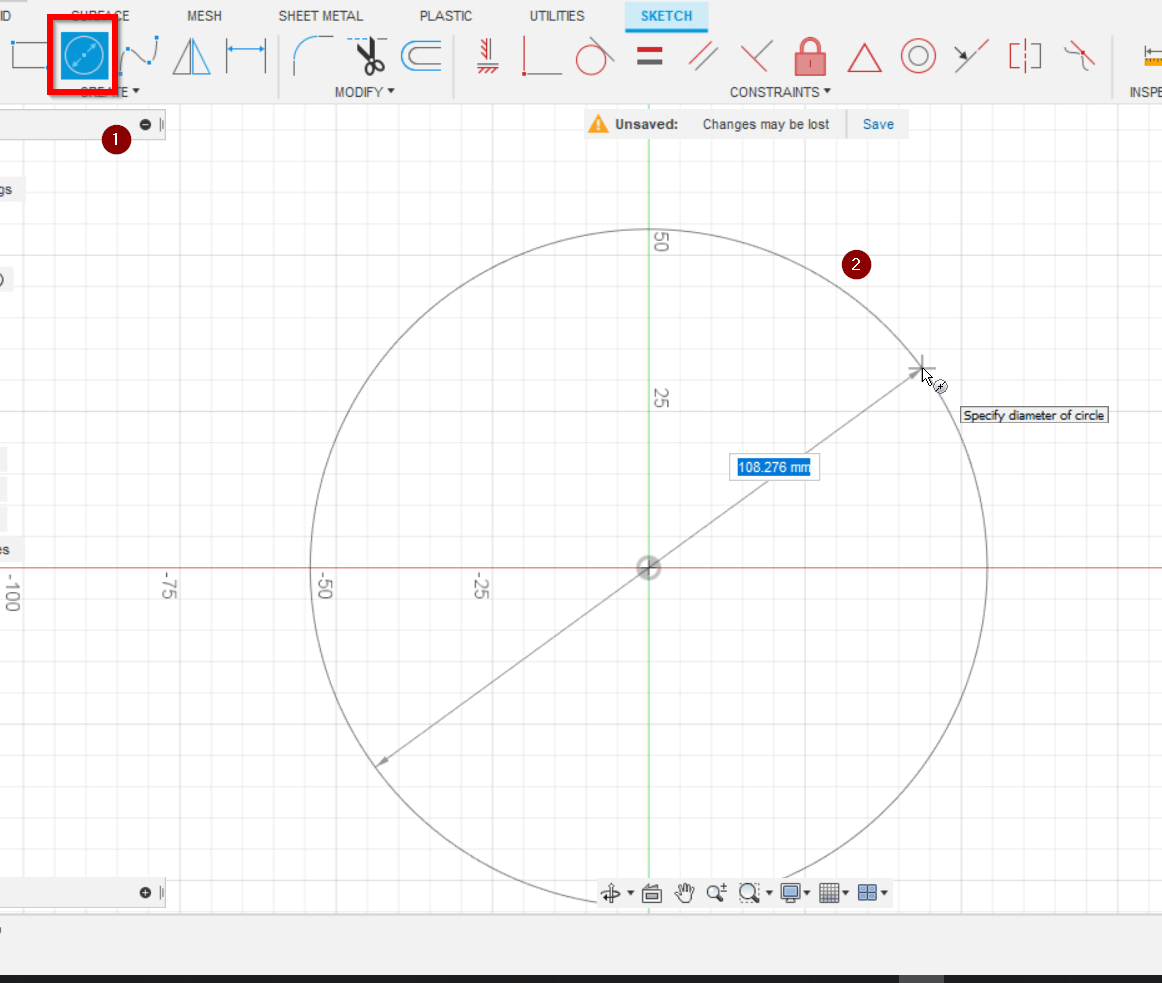
I click finish sketch to come back to the 3D tools
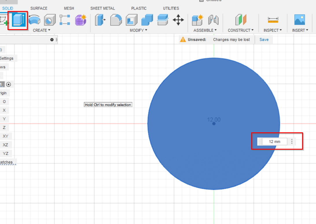
I use the extrude tool to add depth to the circle , i used 12 mm here but it depends on the type of material you are going to use.
I can now create some parameters in the parametric table so that the measurements can be easily adjusted. To access the parametric table I click on modify then I select the second to last option.
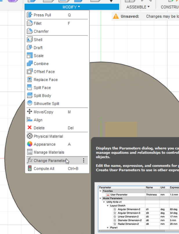
Any parameters you add will be in the User parameters section and all of the models parameters will be automatically added under Model parameters.
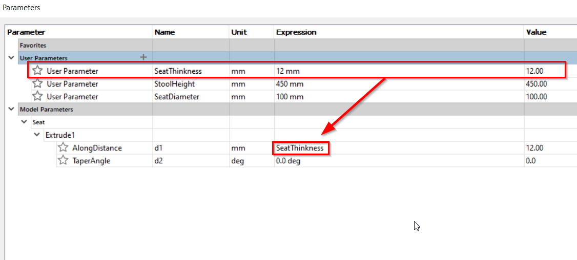
So to make the design parametric we simply replace the values in model parameters with our user parameters. In the example below the extrude value of the seat was changed from 12mm to the user parameter “SeatThickness”.
Create a new component for the leg on the side plane. You should be able to see the seat component in the sketch. Use the project tool and click on the seat component. We can now see lines that represtent that componet.
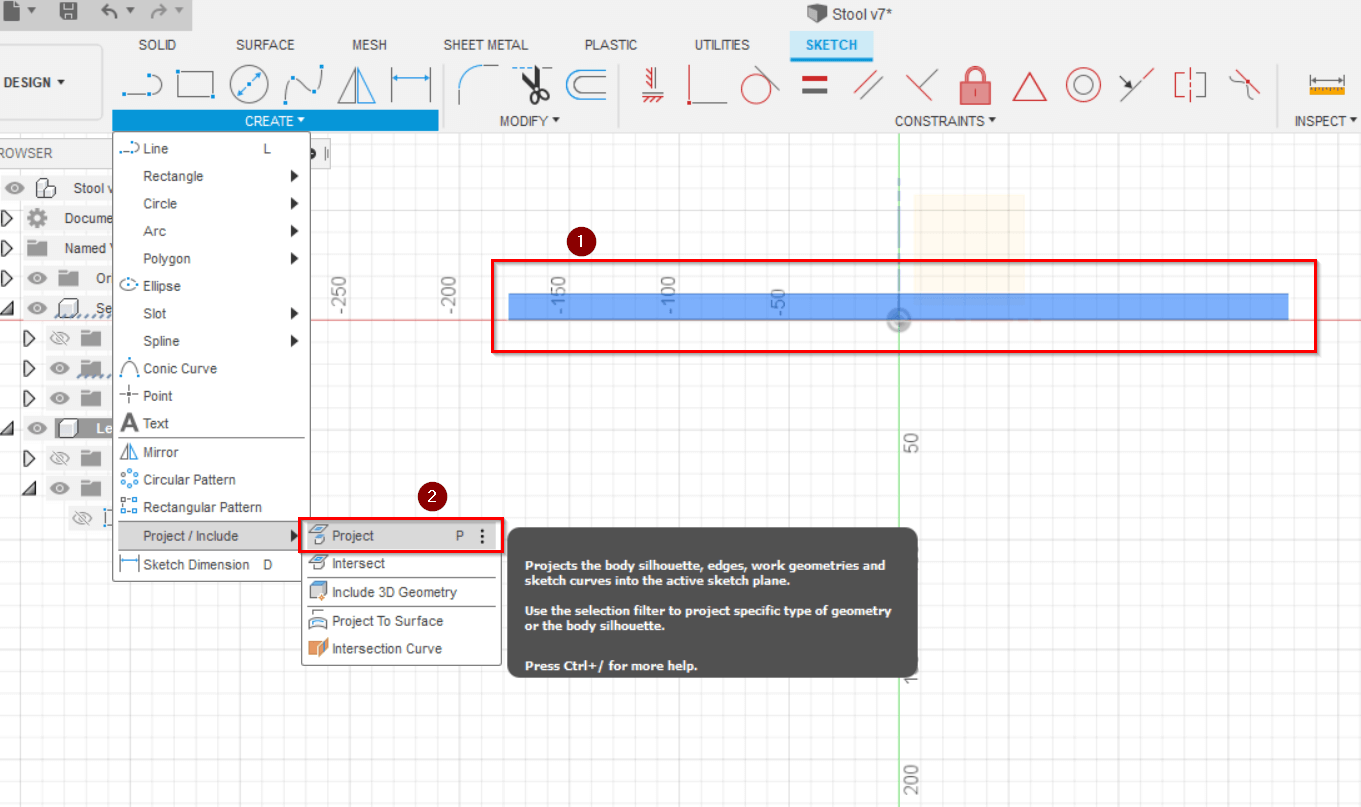
We can now use those lines to create a part that perfectly fits in the seat.
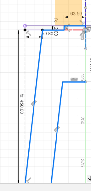
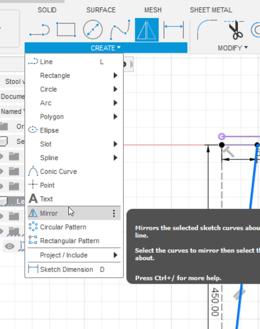
We can use the mirror tool to create the other side of the leg.
we select all the the sides of the leg as objects then the middle construction line as the mirror line.
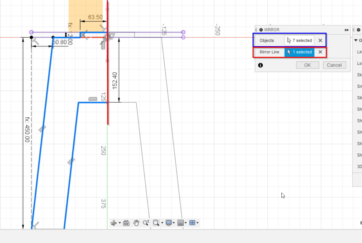
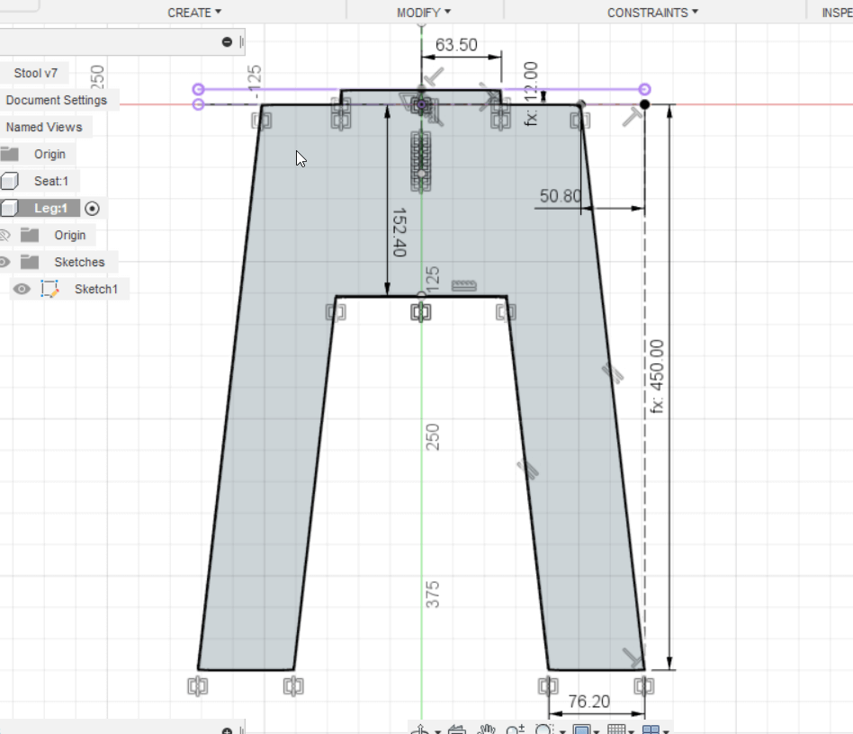
Click finish sketch and you should have something like the image below.
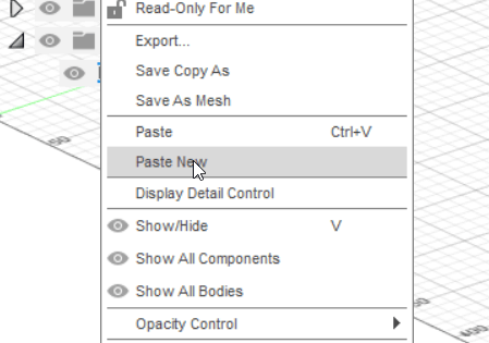
We can copy the leg we made and select paste new. The difference between paste new and normal paste is that regular pasting a component will make it linked with the other component. So any changes with one leg will affect the other one. Since our legs will have different joints its important to use paste new.
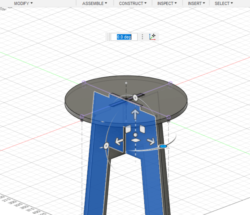
Click on the new leg component then right click and use the move fuction.
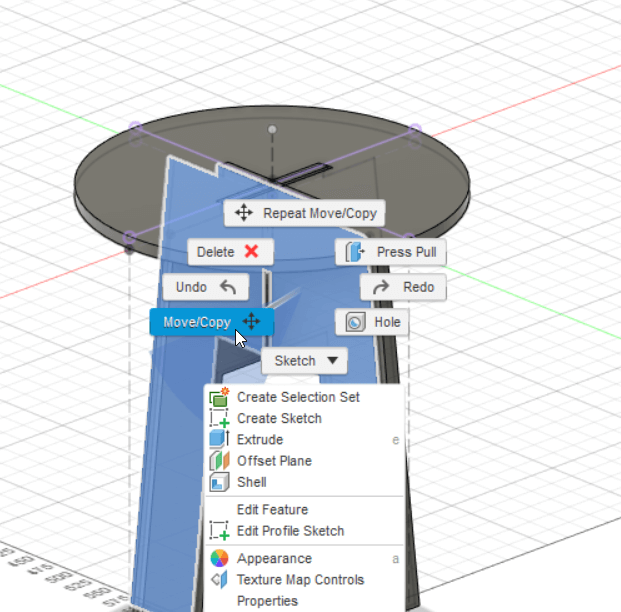
Move the leg until it is at a 90 degree angle from the other leg.
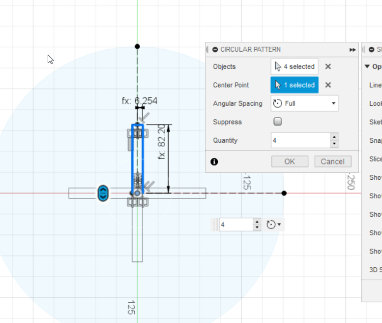
To create the joints that hold the stool together we’ll edit the seat component and add a rectangle in the middle. We can mirror the shape 4 times using the circular pattern tool.
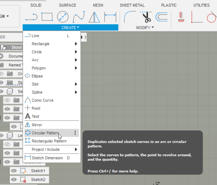
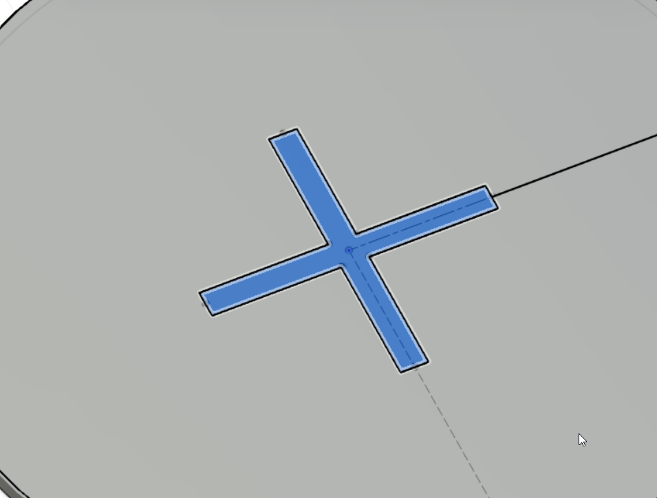
We select the sides of the rectangle then select the middle of the seat as the center point. By setting the quatity to 4 we can create a “+” shape.
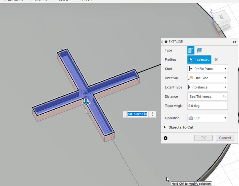
select the new shape then click the extrude tool.
To make a cut out of the seat using this shape we can extrude it by the negative value of the seat thinkness.
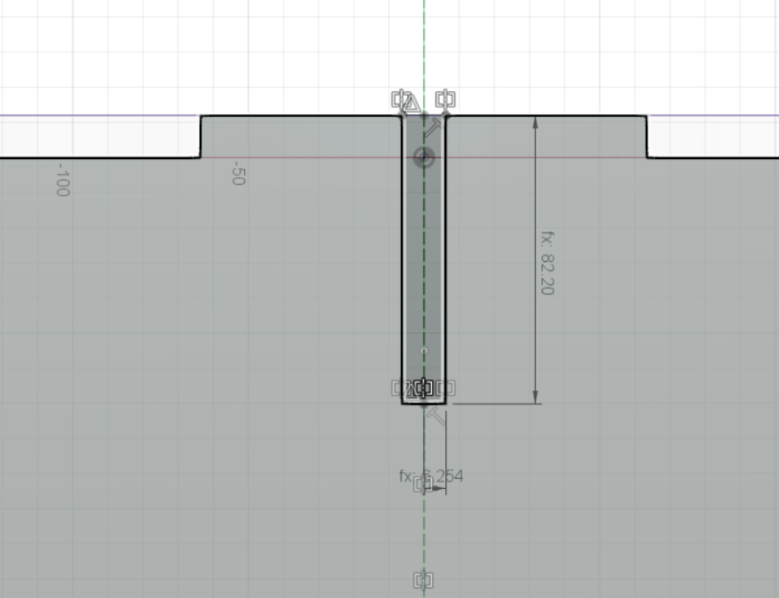
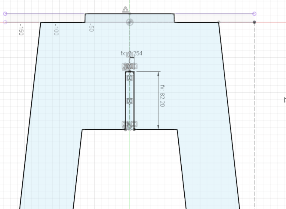
We can repeat the same steps to create joints for the legs. we create one thats half the length from the top half.
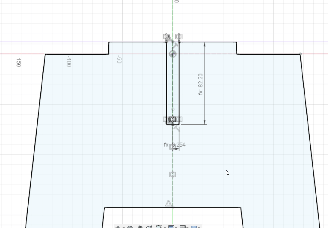
Extrude it by the negative value the width of the leg.
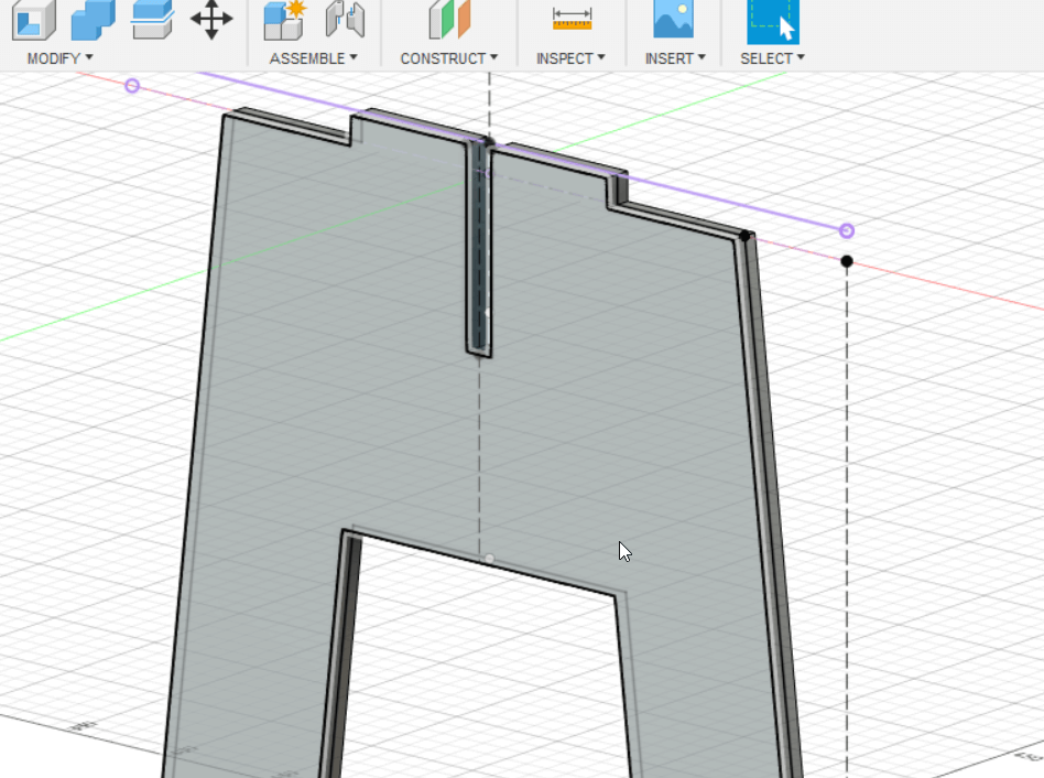
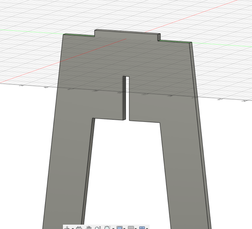
The leg should look like this.
We can repeat the same step for the other leg but this time its half the length from the buttom.
The other leg should look something like this.
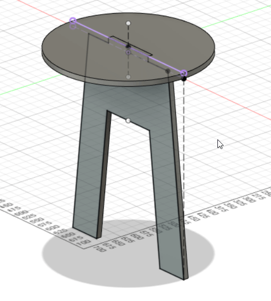
This how the parts look like rendered in fusion 360.
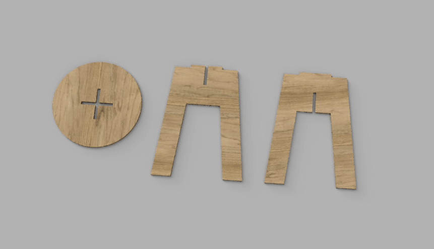
This is a 3D model of the result.
You can download the Dxf files from here
Toolpath
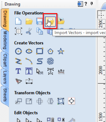
To create the toolpath for the CNC machine I downloaded the the VCarve software from its offical site.
I imported my dxf files using the import vectors button
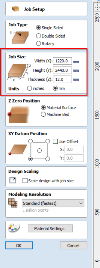
The size of the plywood im going to is is 1220mm x 2440mm with 12mm thickness. I set those dimentions in Vcarve using the Job setup menu.
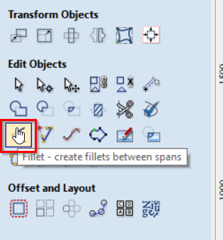
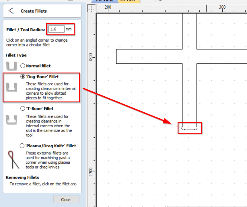
The CNC machine has a difficult time cutting 90 degree corners, a good technique of solving this issue is to create spaces for the machine to move in around corners. This technique is called a Dog-Bone Fillet. This can be accessed in Vcarve using the Fillet tool and then selecting the Dog-Bone Fillet.
I set Fillet radius to 1.6mm and added them to all 90 degree corners.
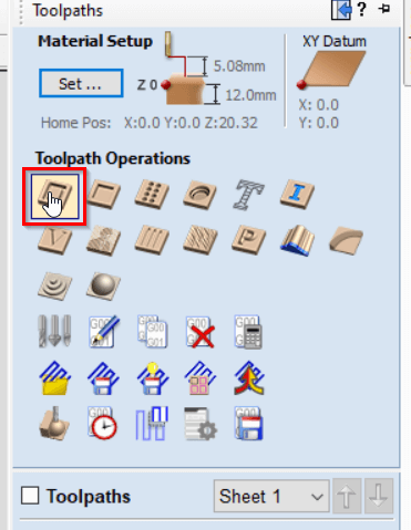
There are many types of toolpath profiles available on Vcarve. In this project I will use the 2D toolpath profile which is the most commonly used profile.
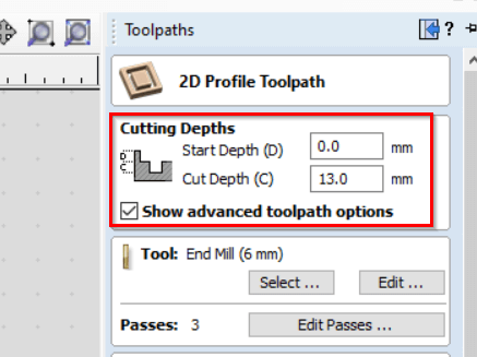
In the 2D profile settings I set the starting depth to 0mm and the cutt depth to 13mm. It is good practice to set the cut depth 1mm more than the material thickness (In this case its 12mm) to ensure that the parts are properly cut.
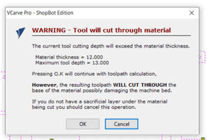
Vcarve warns us that the cutting depth is more than the material thickness but it can be ignored because thats what we want. Keep in mind that the material has a sacrifical layer of wood under it protecting the machine that allows us to exceed the material thickness.
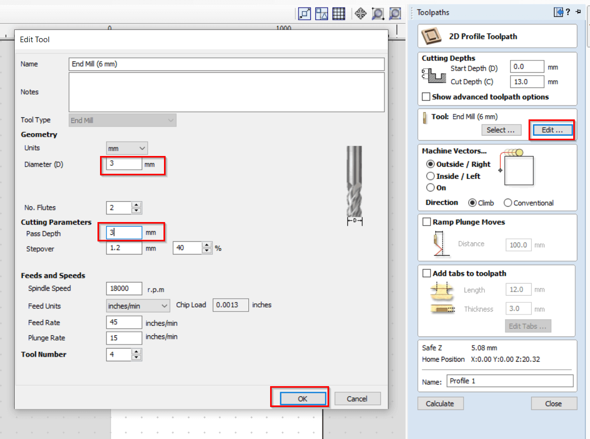
The CNC machine can use different types of drillbits and needs to know what type of drillbit you’ll use. To edit the drillbit used on Vcarve click edit then add the drillbit that you will use.
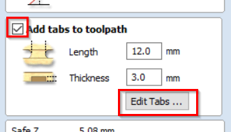
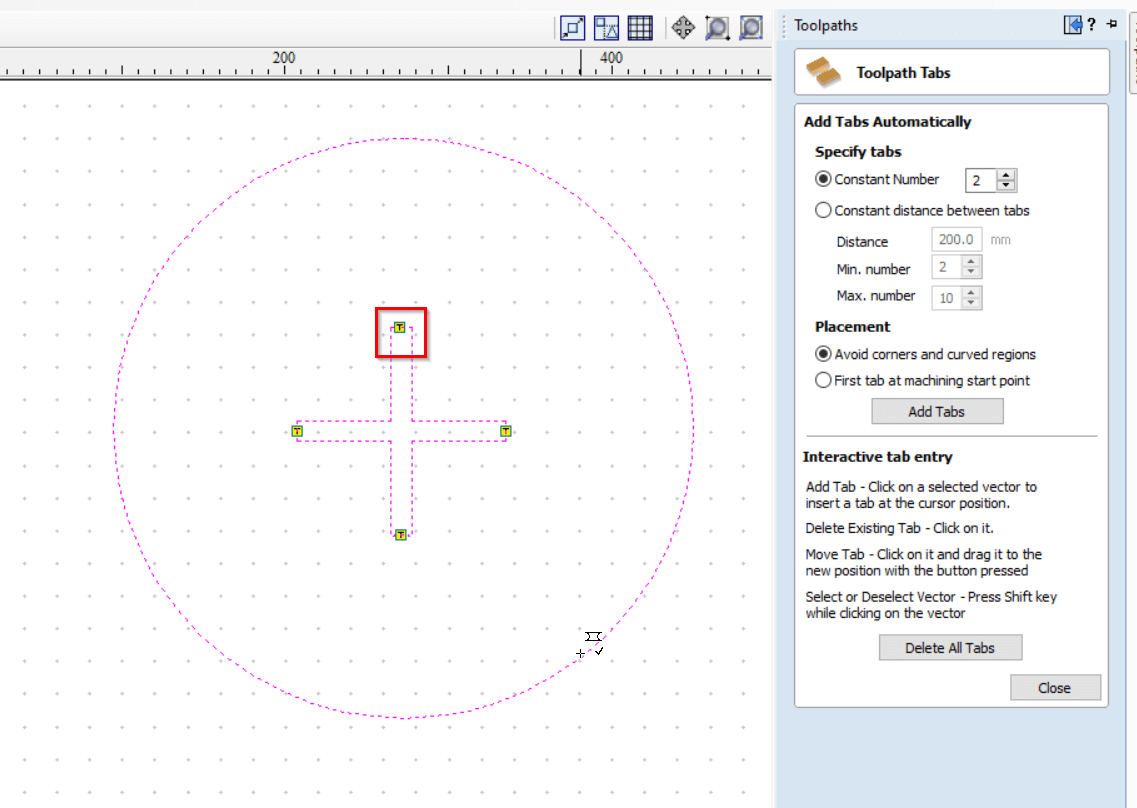
To prevent parts from moving around while the CNC machine is working we need to add tabs. When the CNC machince cuts a part it will leave a thin line holding the part that can be easily be broken off during assembly. These thin lines are called tabs.
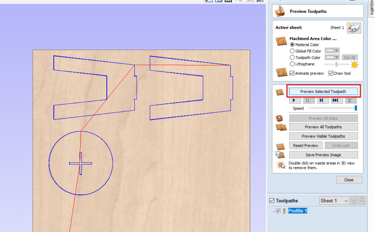
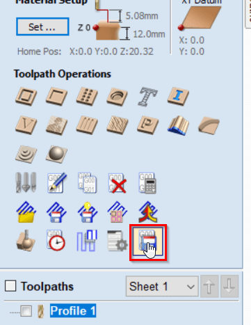
We can preview the toolpath and simulate the cutting process from this menu.
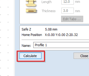
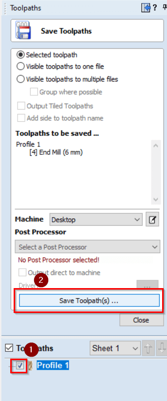
After you are satisfied with the result you can save the toolpath from here.
Cutting
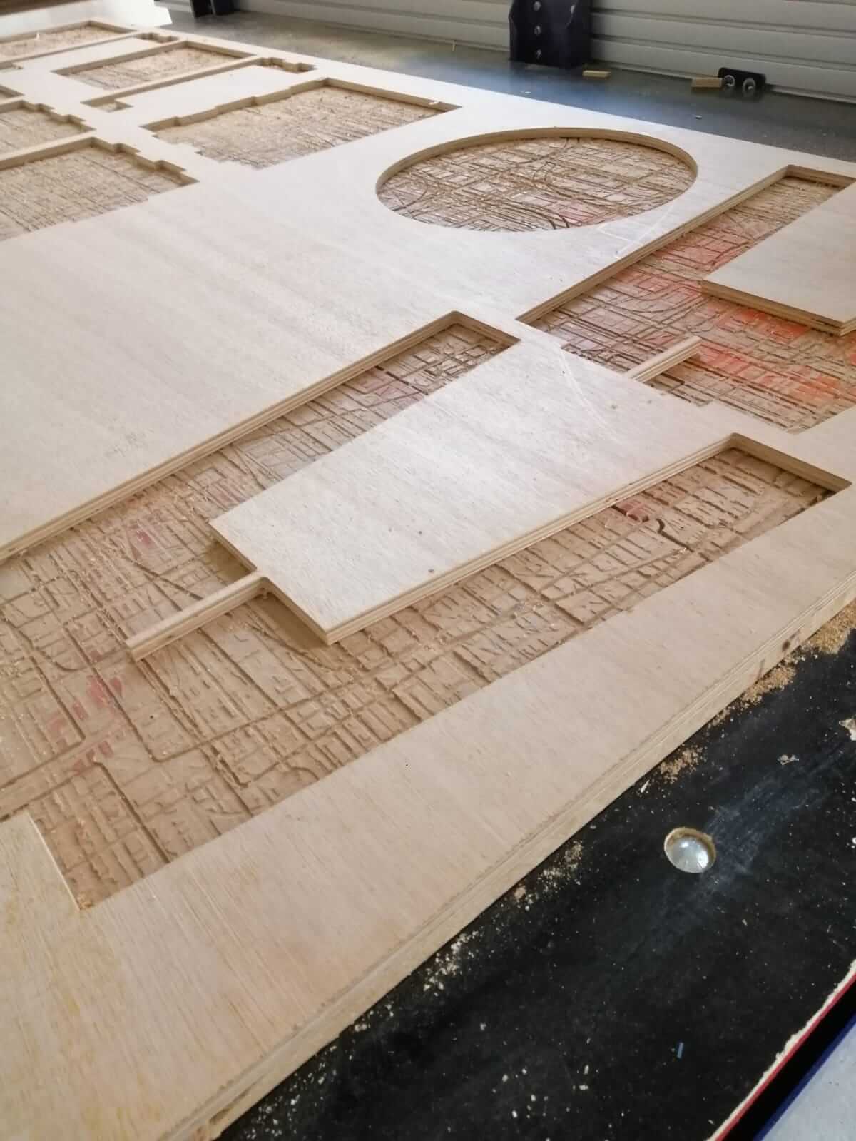
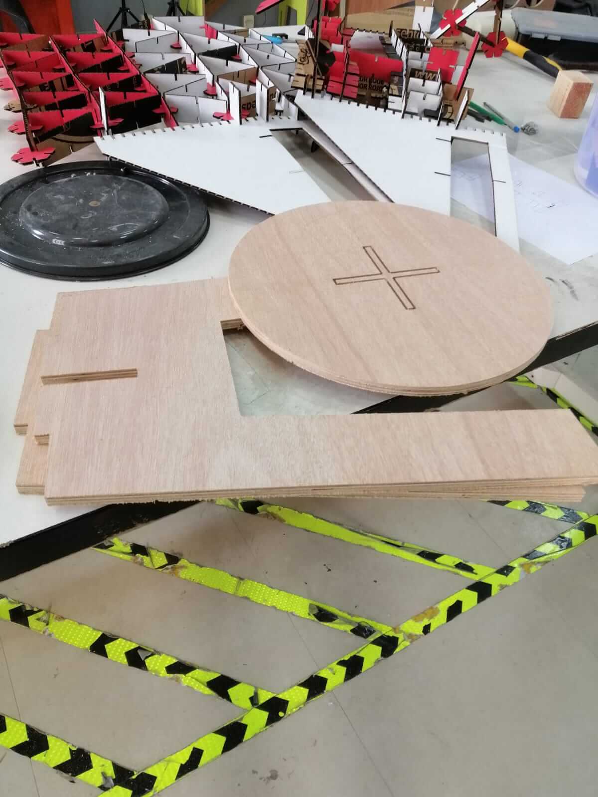
Using the toolpath created I was able to successfully cut the parts without any issues.
You can download the CNC files from here
Assembly
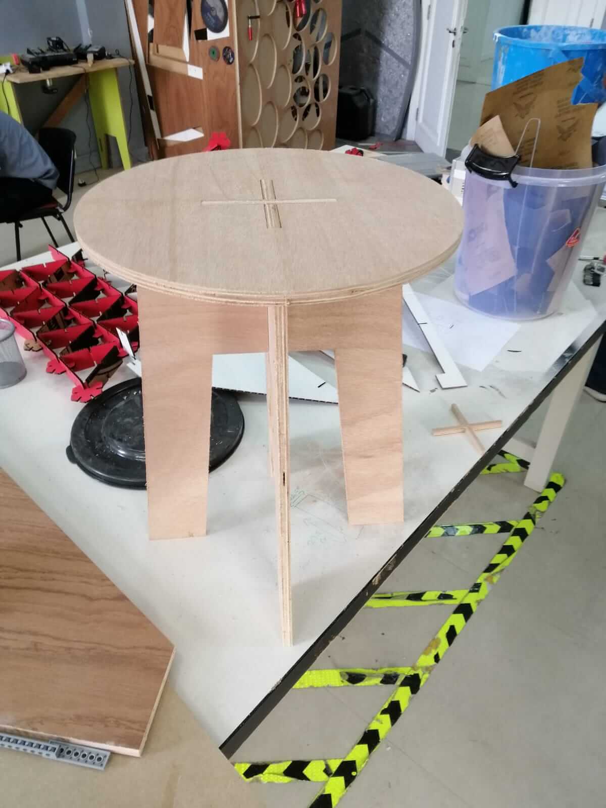
Since the stool consists of only 3 parts it was easy to assemble.
I didn’t like that the edges of the stool were flat.
To round the edges of the stool I deassembled it and used this machine to cutt the edges of every part.
To finish things off I sanded the edges off using sanding paper to make them smooth.
This is the end product.
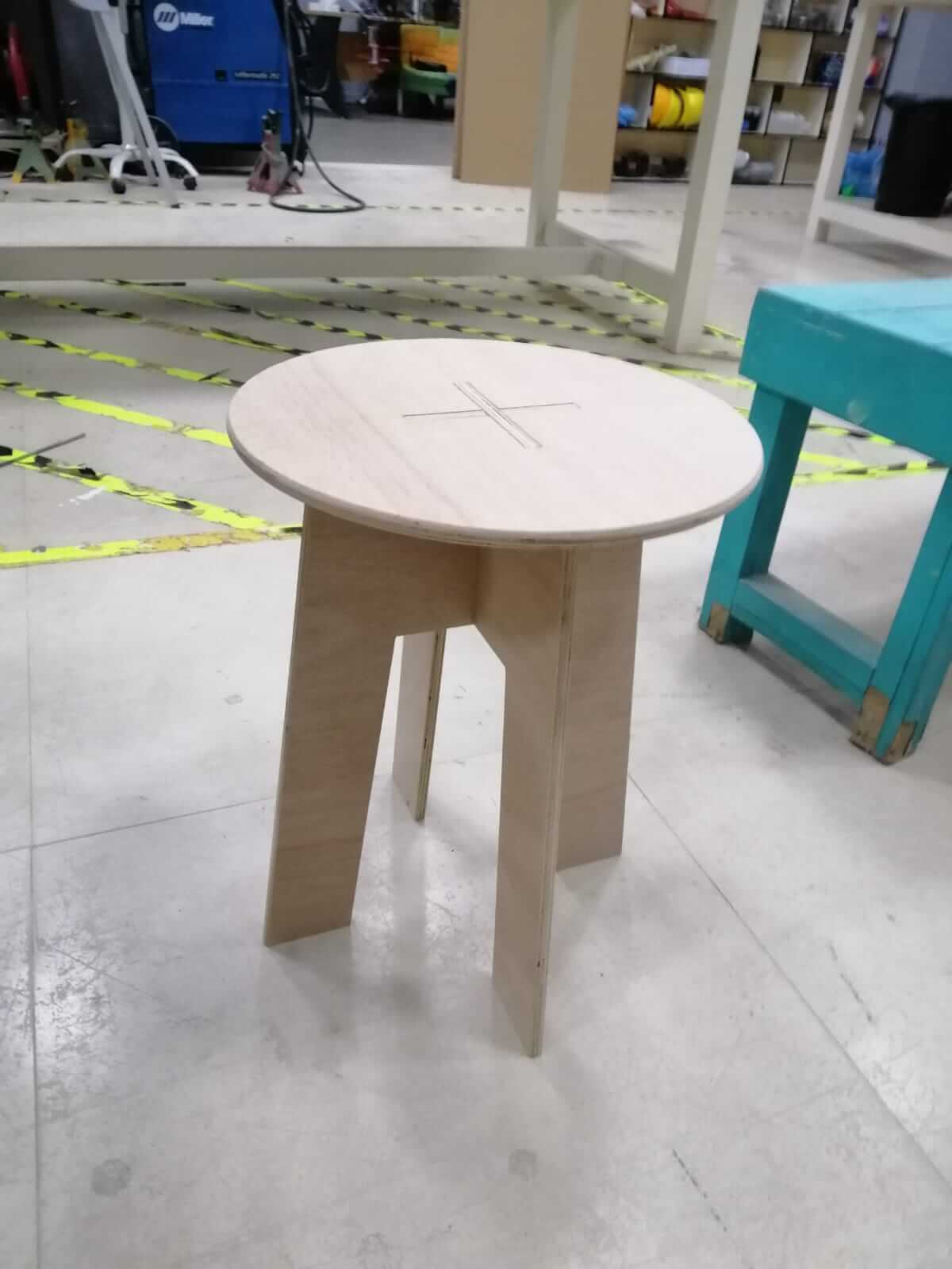
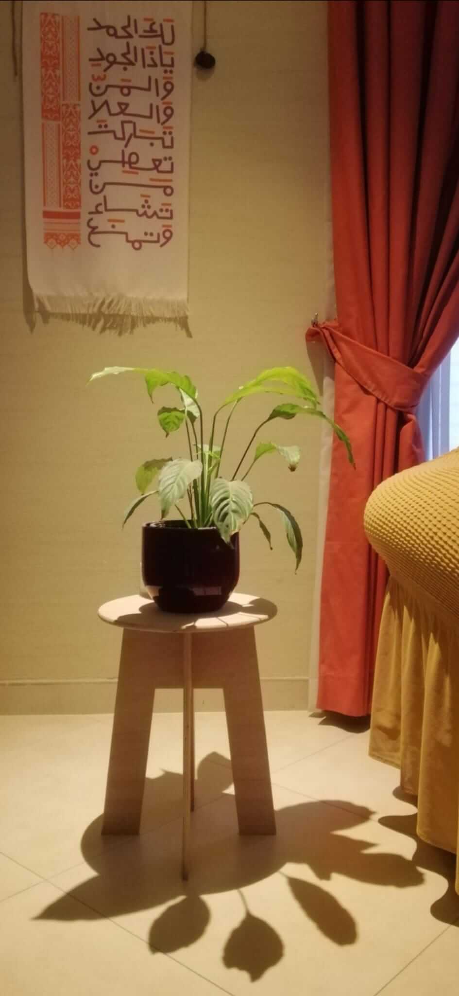
This is how it looks like in our living room :)