4. Embedded programming
This week I worked on Embedded programming.
Group Assignment
Research Microntrollers
Our group did this section, we wrote everything down in this Word Document
Research Programming Languages
Can be found in Zainab Abbas’s website.
Individual Assignment
Setup
Download the Arduino IDE software from this link here.
Follow the instructions on this website to setup development environment.
Programming Micorcontroller (Blink Example)
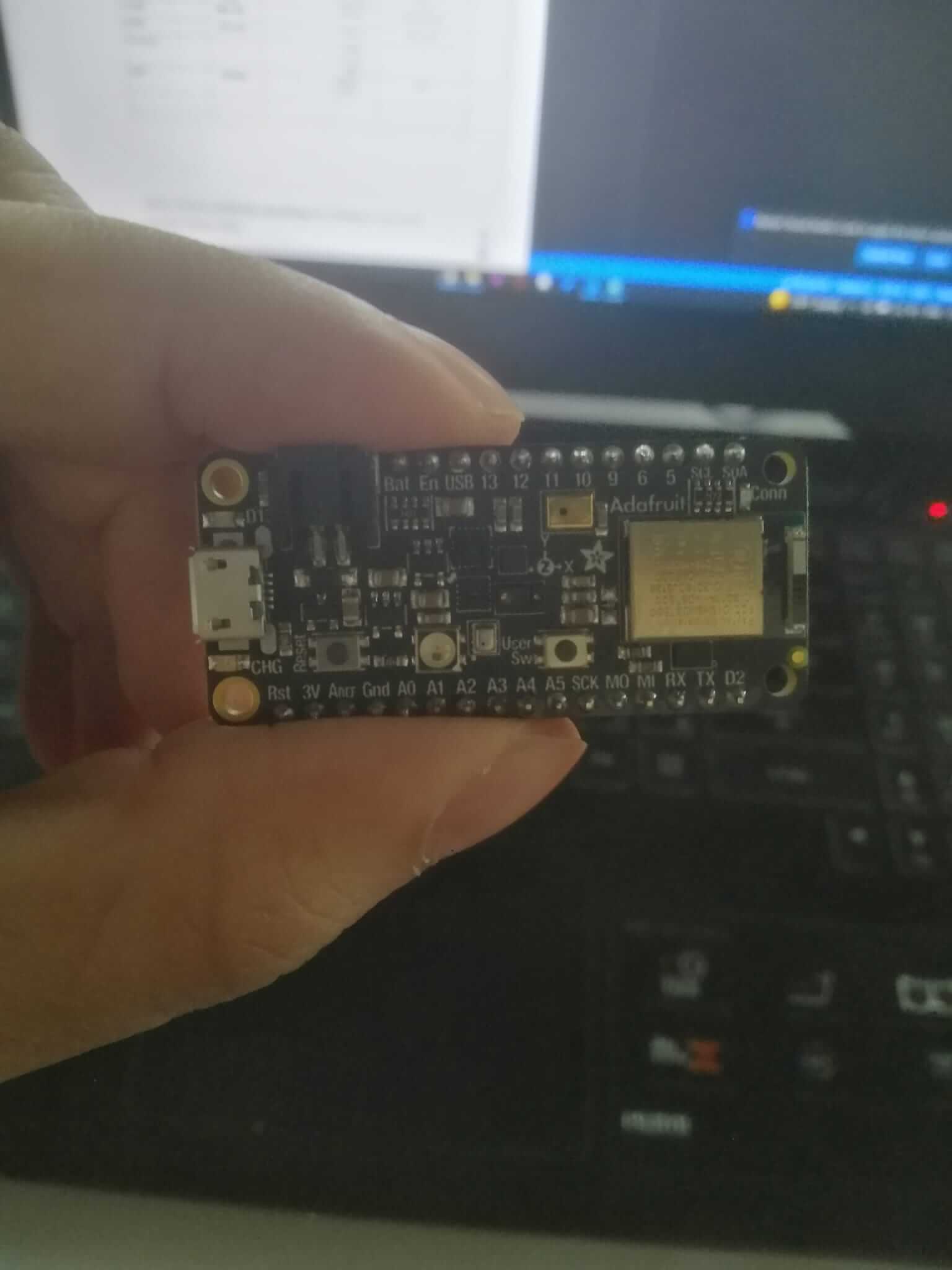
I connected the arduino to my laptop using a usb cable.
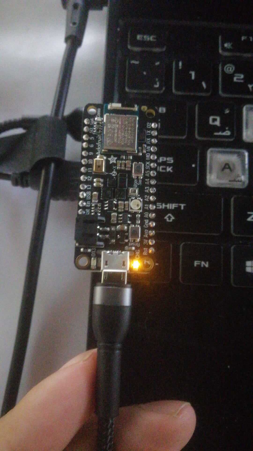 I turned on the device.
Setting up Board and Port
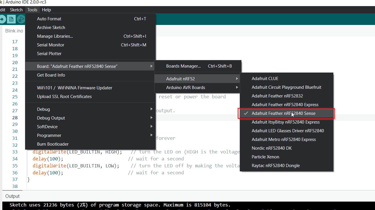
Before doing anything we need to make sure that the software we are using is calibrated to match the arduino model.
In this scenario I am using a Adafruit Feather nRF52840 Sense. more information about the chip can be found on the Adafruit website
To setup the board go to Tools > Board > Adafruit > Adafruit Feather nRF52840 Sense
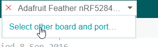
 You can change the port also from the Tools menu, but in my case i am using a new version of Arduino IDE (ver 2.0.0) so the steps are a bit different.
I clicked the board name on the green toolbar and clicked on Select other board and port
You can change the port also from the Tools menu, but in my case i am using a new version of Arduino IDE (ver 2.0.0) so the steps are a bit different.
I clicked the board name on the green toolbar and clicked on Select other board and port
Tip
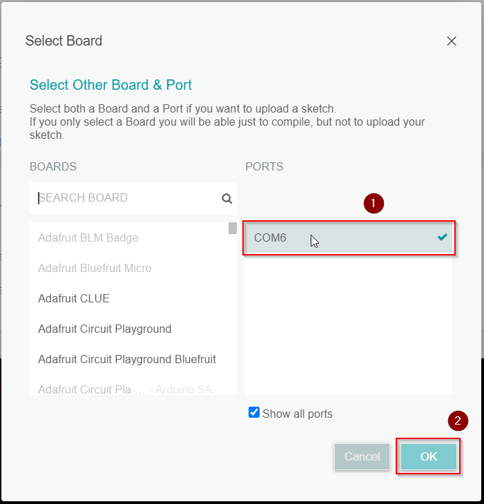
If the Arduino is turned off the ports field will be empty, so make sure its on during this step
Click COM6 then OK
Blink
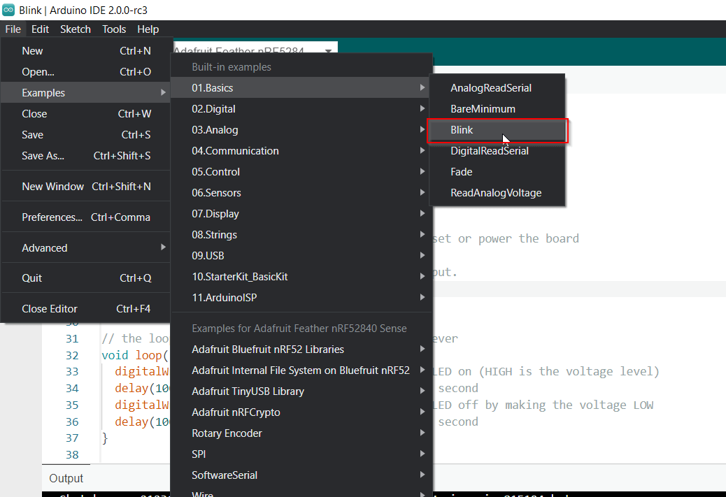
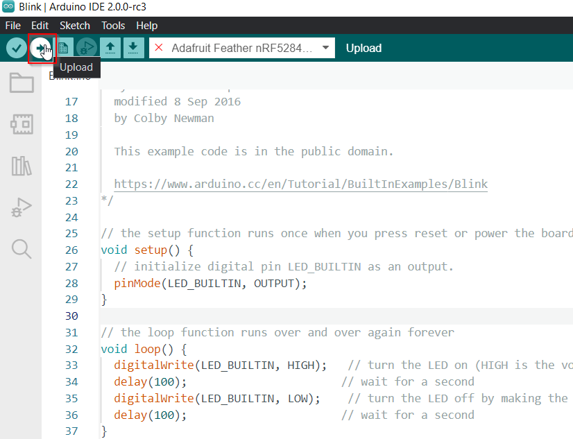
To open the Blink example code go to File > Examples > 01.Basics > Blink
Click upload to run the code.
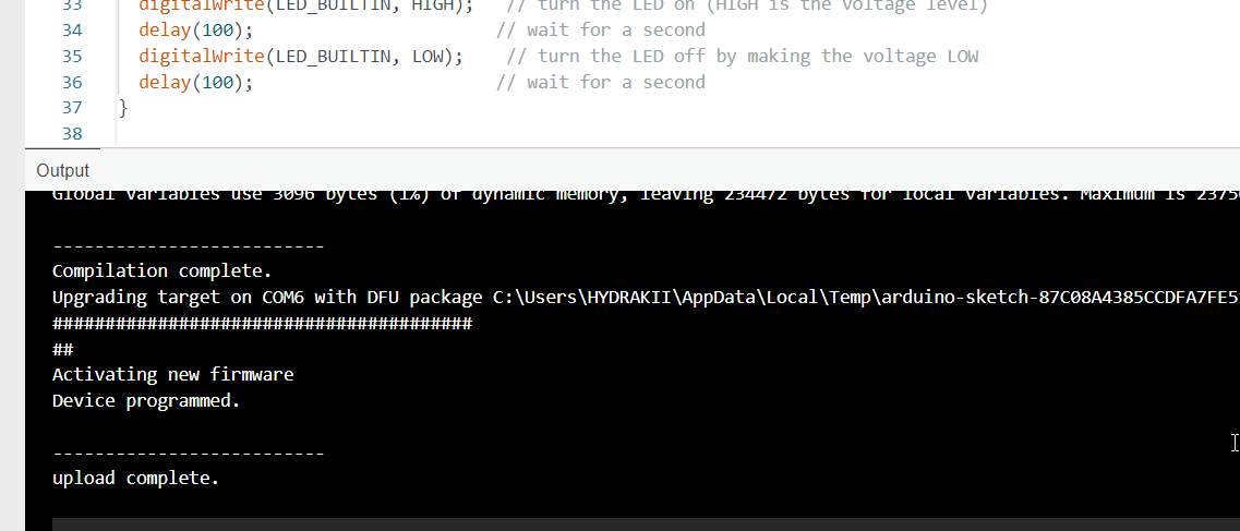
If the uploade was successful you should get this message in your terminal.
Tip
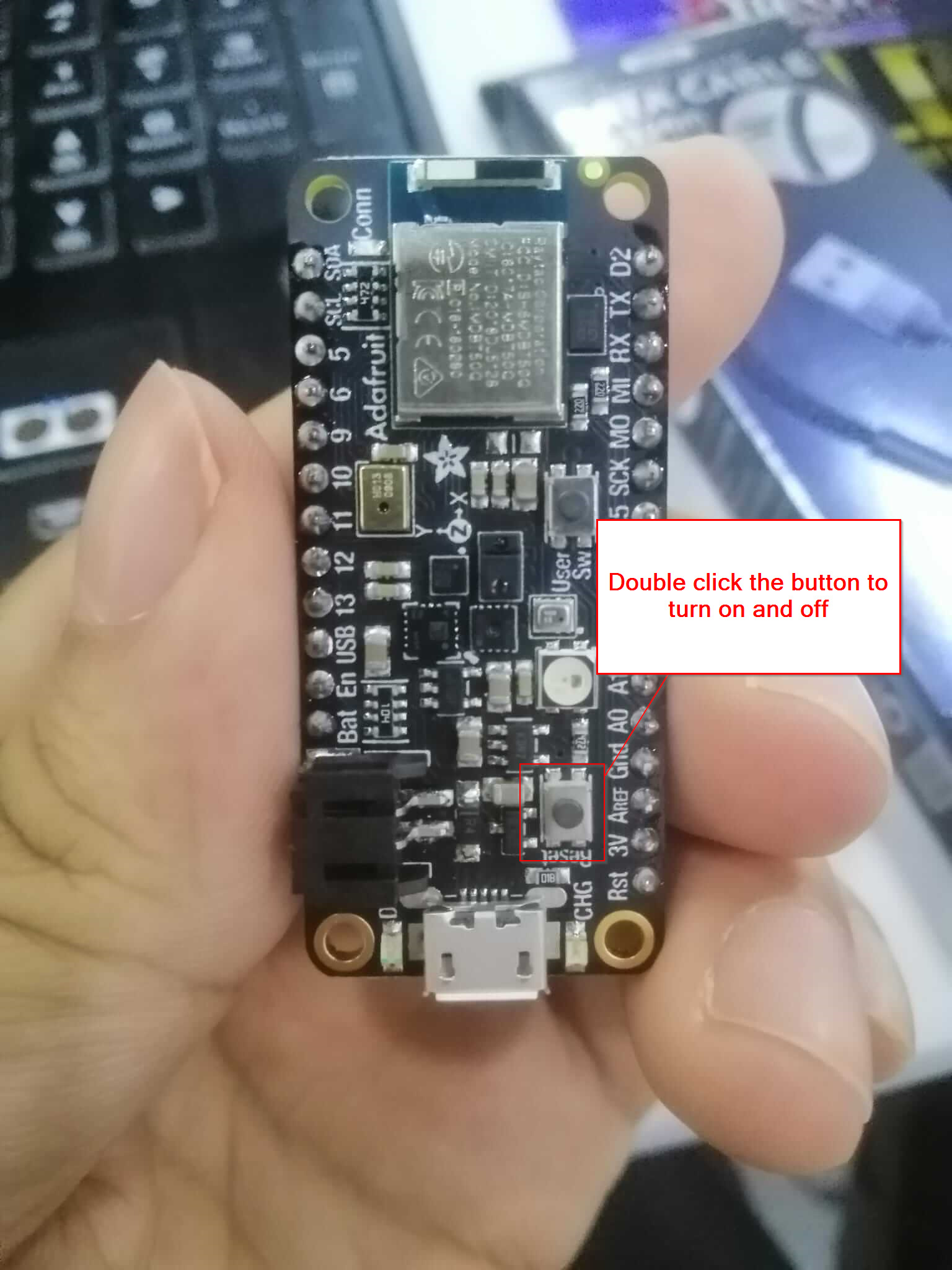
If the code doesn’t work try reseting the Arduino by clicking the power button twice, then try running the code again.
The red light on the Arduino started blinking which means the code is running smoothly.
TinkerCAD
TinkerCAD has a easy way of coding on for the arduino using a simulator.
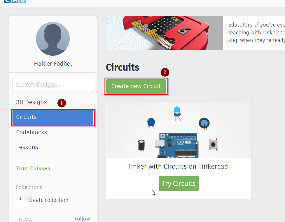
To access this feature go to Circuits then Create new Circuit.
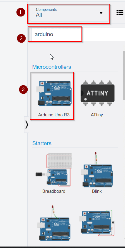
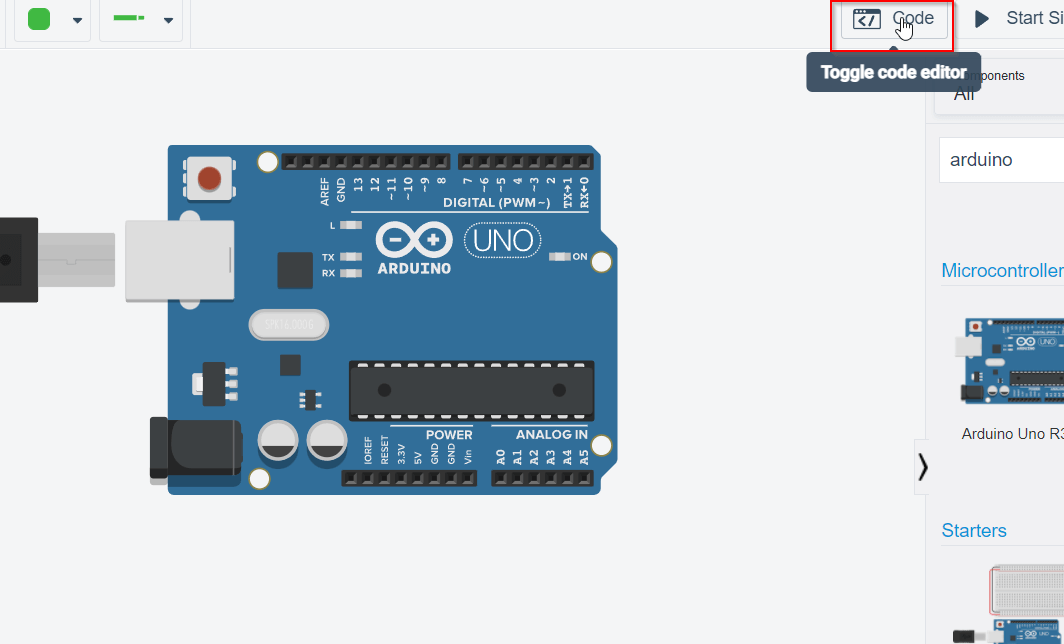
Swicth Components to All, type “Arduino” in the search bar and select Arduino Uno R3.
Select the Code button to display the code editor.
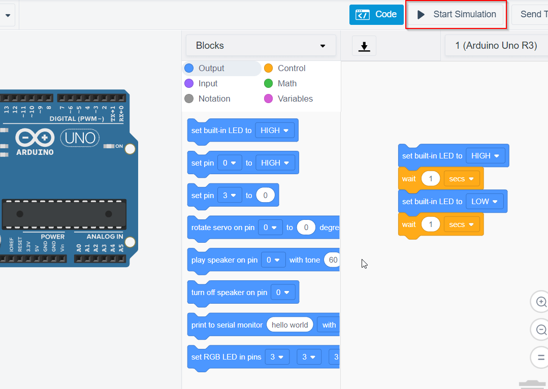
You can run the code using the Start Simulation button.
Challenges
Easy mode
Objective
Blink your led but have your blink delay periods be randomized values between 1 second and 5 seconds
Implementation
I modified the blink code and added the rand() method to generate a random value between 1 and 5 seconds .
 int randOn = 0; // random number for when its on
 int randOff = 0; // random number for when its off
// the setup function runs once when you press reset or power the board
void setup() {
  // initialize digital pin LED_BUILTIN as an output.
  pinMode(LED_BUILTIN, OUTPUT);

}

// the loop function runs over and over again forever
void loop() {
  randOn = random(1000,5000); //generate a time between 1 and 5 seconds
  randOff = random(1000,5000); //generate a time between 1 and 5 seconds
  digitalWrite(LED_BUILTIN, HIGH);   // turn the LED on (HIGH is the voltage level)
  delay(randOn);                       // wait for a second
  digitalWrite(LED_BUILTIN, LOW);    // turn the LED off by making the voltage LOW
  delay(randOff);                       // wait for a second
}
Medium mode 
Objective
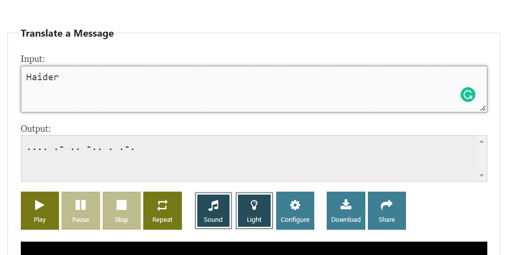
pre code your microcontroller to send a Morse code 1 word message and challenge a friend, family member, your colleagues or your instructor to figure it out. dot = 0.5 second light on. dash=1 second light on. gap between dots and dashes=0.5 second light off. gap between letters=2 second light off
Implementation
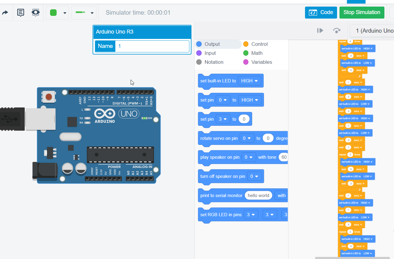
For this challenge I used TinkerCAD blocks to write the code that will display a morsecode message.
First i used a morsecode translator to convert normal text to morse code.
I made the light on the arduino light up at differnent times to create a moerse code.
Heres a table of the different timings i used.
| Morse code | Time of delay |
|---|---|
| . | 0.5 seconds |
| - | 1 seconds |
| space | 1 seconds |
This is the code i developed.
// C++ code
//
int counter;

int counter2;

int counter3;

void setup()
{
  pinMode(LED_BUILTIN, OUTPUT);
}

void loop()
{
  for (counter = 0; counter < 4; ++counter) {
    digitalWrite(LED_BUILTIN, HIGH);
    delay(500); // Wait for 500 millisecond(s)
    digitalWrite(LED_BUILTIN, LOW);
    delay(500); // Wait for 500 millisecond(s)
  }
  delay(1000); // Wait for 1000 millisecond(s)
  digitalWrite(LED_BUILTIN, HIGH);
  delay(500); // Wait for 500 millisecond(s)
  digitalWrite(LED_BUILTIN, LOW);
  delay(500); // Wait for 500 millisecond(s)
  digitalWrite(LED_BUILTIN, HIGH);
  delay(1000); // Wait for 1000 millisecond(s)
  digitalWrite(LED_BUILTIN, LOW);
  delay(500); // Wait for 500 millisecond(s)
  delay(1000); // Wait for 1000 millisecond(s)
  for (counter2 = 0; counter2 < 2; ++counter2) {
    digitalWrite(LED_BUILTIN, HIGH);
    delay(500); // Wait for 500 millisecond(s)
    digitalWrite(LED_BUILTIN, LOW);
    delay(500); // Wait for 500 millisecond(s)
  }
  delay(1000); // Wait for 1000 millisecond(s)
  digitalWrite(LED_BUILTIN, HIGH);
  delay(1000); // Wait for 1000 millisecond(s)
  digitalWrite(LED_BUILTIN, LOW);
  delay(500); // Wait for 500 millisecond(s)
  for (counter3 = 0; counter3 < 2; ++counter3) {
    digitalWrite(LED_BUILTIN, HIGH);
    delay(500); // Wait for 500 millisecond(s)
    digitalWrite(LED_BUILTIN, LOW);
    delay(500); // Wait for 500 millisecond(s)
  }
  delay(1000); // Wait for 1000 millisecond(s)
  digitalWrite(LED_BUILTIN, HIGH);
  delay(500); // Wait for 500 millisecond(s)
  digitalWrite(LED_BUILTIN, LOW);
  delay(500); // Wait for 500 millisecond(s)
  delay(1000); // Wait for 1000 millisecond(s)
  digitalWrite(LED_BUILTIN, HIGH);
  delay(1000); // Wait for 1000 millisecond(s)
  digitalWrite(LED_BUILTIN, LOW);
  delay(500); // Wait for 500 millisecond(s)
  digitalWrite(LED_BUILTIN, HIGH);
  delay(1000); // Wait for 1000 millisecond(s)
  digitalWrite(LED_BUILTIN, LOW);
  delay(500); // Wait for 500 millisecond(s)
  delay(1000); // Wait for 1000 millisecond(s)
Microcontroller Datasheet
#### Introduction
More information can be found in the Datasheet.
#### Sensors
There are several different sensors built in the arduino.
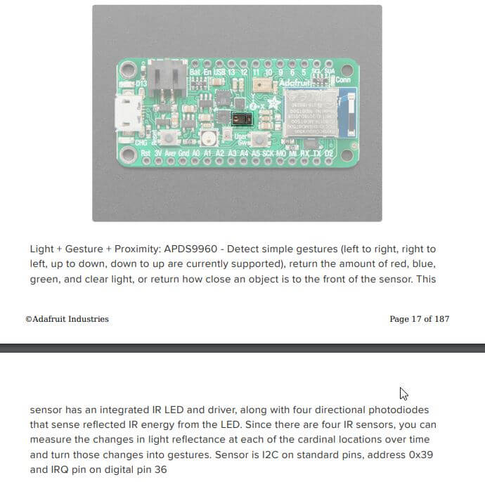
##### Proximity, Light, Color, and Gesture Sensor
This sensor can detect gestures, return different colored lights and even detect how far an object is from it.
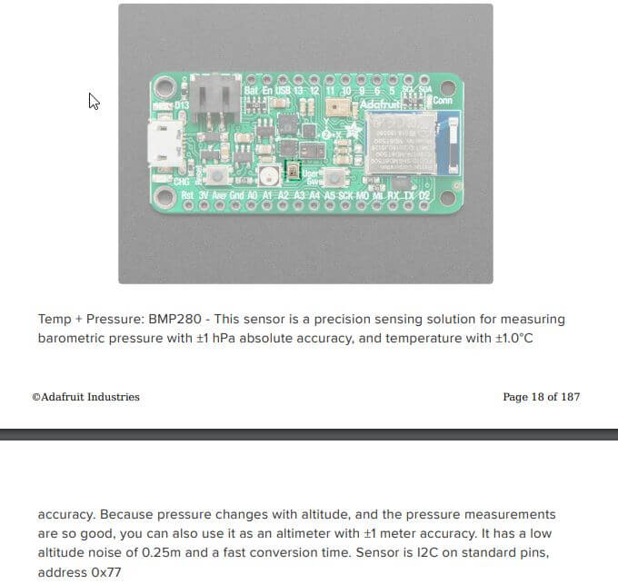
##### Temperature and Barometric Pressure/Altitude
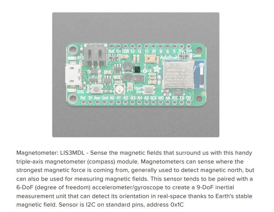
##### Magnetometer Sensor
This sensor can detect magnetic forces.
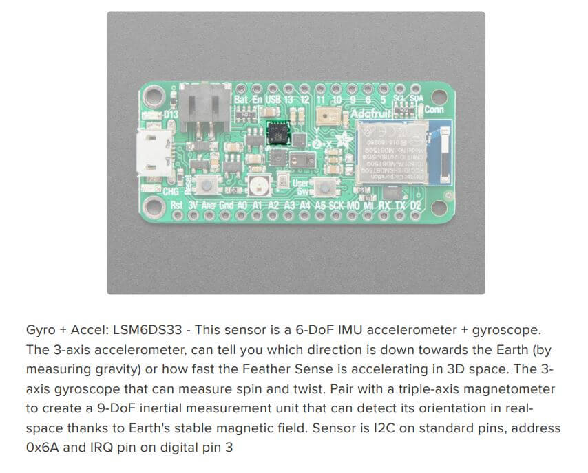
##### Accel/Gyro Sensor
I gyro sensor detects 3D movement of the arduino.
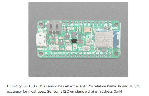
##### Humidity Sensor
The arduino can also detect the humidity.
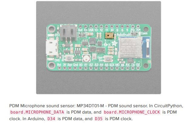
##### Microphone Sensor
The arduino can collect sound using a sound sensor.
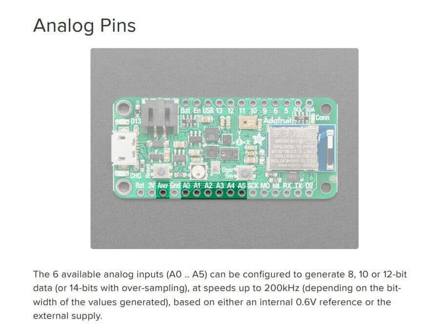
#### Digital Pins & Analog Pins
The main difference between digital pins and analog pins is that digital pins take a value of either of 0 and 1. Analog pins can do the same as digital pins and can also take a range of values from 0 to 1023.
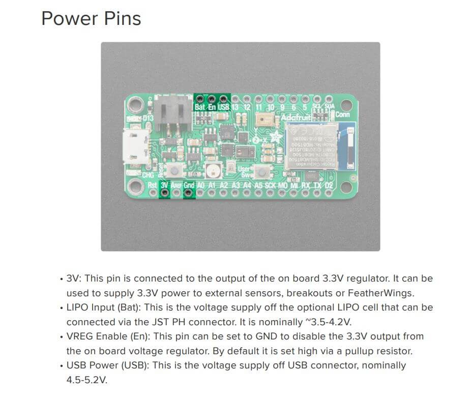
#### Power Pins
There are output pins that support usb power.
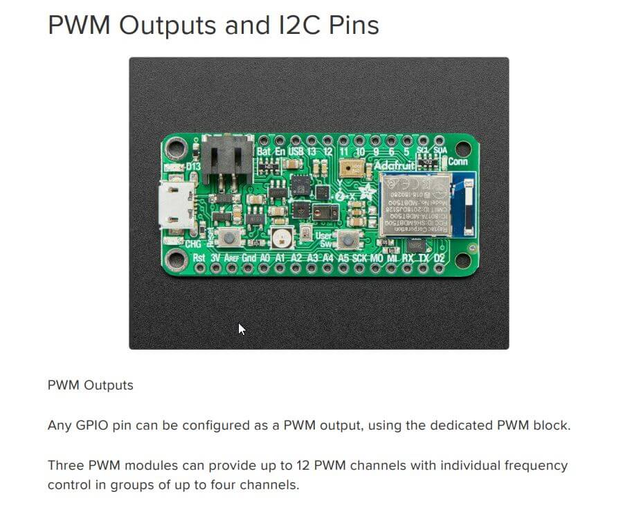
#### Pwm
Pulse Width Modulation, or PWM, is a technique for getting analog results with digital means.